STAS BuildStar Alu User manual

STAS - Instructions for use moving floor
1
Moving Floor
INSTRUCTIONS FOR USE

EN - MOVING FLOOR - V1

STAS - Instructions for use moving floor
3
TABLE OF CONTENTS
A. INTRODUCTION 4
1. GENERAL 4
2. SAFETY AT WORK 4
3. NOTES 4
B. SAFETY REGULATIONS 4
1. PREVENTION OF ACCIDENTS AND OVERVIEW OF
WARNINGS AND SAFETY MEASURES 4
1.1. General 4
2. PERSONAL PROTECTIVE MEASURES 4
2.1. Footwear 4
2.2. Clothing 4
2.3. Goggles 4
2.4. Gloves 4
2.5. Ear protection 4
3. PICTOGRAMS 5
C. GENERAL DESCRIPTION MOVING FLOOR 6
1. TRAILER 6
2. MOVING FLOOR SYSTEM 6
2.1. Principle of operation 7
2.2. Speed and maximum load 8
3. INTENDED USE MOVING FLOOR SYSTEM 8
4. TRAILER IDENTIFICATION 8
4.1. Position of identification plate and trailer identification number 8
4.2. Identification plate 8
4.3. Trailer identification number 9
D. SYSTEM DESCRIPTIONS 9
1. KINGPIN, FIFTH WHEEL RUBBING PLATE AND FIFTH WHEEL 9
2. LANDING LEGS 9
2.1. Description 9
2.2. Operation steel type landing leg 10
2.3. Operation aluminium type landing leg 10
3. BRAKES 11
3.1. General 11
3.2. EBS 11
3.3. Brake connection 15
3.4. Prevention of premature brake wear 16
3.5. Brake synchronisation 16
3.6. Brake plate 16
3.7. Drum brake 16
3.8. Disc brake 16
3.9. Parking brake – spring brake cylinders 17
3.10. Emergency brake 17
4. AIR SUSPENSION 18
4.1. General 18
4.2. Raising and lowering valve 18
4.3. SmartBoard 19
4.4. Load indication through SmartBoard and any possibly calibration 20
5. WHEEL ACCESSORIES 20
5.1. Tyres and rims 20
5.2. Spare wheel and spare wheel carrier 20
5.3. Wheel chock 21
5.4. Mud guards and mud flaps 21
6. DOORS 21
6.1. Barn doors 21
6.2. Hydraulically operated top swinging door 22
6.3. Inspection door 23
7. ROOF COVERING 23
7.1. Catwalk with ladders 23
7.2. Roof sheet 24
7.3. Hydraulically operated roof nets 24
7.4. Opening the hydraulically operated roof nets 25
7.5. Closing the hydraulically operated roof nets 25
8. MOVING FLOOR SYSTEM ACCESSORIES 25
8.1. Moving bulkhead with floor sheet 25
8.2. Detachable funnel 26
9. LIGHTING AND SIGNALISATION 27
10. VARIOUS ACCESSORIES 28
10.1. Tool box 28
10.2. retractable ladder for accessing load space 28
10.3. Side guards 28
10.4. Ladder 29
11. OPTIONS 29
11.1. Alloy rims 29
11.2. Rear light protection 29
11.3. Additional rear door lock 29
E. SPECIFIC PROCEDURES 30
1. TRAILER COUPLING AND UNCOUPLING 30
1.1. COUPLING 30
1.2. Uncoupling 30
2. TRAILER LOADING AND UNLOADING 30
2.1. Safety instructions 30
2.2. Loading the trailer 31
2.3. Unloading the trailer 32
2.4. Emergency control unit 33
F. PREVENTIVE MAINTENANCE 34
1. MECHANICAL MAINTENANCE 34
1.1. Visual inspection 34
1.2. Tyres 34
1.3. Tightening torques for bolts 34
2. MAINTENANCE SCHEDULE TRAILER BODYWORK 35
3. MAINTENANCE SCHEDULE MOVING FLOOR SYSTEM 35
4. WHEELS 35
G. TROUBLESHOOTING MOVING FLOOR SYSTEM 36
1. MOST COMMON PROBLEM CAUSES 36
2. CARGO FLOOR®SYSTEM 37
3. WABCO DIAGNOSES 37
3.1. Via Interface and PC with voltage supply ISO7638 37
3.2. Through SmartBoard 37
H. TECHNICAL SPECIFICATIONS 39
1. TRAILER - MECHANICAL 39
1.1. Kingpin and fifth wheel rubbing plate 39
1.2. Aluminium landing legs 39
1.3. Steel landing legs 39

STAS - Instructions for use moving floor
4
A. INTRODUCTION
1. GENERAL
2. SAFETY AT WORK
3. NOTES
We would like to congratulate you on the purchase of your new STAS nv trailer.
STAS trailers have been built to serve the user for many years. If the trailer is used and maintained in accordance with
the legal provisions and professional regulations, we can guarantee you many years of reliable operation.
We recommend you study the instructions and accompanying documentation carefully prior to using the trailer in
order to familiarise yourself with all functions of the trailer and to enable you to use it in the best possible manner.
Your trailer has been designed in accordance with current safety standards.
We wish you every enjoyment in the use of your new trailer.
The STAS-team.
An up-to-date list of STAS sales points and recognised service points can be found on our website:
www.stas.be or www.alutrailer.com.
This manual and accompanying documentation have been drawn up with the following in mind: prevention is better
than cure. We would therefore ask you to take note of the following.
Although every care has been taken during the compilation and verification of this manual, it may be possible that, as
a result of technical progress, certain components vary slightly from the illustrations in the text. STAS nv reserves the
right to apply modifications without prior notice and cannot be held liable for any possible errors.
These instructions apply to trailers with a number of different options. It is possible certain options have not been
fitted to your trailer, or are not available for your type of trailer.
This manual should always be kept with the trailer and the operator must be able to refer to it at any time.
This manual was originally published in Dutch and you may have a translated copy of the original. The original Dutch
manual is also available on request.
The following information is important and should be taken into account when referring
to the manual:
• The “front” is the side of the trailer closest to the tractor.
• The “rear” is the side of the trailer furthest from the tractor.
• In order to determine the left and right hand side, the operator should be looking
from the rear to the front of the trailer.
The pictures in this manual are not taken on 'UK trailers' (trailers driven on the left) but
on 'continental trailers' (trailers driven on the right). This implies that certain compo-
nents will be on the other side of the trailer than shown in the pictures. E.g. position of
spare wheel carrier, tool box, control units ...
You will have been made aware of the main operational and safety instructions for your
trailer at the time of delivery. Please apply them correctly.
Please study these instructions and accompanying documentation carefully prior to
including the trailer in your trailer fleet.
Please ensure the driver of this trailer is also familiar with these instructions.
1. PREVENTION OF ACCIDENTS AND OVERVIEW OF WARNINGS AND SAFETY MEASURES
2. PERSONAL PROTECTIVE MEASURES
1.1. GENERAL
2.1. FOOTWEAR
2.2. CLOTHING
2.3. GOGGLES
2.4. GLOVES
2.5. EAR PROTECTION
As STAS nv is not aware of the conditions in which the trailer will be used, the company cannot assess the risks caused by
external factors. In the interest of his employees and any other third parties which may be involved, the owner of the trailer
should arrange for a risk analysis relating to these external risks to be carried out. The owner of the trailer can then use
this risk analysis to arrange training for any personnel who may be using the trailer.
It is strongly recommended that operators who are new to the trailer and the moving floor system learn to use it with the
trailer in an unloaded condition.
Any possible information regarding regulations relating to unloading yards, safety procedures, etc. required by drivers who
are not employed by the company where the unloading is taking place should always be obtained.
Always inform the person in charge of your arrival and your departure and comply with the driving and unloading procedu-
res in the unloading yard and the general instructions on site.
Never reverse your trailer without first ensuring it is safe to do so. Ensure there is no one in the danger zone around the
trailer. If there is a signalling person present in the unloading yard, ensure that both parties are familiar with the signals
being used. Cease any movement if you can no longer see the signalling person.
When operating the moving floor trailer, protective footwear should be worn at all times. Footwear may include fixed, high
fitting shoes with steel toe caps and insulating soles. Slippers, loose fitting shoes, or shoes which could endanger the
operator or which do not offer sufficient protection should never been worn.
Suitable clothing should ensure the operator is visible while carrying out his work and this will contribute to the general
safety. Clothing should never be left loose and must always be done up. It should preferably be of an eye-catching colour
and be fluorescent which will also offer additional visual safety.
Tijdens het lossen en/of laden van de oplegger kunnen deeltjes van de lading rondvliegen. Daarom moet de bediener van
de oplegger steeds een goedgekeurde veiligheidsbril dragen, vanaf het moment dat hij de trekker verlaat tot wanneer hij
terugkeert in zijn cabine.
The operator of the trailer should always wear safety gloves in order to avoid injuries caused by sharp or protruding com-
ponents. Gloves may also offer protection against injuries caused by the nature and characteristics of the load.
It is recommended that the operator of the trailer wears ear protection while operating the moving floor system.
This manual contains some pictures on which the operator does not wear safety gloves.
These pictures were taken deliberately that way, only for the clearness of the picture
itself.
B. SAFETY REGULATIONS

STAS - Instructions for use moving floor
5
Some of the pictograms listed below can be found on the trailer and/or on the following pages of this user manu-
al. The following is an overview of the warnings and safety measures applicable to your trailer.
This pictogram appears in various places in this manual and indicates measures which
should be observed in order to guarantee safety.
This manual should therefore be studied carefully prior to attempting to use the trailer. If
particular chapters or paragraphs are unclear, please do not hesitate to contact STAS nv! You
should also ensure that everyone who is authorised by you to use the trailer, is familiar with
and understands these instructions.
The moving floor system is a machine as described in the machinery directive. The trailers
are therefore designed to ensure that they comply with the fundamental health and safety
requirements as laid down in the 2006/42/EEC machinery directive.
The moving floor system may only be used when the trailer is coupled to the tractor.
This CE marking confirms the conformity with the machinery directive.
This pictogram indicates areas which could present a hazard for fingers and/or other parts of
the body. The hazardous areas themselves are indicated by hatched lines.
This pictogram indicates areas where fingers and/or other parts of the body are at risk of
being cut. The hazardous areas themselves are indicated by hatched lines.
This pictogram indicates the boundary of an area which is not accessible during normal
operation.
This pictogram indicates the outer most moving part of the trailer and is also used to indicate
the hazardous areas where trapping of hands and/or other parts of the body could occur.
This pictogram indicates the presence of electrical voltage. The trailer receives 24V DC from
the towing vehicle.
Damaged electrical conductors should be replaced or repaired immediately as they could
cause short-circuiting, physical injuries or fire.
The components of the electrical system have been carefully balanced. The electrical system
for your trailer therefore conforms to the EMC directive.
This pictogram can be found near electrical connections. It serves to remind the operator
that it is not allowed to disconnect the electrical connections by pulling the cable.
This pictogram can be found near the trailer doors. It serves to remind the operator to ensure
there is no one in the immediate vicinity when the doors are opened or closed. In this way,
any trapping hazards can be avoided.
This pictogram indicates that wearing gloves is strongly recommended.
3. PICTOGRAMS
B. SAFETY REGULATIONS
This pictogram indicates that wearing safety goggles is strongly recommended.
This pictogram indicates that wearing safety boots is strongly recommended.
This pictogram indicates that wearing a safety helmet is strongly recommended.
This pictogram indicates that the person on the catwalk should protect himself by wearing a
safety harness.
This pictogram indicates the danger of falling objects when opening the roof nets or roof
sheet.
This pictogram indicates the date on which the trailer was painted. This date is important
as the trailer should not be cleaned with a high-pressure hose until 4 weeks after it was first
painted.
During cleaning:
• the maximum water temperature should be no more than 65°C,
• only neutral cleaning substances should be used.
This pictogram indicates a slippery surface as a result of spilt oil.
The moving floor system, as well as the hydraulically operated top swinging door and the roof
net (if fitted to the trailer) are hydraulically operated by means of oil pressure. When coupling
or uncoupling these systems, oil may be spilt. Spilt oil should be removed immediately as it is
harmful to the environment and can cause a slipping hazard.
The stability of the trailer, during driving as well as unloading, is determined to a large degree
by the way in which the trailer is loaded. Ensure the load is evenly distributed at all times.
As manufacturers of trailers, we would like to improve lorry safety through optimum distributi-
on of the brake force between the tractor and the trailer.
We therefore recommend a BRAKE SYNCHRONISATION is carried out between the first 2000
and 10000 km each time the tractor is changed in order to achieve the best possible brake
force distribution and pattern of wear. Please contact the truck manufacturer for a brake
synchronisation.

STAS - Instructions for use moving floor
6
C. GENERAL DESCRIPTION MOVING FLOOR
The trailer is mounted on 9 ton or 10 ton axles in a low maintenance concept. All axles
are fitted with a brake in accordance with the 71/320/EEC and UN/ECE-R13 regulati-
on. The choice of brand for the axles depends on the country or the client. The axles
should always be fitted with universal wheel bolts, universal wheel nuts and wheel hub
centring.
The air suspension will be of the same manufacture/make as the axles.
1. TRAILER
The main components of the trailer are:
• the alloy subframe with a number of crossbars onto which the air suspension, axles, valves,… have
been mounted,
• the side walls and front section consisting of alloy plank rails,
• the doors and roof covering,
• the axles with associated braking system,
• the air suspension with air bags,
• the landing legs and wheel accessories,
• the lighting and signalization,
• the reinforced construction at the front for mounting the fifth wheel rubbing plate together with the
kingpin, as well as the lead on plate, to the cross members.
2. MOVING FLOOR SYSTEM
The moving floor system offers all advantages of an even loading floor, combined with a multitude of materials which can
be automatically unloaded.
The two possible versions with analogue operation are:
• the Cargo Floor®system.
The moving floor system may only be used by trained personnel. Improper use can
cause serious damage and/or injuries.
STARS
We offer extensive option packages for every
STAR. Discover the specialised options at
www.stas.be/mystar or from a dealer in
your area.
MOVING FLOOR TRAILERS - TIPPERS
Discouver our
SPECIALISED OPTIONS
www.stas.be/mystar
BUILD RECYCLING AGRO

STAS - Instructions for use moving floor
7
C. GENERAL DESCRIPTION MOVING FLOOR
2.1. PRINCIPLE OF OPERATION
The principle of operation for the moving floor system is based on the friction between the load and the floor. The floor
consists of a number of spaced floor slats. Three double-acting hydraulic cylinders and associated cross members (one for
each cylinder) move these floor slats backwards and forwards.
Each cross member is connected to and therefore also responsible for the movement of 1/3 of the total number of floor
slats.
The unloading cycle consists of four continuously recurring stages, as illustrated in Fig 2.1.a.
Stage I
Cylinder 1 (and the associated floor slats) moves towards the front of the loading floor. As only 1/3 of the floor is moving,
and 2/3 is standing still, the load does not move. This is because the friction of the stationary (larger) floor area is larger
than the friction caused by the moving floor slats. At the end of the stroke, the cylinder activates a check valve which
ensures the oil flow activates cylinder 2 resulting in the start of stage II.
Stage II
Cylinder 2 (and the associated floor slats) moves towards the front of the loading floor, and the load still does not move. At
the end of the stroke, the cylinder activates a second check valve which ensures the oil flow activates cylinder 3 resulting
in the start of stage III.
Stage III
Stage III is identical to stages I and II but this time it applies to the remaining floor slats. Cylinder 3 (and associated floor
slats) moves towards the front of the loading floor. The load does not move. At the end of the stroke, when all cylinders
are positioned next to each other, the cross member connected to the cylinder activates the switching valve. The switching
valve switches the pressure to the front end of all cylinders (1, 2 and 3) and stage IV starts.
Stage IV
All cylinders (and all floor slats) move back towards the rear of the loading floor. The floor subsequently moves the
load over a distance equal to the stroke of the hydraulic cylinders. At the end of the stroke, the switching valve swit-
ches the pressure back to the rear end of all cylinders. The cycle is now complete and stage I follows.
STAS - Instructions for use moving floor
8
C. GENERAL DESCRIPTION MOVING FLOOR
2.2. SPEED AND MAXIMUM LOAD
Loading and unloading times are determined by the speed of the cylinders and their speed is subject to the oil flow to
the cylinders.
The maximum load which the system is able to move, is determined by the force exerted by the cylinders onto the
floor. This force is subject to the oil pressure.
The hydraulic pump determines both the oil flow and the maximum oil pressure and therefore both the loading and
unloading times and the maximum permissible load. In order to protect the system, pressure is limited by a pressure
relief valve.
Loading and unloading times may be speeded up by increasing the oil flow. The oil
pressure does not affect the loading and unloading times.
System pressure is determined by the load resistance, and not by the position of the
pressure relief valve or the pump.
3. INTENDED USE MOVING FLOOR SYSTEM
The application area for the moving floor system (standard system) is mainly located in the transport of:
• Potatoes
• Beet and pulp
• Tree bark
• Bulk products
• Pressed bales
• Cereals
• Blocks of wood
• Wood chips
• Domestic waste
• Chicken feed
• Coffee beans
• Coal
• Fertilizer
• Corn
• Milk powder
• Manure
• Old paper
• Pallets
• Rolls of paper
• Potting soil
• Soya
• Straw
• Bales of straw
• Tapioca
• Peat
• Carrots
• Lucerne sawdust
• etc.
There are a number of materials which should not be transported by a moving floor trailer:
• abrasive materials in powder form with low granularity,
• fatty substances without anti-coagulants which may harden during transport.
• materials that suffer from galvanic corrosion due to their chemical compatibility (e.g. between copper and alumi-
nium) in the presence of moisture (condensation, water, ...).
When transporting these product types, there is a risk of the moving floor getting stuck. In this case, the loading floor
would need to be fully disassembled and this is not covered by the warranty.
Apart from the standard system, there are also a variety of drive units, floor slats (small, wide, profiled, smooth, va-
rious thicknesses, …) and materials (alloy, steel, composites, plastic, ...). Please contact STAS nv for further
information.
4. TRAILER IDENTIFICATION
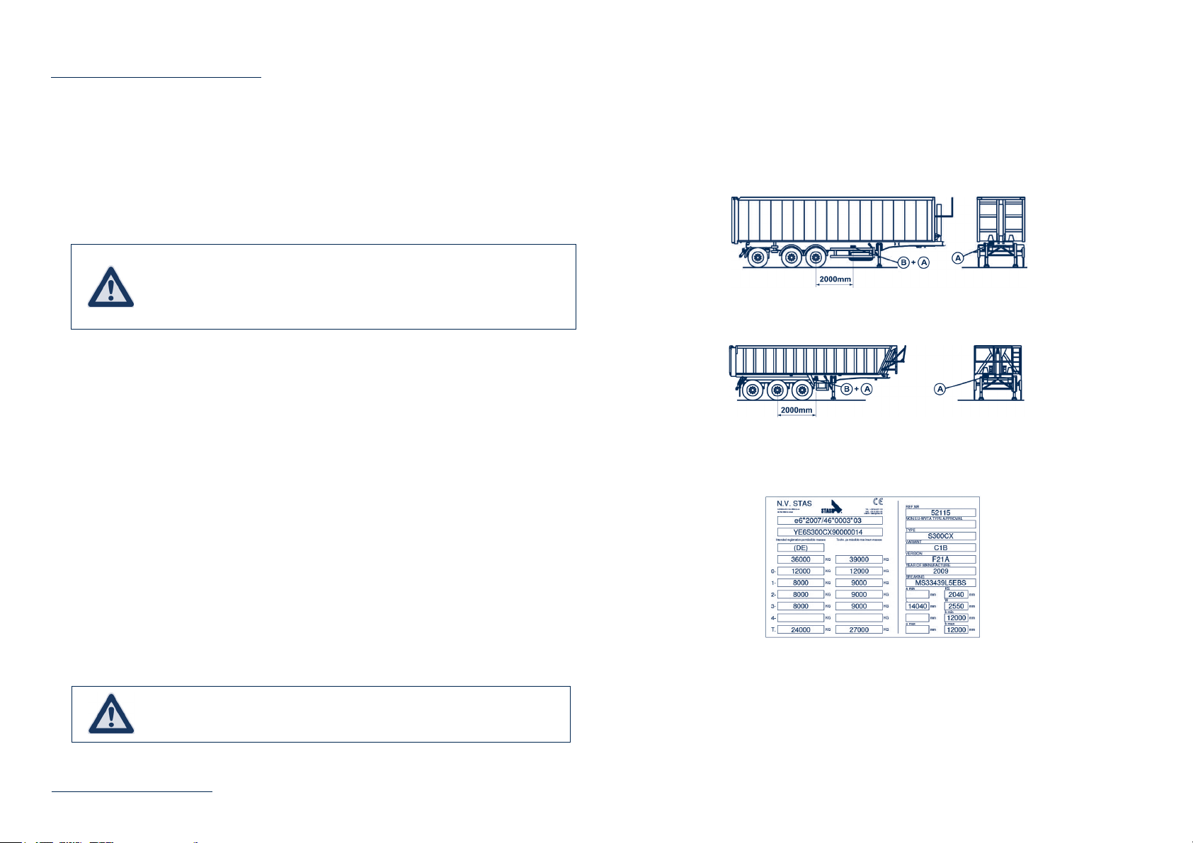
For trailers with symmetrically assembled axles (see Figure 5.1.a), for semi-trailers with not symmetrically as-
sembled axles (see Figure 5.1.b):
A: The identification plate is fixed either to the right in the vicinity of the vehicle identification number or on the
first beam of the chassis on the right-hand side.
B: The trailer identification number is stamped in the chassis to the right at the bottom
4.1. POSITION OF IDENTIFICATION PLATE AND TRAILER IDENTIFICATION NUMBER
Fig 4.1.a. – Position of identification details on a non-self-supporting construction
Fig 4.1.b. – Position of identification details on a self-supporting construction
The identification plate is laid out according to European regulation 76/114/EEC.
4.2. IDENTIFICATION PLATE
Fig 4.2.a. – Identification plate
The plate states (see Fig 4.2.a):
• Manufacturer’s name (1).
• EEC authorization number (2).
• Trailer identification number (3).
• Legally permissible maximum load of the trailer (4a).
• Technically permissible maximum load of the trailer (4b).
• Legally permissible maximum load for each of the axles (from front to back) (5a).
In principle, forklift trucks can drive over all the types of floor slats. Please contact
STAS nv for information regarding permissible load.

STAS - Instructions for use moving floor
9
• Technically permissible maximum load for each of the axles (from front to back) (5b).
• Legally permissible maximum load on the fifth wheel (6a).
• Technically permissible maximum load on the fifth wheel (6b).
• Number national type approval (7).
• Trailer type (8).
• Variant of trailer (9a).
• Version of trailer (9b)
• Year of manufacture (10).
• Brake schedule reference (11).
• Reference number (internal order number)(12)
• Product type (13)
• RT value (only in particular export markets)
• Swing radius (KS).
• Length (L) of trailer.
• Width (W) of trailer.
• a.min and a.max: the minimum and maximum distance between the front of the towing vehicle and the coupling
device.
• b.min and b.max: the minimum and maximum distance between the coupling device and the rear of the trailer.
• Country of registration
C. GENERAL DESCRIPTION MOVING FLOOR
When determining the mass, an evenly distributed load in the trailer is used as
starting point.
The trailer identification number consists of a combination of 17 characters. See § 4.1 for the correct position.
4.3. TRAILER IDENTIFICATION NUMBER
Fig 4.3.a. – Trailer identification number
D. SYSTEM DESCRIPTIONS
1. KINGPIN, FIFTH WHEEL RUBBING PLATE AND FIFTH WHEEL
2. LANDING LEGS
In order to achieve a good and safe driving style for the tractor-trailer combination it is essential to respect the correct
coupling height. The guiding value for the coupling height is stated on the sticker which is attached to the trailer.
Landing legs serve to support the trailer when it has been uncoupled.
There are two types, i.e. the “steel type” and the “aluminium type”. The “steel type” is fitted with a
handle for adjusting the height of the landing leg and is therefore also used for adjusting the correct
coupling height for the trailer when coupling the trailer to a tractor.
Both types of landing legs are fitted with a rolling base which is able to absorb limited forward move-
ment (as a result of loss of pressure in the air bags) provided the trailer is parked on a hard surface.
Fig 1.a. – Fifth wheel rubbing plate with kingpin
Fig 1.b. – Sticker coupling height for 3 axle tractor Fig 1.c. – Sticker coupling height for 2 axle tractor
Fig 2.1.a. – Landing legs
-“aluminium type
If the coupling height is not respected, STAS nv cannot be held liable for any harmful con-
sequences. Please contact STAS nv for information on setting the coupling height for your
tractor-trailer combination, or for further information.
Uncoupling and parking the trailer should be done on a solid and flat surface. Provided the
trailer is fitted with a rolling base, it is NOT necessary to bleed the air suspension prior to
uncoupling.
2.1. DESCRIPTION

STAS - Instructions for use moving floor
10
D. SYSTEM DESCRIPTIONS
2.2. OPERATION STEEL TYPE LANDING LEG
Uncoupling the trailer
Proceed as follows:
• Release the handle.
• Pull the handle out completely in order to select high
speed.
• Turn the handle clockwise until the landing legs touch
the ground.
• Select low speed by pushing the handle inwards.
• Rotate the handle until the trailer is fully supported.
• Return the handle to its storage position (in the clip).
• The landing legs are now in the correct position for the trailer to be uncoupled.
Fig 2.2.1.a. – Storage area for handle “steel type” landing leg
Fig 2.2.1.b. – Handle “steel type” extended
Fig 2.2.1.c. – Handle “steel type” landing leg
Coupling the trailer
Uncoupling the trailer
Proceed as follows:
• Release the handle.
• Select low speed by pushing the handle inwards.
• Turn the handle until the position of the fifth wheel rubbing plate is just below the fifth wheel of the tractor.
• The landing legs are now in the correct position for the trailer to be coupled.
• Don’t forget to return the landing legs to their highest position once the trailer has been coupled.
2.3. OPERATION ALUMINIUM TYPE LANDING LEG
Proceed as follows:
• Ensuring the air suspension of the tractor is in the “driving position”, pull out the locking pin of the landing leg and
hold the leg by the lever on the base. Move the first landing leg down until this touches the ground.
• Repeat the above procedure for the other landing leg.
• Secure the locking pins for both landing legs into the lowest possible hole.
• If, after the landing leg has been secured with the locking pin, there is a 1 to 2 cm gap between the base and the
ground (depending upon the position of the holes), use the air suspension of the tractor to gently lower the trailer
until the landing legs make contact with the ground and are able to take on the load of the trailer.
• The landing legs are now in the correct position for the trailer to be uncoupled.
Fig 2.3.1.a. – “Aluminium type” landing leg
Do not drop the landing leg, but guide it by hand in order to avoid damaging it.
Both landing legs must be lowered to the same length in order to distribute
the load of the trailer evenly.
Ensure the locking pins are always securely in position.
We strongly advise you not to leave the trailer uncoupled from the tractor in a loaded
condition for several days because the weight on the landing legs will become
unbalanced as the air slowly flows out of the air suspension.

STAS - Instructions for use moving floor
11
D. SYSTEM DESCRIPTIONS
Coupling the trailer
As the height of the “aluminium type” landing legs is not adjustable, adjustment takes place via the air
suspension of the tractor.
Once coupling has been carried out, proceed as follows:
• Pull the locking pin out of the first landing leg and position the landing leg as high as possible using the lever on
the base of the landing leg.
• Position the locking pin in order to secure the landing leg in the highest position.
• Pull the locking pin out of the other landing leg and position this also as high as possible using the lever on the
base of the landing leg and reposition the locking pin.
Ensure the locking pins are always positioned securely and cannot be released.
Only WABCO recognized maintenance centres have the appropriate software for main-
taining the braking system and setting the parameters.
For correct maintenance of the brakes or in case of problems with the brakes:
• consult the Internet site www.wabco-auto.com, then click on : “Find WABCO Ser-
vice Locations” , choose your country and make a choice between Service Center
and/or Service Point and/or Dealer and/of WABCO and press “Start search”. The
requested details will be listed.
• contact the STAS nv factories, a recognized representative or dealer appointed by
STAS nv or a STAS nv designated service point.
3. BRAKES
Modern tractors and trailers are expected to be safe, efficient, comfortable and environmentally friendly. An important
step for complying with these requirements is the introduction of an electronically controlled braking system for trailers
or EBS (Electronic Brake System).
EBS allows the continuing best possible synchronisation of the brake forces between the various wheel brakes and
between the tractor and its trailer.
The moving floor trailer is equipped as standard with the WABCO Trailer EBS-E system.
The electronically controlled braking system is equipped as standard with a load sensing brake force adjustment and
anti-locking system (ABS).
The EBS system:
• complies with the legal requirements,
• conforms with directive 71/320/EC,
• conforms with directive UN/ECE-R13,
• complies with the requirements applicable to trailers suitable for transporting hazardous substances.
3.1. GENERAL
1. Voltage supply via ISO7638
2. Control line
3. Supply line
4. Stop light supply via ISO1185 (optional)
5. Pneumatic Extension Module (PEM)
6. Charging valve (integrated in the PEM)
7. Overload protection valve
(integrated in the PEM)
8. Service brake components of the
Tristop®cylinders
9. Tristop®cylinder
10. Reservoirs of the service brake system
11. Reservoir for air suspension
12. Lifting/Lowering valve
13. Red button for actuating the parking brake
14. Black button for releasing the
automatic brake
15. Supporting Bellows
16. Lifting axle valve
17. Levelling valve
18. ABS rotational speed sensors
19. Trailer EBS E Modulator
20. Parking release emergency valve (PREV)
3.2. EBS
System layout
Figure 3.2.1.a. – Example EBS system layout 2S/2M
Depending upon the number of wheel speed sensors (S) and control loops (M), this configuration is described as 2S/2M or
4S/2M.
Extension of the 4S/2M configuration with an EBS relay valve for pressure adjustment of the third axle for trailers is descri-
bed as 4S/3M.
System description
Electro-pneumatic function
The Trailer EBS system is electrically switched on by pin 2 of the socket connection to ISO7638.
If the electrical supply to the ISO7638 plug connection fails, the braking system can be regulated via an optional brake light
facility. Immediately after the Trailer EBS has been switched on, a system check is performed. Two seconds after start-up,
the magnets in the trailer modulator will be attracted or connected one by one. This procedure can be heard by the mag-
nets clicking. The system is ready for operation within 150 ms of being switched on.
Once the Trailer EBS has been switched on, limited ABS function may be available, because
a dynamic check of the ABS sensors will only be carried out once the trailer has driven off for
the first time.

STAS - Instructions for use moving floor
12
D. SYSTEM DESCRIPTIONS
For electro-pneumatic control, the integrated redundancy valve is activated at the start of the braking action, resulting
in the pneumatic command pressure being removed and air tank pressure being applied at the front of the inlet valves
of the modulators. This will enable the brake cylinder pressure to be regulated up to air tank pressure.
For pressure regulation, the current setting is transmitted to the trailer modulator and is then regulated depending
upon the load. In order to adapt the brake forces to the various loads, the bags pressure which is sent to the trailer
modulator via a pneumatic pipe, is measured.
The required deceleration is preferably electronically determined via the CAN data bus connection with the towing
vehicle. If this connection is not available, then the required value is determined using the integrated pressure sensor
in the trailer modulator.
Brake pressure regulation is realised by control circuits with pulse controlled relay valves. For the adjustment of the
brake forces to the load on trailers with air suspension, the spring bags pressure is measured by a pressure sensor.
Pneumatic redundancy
In case of faults in the EBS-system resulting in a partial disconnection, the pneumatic command pressure will go to
the open inlet valve and the closed outlet valve, so that brake pressure is being controlled purely pneumatically, but
without load-sensing control. The ABS control will remain operative for as long as possible. The driver is alerted by a
warning light on the dashboard when a fault is detected.
Electric / electronic system layout
During normal use the trailer modulator is electrically supplied by two wires from the ISO7638 which are each fitted
with a fuse.
For safety purposes, the electrical supply may be regulated via the brake light in order to maintain some regulatory
functions if the electrical supply via ISO7638 should fail.
The data bus connection between the towing vehicle and the trailer modulator is realised via ISO11992. The details
are checked and processed by the trailer modulator.
If the trailer has been coupled to a towing vehicle without EBS, a pressure sensor for determining the required brake
value is integrated into the trailer modulator. The required value is checked for plausibility. Pneumatic redundancy
is realised by the 3/2 magnet valves integrated in the trailer modulator. At the start of each braking cycle, the trailer
modulator energises the magnet valves and removes the redundancy.
Brake pressure of the third axle on a trailer is regulated with an electro-pneumatic EBS relay valve. A brake pressure
sensor and a 3/2 magnet valve have been integrated into this valve. The brake pressure sensor is powered by the
trailer modulator. The actual value is transmitted as an analogue signal.
In order to protect all active sensors from short-circuiting, they are connected to the trailer modulator.
A pressure sensor for monitoring the supply pressure as well as two pressure sensors for the actual brake pressure
have been integrated in the trailer modulator and are powered by the trailer modulator. The actual values are trans-
mitted as analogue signals.
For the determination of the suspension pressure, a pressure sensor has been integrated into the trailer modulator,
and a pneumatic pipe is led from the trailer modulator to the bags.
For controlling wear on the brake pads, they have been fitted with indicators for the end value, the signals of which
are monitored by the trailer modulator and transmitted to the towing vehicle.
System faults are recognised by the trailer modulator and stored in accordance with a fixed fault matrix in the diag-
nostic memory.
The trailer modulator has the following connections:
A - Pneumatic connection:
TEBS E Modulator with PEM
1. Supply (to the reservoir “Brake”)
1.1 Supply “Air Suspension”
(to air suspension valve, rotary slide valve,
lifting axle valve or ECAS block)
2.1 Braking pressure (to the brake cylinder)
2.3 Tristop®cylinder (to the Tristop®cylinder(12))
4 Control pressure (to PREV 21)
5 Bellows pressure (to air suspension bellows)
1 Supply (to the reservoir “Brake”)
2.2 Braking pressure (to the brake cylinder)
2.3 Tristop®cylinder (to the Tristop®cylinder(12))
4.2 Control pressure (to PREV 22)
1 Supply (o the reservoir “Brake”)
2.4 Test connection “Brake”
Figure 3.2.2.a. – Pneumatic connection

STAS - Instructions for use moving floor
13
D. SYSTEM DESCRIPTIONS
B - Electronic connection:
Figure 3.2.2.b. Electronic connection
POWER Connection ISO 7638 7 pin voltage supply
SUBSYSTEMS Connection for SmartBoard
MODULATOR Connection for 3rd modulator (4S/3M or 4S/2M+1M)
IN/OUT Stop light supply or TCE
ABS – C - D ABS sensoren main
ABS – E - F ABS sensoren additional
GIO 1-7 Multifunctional ports IN-OUT
Roll Stability Support (RSS) (optional)
There are various definitions relating to a vehicle rolling over:
• A vehicle may roll over if the critical lateral acceleration is less than the maximum friction between the tyres and the
road.
• The critical lateral acceleration for rolling over is the limit value of the force, which is allowed to affect a vehicle late-
rally on the driving direction before the vehicle rolls over.
• The maximum friction between the tyres and the road is the limit value of the force, which is allowed to affect a
vehicle laterally on the driving direction, before the vehicle slips.
• Trailers often have a relatively high centre of gravity and are therefore extremely likely to roll over when tight bends
are being taken at too high speeds. For trailers, the critical lateral acceleration may be lower than that of the tractor.
In contrast to the rolling over risk of the tractor, the driver often notices this too late where the trailer is concerned
in order to be able to take corrective action (by braking for instance). With the aid of the RSS function, the imminent
risk of the trailer rolling over is recognised and corrected by automatic braking. This reduces the risk of rolling over.
The RSS function uses the available details of the Trailer EBS:
• wheel speed,
• information on the load,
• information on the required declaration,
• information from the sensor for lateral acceleration integrated in the EBS modulator.
RSS recognises the risk of rolling over as a result of a strong relief in pressure on the wheels in the inside bend. When the
calculated critical lateral acceleration of the trailer is exceeded, a low testing pressure is temporarily applied. Duration and
height of the pressure depend upon the current critical lateral acceleration. The risk of rolling over is recognised using the
wheel reaction during test braking.
When the risk of rolling over is detected, high pressure braking on the wheels of the trailer in the outside bend will take
place in order to prevent rolling over. The brake pressure for the wheels in the inside bend will remain mainly unchanged,
depending upon any ABS regulation.
When braking in accordance with RSS, the brake lights do not illuminate because the brake light
can only be activated by the tractor whereas RSS braking is controlled by the trailer.
As a result of the RSS control, the physical limits cannot be exceeded. If there is a further increase
in lateral forces on the trailer, despite automatic braking and the resulting retardation, and the
reduction in lateral acceleration is too slow, the trailer combination may still roll over even if RSS
is activated.
An RSS adjustment starts during a driving situation with partial or no braking. If the driver brakes sufficiently (retardation
above the level of the RSS retardation), RSS is not activated. If, during an RSS adjustment of the trailer which has already
started, the tractor indicates a pneumatic or electric braking value, then RSS adjustment will be cancelled as soon as the
braking value of the tractor is higher than that of the RSS. The braking pressure in the trailer is then adjusted to the requi-
rements of the tractor up to the end of the braking operation.
During driving the following are compensated: up to 9% variation in tyre circumference, misalignment of modulator up to 3
degrees on the longitudinal axle of the vehicle plus the offset tolerance of the lateral acceleration sensor. The RSS function
may be out of operation or react slowly up to the level of compensation. The warning light may even go out before the RSS
is functioning at its best.
When trailers are driving without any pressure in the air bags, it may be that the RSS does not detect any risk of rolling
over due to a lack of information on the load.
Once faults are detected, the RSS is permanently switched off and the warning light is activated. In this instance, correct
RSS functioning can no longer be guaranteed.

STAS - Instructions for use moving floor
14
D. SYSTEM DESCRIPTIONS
Standstill function
On a stationary trailer (speed < 1.8 km/h) with a command pressure of more than 3.5 bar, the electro-pneumatic brake
pressure switches to pneumatic brake pressure after 5 seconds. This function serves to prevent unnecessary use of
electricity when the combination is stationary with the handbrake on and the ignition on. This function is deactivated
when driving commences.
Emergency brake function
In order to be able to exert maximum brake force at all times, an emergency brake function has been integrated. If the
brake pressure value desired by the driver corresponds to more than 90% of the available supply pressure, a so-called
emergency stop, the brake cylinder pressures will be increased up to the supply pressure. This function is also opera-
tive when a spring bag of the suspension has burst.
Verification of supply pressure
The supply pressure to the trailer is verified by the EBS. If pressure drops below 4.5 bar then the driver is alerted by
the red and yellow warning lights. Once the pressure of the air pressure braking system has been corrected and the
pressure of the trailer exceeds 4.5 bar, the lights will go out. If the supply pressure drops below 4.5 bar during driving,
this will be stored as a fault.
Kilometre indicator
The Trailer EBS is fitted with an integrated kilometre indicator, which measures the distance covered when the EBS
system is functioning. Two separate functions are available:
• The total number of kilometres indicates the total amount of kilometres driven since the system was put into
operation. This value is saved on a regular basis and can be read with the aid of the various diagnostics equip-
ment or SmartBoard.
• A tripometer is also available. This can be reset to zero at any time. In this way the number of kilometres
between two maintenance inspections can be determined or the number of kilometres driven since a particular
time. Diagnostic equipment or SmartBoard is used to read and reset the tripometer.
Special calibration is not required. The calibration factor is calculated using the tyre circumference and the number of
teeth in the field system, which are entered during the final inspection of the Trailer EBS.
The kilometre indicator requires an electrical supply. It will therefore only function when the Trailer EBS is electrically
connected and is not tamper-proof.
Service signal
This function may be activated using diagnostic equipment. If this function has been activated, a warning light can be
set to be activated after a certain number of kilometres, selected with the aid of the diagnostic equipment, have been
covered. This warning light will illuminate the first time the ignition is switched on after the selected number of kilome-
tres have been covered and will flash eight times. The flashing will repeat itself every time the ignition is switched on
and will help to remind the driver the trailer is due for a service, etc.
The service signal may be reset. After resetting, the set service interval as described, will be re-activated.
This function is not switched on at the time of delivery.
Operation hour counter
The elapsed operation time is stored in the memory and may be read via the diagnostic socket or SmartBoard.
The counter for the operational hours only functions when the Trailer EBS is electrically connected and is therefore not
tamper-proof.
ILS (Integrated Load Switch) (optional)
If the trailer is equipped with lift axle(s), these may be automatically controlled, independently from the actual axle load, by
the Trailer EBS. To this end, an electrical axle lift valve should be connected to the GIO plugs of the trailer modulator.
The axle load at which the lift axle is lowered is calculated using the pressure present in the air spring bags and using the
details of the bags pressure and the axle load in laden and unladen conditions, which have been laid down in the parame-
ters.
The trailer speed at which raising the lift axle(s) can be carried out, lies between 0 and 30 km/hour. Diagnostic equipment
is used to set the parameters.
When a fault is detected in the axle load sensor, the lift axle will be lowered at speeds between 5 and 30 km/hour and will
not be activated at a speed below 5 km/hour.
Only ABS sensors e and f may be connected to the lift axle. ABS sensors c and d should always be connected to the main
axle.
Lift axle traction help (optional)
A lift axle traction help may be set up on trailers with a first axle as the lift axle or with the first axle with axle deflation (air
suspension dump valve). The value for the axle load for the lift axle traction help should be no more than 30% above the
maximum permissible axle load and should be determined by the manufacturer. Once a speed of 30 km/hour has been
reached, the axle will come back down or the first axle will be inflated.
The TH version (an axle lift valve) means that the lift axle may be lifted or that the air suspension dump valve can be
deflated to help driving off, when the permissible bags pressure set in the parameters is not exceeded after lifting. If the
permissible pressure is exceeded during driving off, the lift axle traction help is interrupted and the lift axle will come back
down or the air suspension dump valve will be inflated.
Please note : The operation first axle with axle deflation (air suspension dump valve) does not work independently
or separately of the lift axle traction help.
The lift axle traction help (or forced lifting) is being activated :
• either through an impulse button connected to the power supply (+24 V) or minus (0 V) and on a GIO of the modula-
tor (with cable) and if the parameters have been set accordingly. The impulse on the button needs to be between 0,1
and 5 seconds.
• or by pushing 3 times the brake pedal if the parameters have been set accordingly on the GIO of the modulator
(without cable).
• or through the SmartBoard if the parameters have been set accordingly.
In order to disconnect the lift axle traction help :
• either when the impulse on the button is more than 5 seconds (with cable).
• or by pushing again 3 times the brake pedal (without cable).
• or through the SmartBoard.
Wear indicator (optional)
Up to 6 indicators for monitoring wear on the brake pads can be connected to the electronic system. The wear indicators
(a wire integrated into the brake pad) measure the wear on both brake pads. All indicators are connected in series and
connected to the wear input in a voltage distributor. The driver is alerted via the ABS warning light, shortly before and when
the limit of wear has been reached.
During technical inspection and verification, it should be possible to lower the axle when the
trailer is unladen. This may be done by switching off the trailer ignition or through the Smart-
Board operation. The axle is then lowered and will remain in this position regardless of the
load. The axle will only be raised when the speed of the trailer exceeds 15 km/hour.

STAS - Instructions for use moving floor
15
D. SYSTEM DESCRIPTIONS
The warning is interrupted when the trailer exceeds a speed of 7 km/hour. In case of system faults, the ABS warning
light is permanently activated.
The corresponding information is simultaneously transmitted to the tractor-trailer interface and can be displayed on
the display.
The system automatically detects when new wear indicators have been installed after the brake pads have been re-
placed. All warning lights will be de-activated after approx. 2 minutes (switch on ignition for a minimum of 2 minutes).
The warning light will only go out when the ignition is switched on again.
The last five replacements of the brake pads (position of kilometre indicator and operational hours when the second
warning phase and replacement of brake pads have taken place) are stored in the ECU and can be read using the PC
diagnostics.
The connecting points on the trailer are located at the front. The command line is colour coded yellow and the supply
line is colour coded red.
WARNING LIGHT
Warning phase 1
When the wire in the indicator has been worn down
during braking (> 3 braking operations), short-circui-
ting towards earth (earth connection between brake
and chassis is essential) occurs and warning phase 1
is activated. During the first warning phase, the ABS
warning light will flash 4x (1 cycle) once the ignition has
been switched on.
Warning phase 2
When the wire in the indicator has been worn through
for 4 minutes, a voltage of 4.5 volts is measured in the
wear input and warning phase 2 is activated. During the
second warning phase the ABS warning light flashes 4x
4 cycles (total of 16 times), once the ignition has been
switched on.
3.3. BRAKE CONNECTION
Figure 3.3.a. – Brake system connection
• When uncoupling the connecting hoses, the brakes are automatically activated.
• Once the air pipes have been disconnected, the connecting points should be pro-
tected against contamination by water or dust by placing the lids of the connections
over the apertures.
• The parking brake is NOT automatically set once the command and supply air pipes
have been disconnected.
• Repairs to the brake system may only be carried out by qualified engineers.
• Any components in the brake system which need replacing, should always be re-
placed by original components.
If the ISO7638 cable is not connected, the ABS and additional functions will NOT be operative.
In this case, the brake system will operate as a conventional brake system.
Trailers equipped with the EBS-E brake system may only be coupled to tractors with
either:
• an ISO7638-1996 electrical connection (7-pin, 24V, CAN-databus),
• an ISO7638-1985 electrical connection (5-pin, 24V, no CAN-databus).
Figure 3.3.b. – 7-pin socket (left) and 5-pin socket (right)
4x 4x 4x 4x
ON
OFF
Contact ON Time
4x 4x 4x 4x
ON
OFF
Contact ON Time

STAS - Instructions for use moving floor
16
D. SYSTEM DESCRIPTIONS
See also “Wear indicator (optional)” on page 16.
It may be possible that a tractor-trailer combination does not brake properly. Upon further investigation, it is usually
found that in case of a trailer with drum brakes, the brake lining has been glazed or burnt and the brake drums have
torn. In case of a trailer with disc brakes, it appears the brake pads have completely worn after a limited number of
kilometres and the brake discs show deep grooves.
For articulated vehicles, the tractor as well as the trailer are conform to European directives or to the regulations of
the United Nations nowadays. In practice however, it appears that on a combination of these two, optimum braking is
not performed. Nevertheless, it is most important that each of the vehicles takes on its share of the braking force in a
correct manner and under any loading conditions.
A synchronisation of the brake system (see § 3.5) on the tractor and the trailer prevents these problems.
This brake synchronisation, which should be carried out by the tractor manufacturer, is recommended in order to
obtain optimum brake force distribution and an optimum wear pattern between the tractor and the trailer.
Damage and wear as a result of poor brake synchronisation will not be accepted under warranty under any circum-
stances. We therefore recommend a brake synchronisation is performed and the synchronisation report is kept in a
safe place. Always ensure that the report clearly states the details of the tractor and the trailer, including the date on
which the synchronisation was performed.
3.4. PREVENTION OF PREMATURE BRAKE WEAR
3.5. BRAKE SYNCHRONISATION
Also consult the additional publications which have been supplied with the trailer.
Between the first 2000 and 10000 km, and after each change of tractor,
a brake synchronisation is recommended.
Please also refer to the additional documentation supplied with the trailer.
3.6. BRAKE PLATE
As the braking system is fitted with EBS, the brake plate has been replaced by a
sticker. The parameters of the EBS controlled brake system can be found on this
sticker.
Aangezien het remsysteem met EBS is uitgerust is het remplaatje vervangen door een zelfklever. Op de zelfklever
worden de parameters van het door het EBS gestuurde remsysteem teruggevonden.
3.7. DRUM BRAKE
The trailer brake operates according to the general drum brake principle. The force of the brake cylinder (1) starts up the
brake shaft via brake rods (2,3) in a rotary movement. The cam (4) at the end of the brake shaft spreads the brake pads (5)
and in this way pushes them against the inside of the brake drum (7) resulting in an effective braking force.
When the brake pedal is released, the cylinder pressure on the rods is removed and the brake shaft and cam return to
their original position. The brake pads are also returned to their original position by return springs (6). The brake force is
removed.
Figure 3.7.a. – Drum brake
3.8. DISC BRAKE
When the brake pedal is operated, the connecting rod (1) of the brake cylinder pushes on the lever (2) of the disc brake.
The wheel which is eccentrically mounted on bearings (3) transfers the force to the bridge (4). The clamping force impacts
upon the inner brake lining via the threaded rod and the piston (5). The brake lining (6) pushes itself off against the brake
disc (7). The reactive force which is generated on the brake saddle (8) is transferred to the opposing brake lining resulting
in this also being pushed against the brake disc with an equal force and generating an effective braking force.
Figure 3.8.a. – Disc brake
Figure 3.6.a. – EBS brake system sticker

STAS - Instructions for use moving floor
17
D. SYSTEM DESCRIPTIONS
Figure 3.9.a. – Spring brake cylinder
The control unit for the parking brake is located on the side of the trailer, together with the raising and lowering valve
and the loading gauge.
The red control button for the spring brake cylinders can be found on the left hand side of the control unit (see Figure
3.9.b.).
3.9. PARKING BRAKE – SPRING BRAKE CYLINDERS
The parking brake with spring brake cylinders operates as follows:
• As the pneumatic pressure in the spring brake cylinder disappears, the spring is released and generates a brake
force in this way.
• As the pneumatic pressure builds up in the spring brake cylinder, the force of the spring is removed and the
brake force is removed.
Fig 3.9.b. – Control unit for parking brake with control button
Operation of the parking brake can be summarised as follows:
• Pull out the red button to activate the trailer parking brake.
• Push the red button to switch off the trailer parking brake.
• Once the parking brake has been switched off, it is NOT possible to drive off im-
mediately. The pressure in the spring brake cylinder needs to rise first before the
parking brake is released.
• Ensure the parking brake is sufficiently tightened before leaving the trailer unman-
ned.
• It is advisable to place a wheel chock in front of or behind the wheels for additional
protection.
• Always park the trailer on a horizontal and stable surface, NEVER on an incline.
Figure 3.10.a. – Control unit emergency brake with
control button
3.10. EMERGENCY BRAKE
This function is used when the trailer is not connected to the tractor and it is necessary to move the trailer using a fork lift
truck for instance.
When the red air pressure pipe between the tractor and the trailer is uncoupled, the brake system on the trailer will
automatically go into the braking position so that, in principle, the trailer cannot be moved. With the aid of the emergency
brake, the trailer can still be moved without the tractor.
The control unit for the emergency brake is located on the side of the trailer, together with the raising and lowering valve
and the loading gauge.
The black control button for the service brake is located on the right hand side of the control unit (see Figure 3.10.a.).
Operation of the emergency brake can be summarised as follows:
• Push the black button to activate the emergency brake in order to move the trailer (using a fork lift truck for
instance).
• Pull out the black button to re-activate the service brake for the trailer.
Figure 3.10.b. – Operation of emergency brake
Use of the emergency brake requires a pressure of more than 4 bar in the pneumatic
circuit.

STAS - Instructions for use moving floor
18
D. SYSTEM DESCRIPTIONS
4. AIR SUSPENSION
The air suspension of the trailer ensures the chassis of the trailer is spring-mounted with regard to the axles of the
trailer and is able to absorb the shocks in this way. The pressure in the spring bags is regulated automatically in such
a way that for each load, maximum driving comfort and minor movement of the superstructure is obtained. This also
results in good road holding and little tyre wear.
4.1. GENERAL 4.2. RAISING AND LOWERING VALVE
Figure 4.1.a. – Air suspension
Figure 4.2.a. – Raising and lowering valve
The valve for raising and lowering on a trailer with air suspension allows the height of the trailer chassis to be adjusted
with a view to loading and/or unloading the trailer.
This valve is used to adjust the difference in height between the axles and the chassis of the trailer.
The raising and lowering valve has 5 positions:
• Position for lowering the chassis to its lowest position (lever clockwise in outer position).
• Position for stopping the lowering movement.
• Driving position.
• Position for stopping the raising movement.
• Position for raising the chassis to its highest position (lever anti-clockwise in outer position).
The position of the raising and lowering valve may only be changed to another position
from the driving position during loading and unloading.

STAS - Instructions for use moving floor
19
D. SYSTEM DESCRIPTIONS
General
4.3. SmartBoard
Certain functions are not standard. Those can be obtained through options
Odometer
Tire monitoring
Road finisher brake
Messages
Immobilizer
Air suspension Extra's
Vehicle inclination Language
Lining wear Axle load indication Switch options

STAS - Instructions for use moving floor
20
D. SYSTEM DESCRIPTIONS
The electronic kilometre indicator can be read on the SmartBoard (see Figure 4.3.1.a.).
The electronic kilometre indicator is used to:
• verify in a simple manner how many kilometres the trailer has travelled,
• plan the maintenance of the trailer by the number of kilometres travelled.
Odometer: kilometre recorded by SmartBoard = Total number of kilometres (independent of the power supply)
Mileage: number of kilometres recorded by EBS (with power supply)
Trip EBS: trip mileage EBS (with power supply – can be set on 0 (only with PC))
Trip: trip mileage counter SmartBoard (with power supply – can be set on 0 with SmartBoard).
The SmartBoard gives an “indication” of the total axle load or the load on the axles separately (see figure 4.3.1.a.).
Calibration
Pressure sensor calibration
4.4. LOAD INDICATION THROUGH SMARTBOARD AND ANY POSSIBLY CALIBRATION
Electronic kilometre indicator through SmartBoard
It is strictly forbidden to exceed the maximum bags pressure stated on the brake plate
(see §3.6 3.6).
During calibration, the parking brake and service brake must be released.
Rolling vehicle
Position the vehicle on an even surface and secure it against rolling away with use brake
wedges. Only use approved devices to jack up and secure the vehicle.
Risk of injury due to brake action while working on the brake
Attach a clearly marked note on the steering wheel saying that work is being performed
on the vehicle and that the brake must not be touched.
The SmartBoard provides the option to calibrate the pressure sensor to improve the accuracy of the axle load indica-
tion of Trailer EBS E.
This will improve the accuracy of the axle load indication. The more accurate the vehicle weight is determined and the
pressure sensors are calibrated, the more exact the axle load is displayed. In case of a wrong calibration the axle load
indicates wrong values!
The actuation of brake pressures is unaffected by this calibration, these values apply to parameter settings provided
by vehicle manufacturer.
Calibration points
The larger the weight difference between individual calibration points, the more exact the axle load indication will be.
The calibration point “partially loaded” is an option and not necessarily used.
• Empty
• Partially loaded (optional)
• The vehicle weight in the partially loaded condition should be the midpoint between vehicle weight in empty and
fully loaded condition.
• Loaded
Preconditions
• Trailer EBS E1 with software version from TE14013 upwards
• SmartBoard with software from SB010207 upwards
Calibration on the semi-trailer
Determine the weight of semi-trailer is unladen, partially laden (optional) and laden weight using calibrated weighing
device.
Ensure that all axles of the semi-trailer are located on the weighing device.
• Select the menu <extras> <settings> <sensor calibration>.
• For vehicles with raised lifting axle(s) you will be requested to lower them.
• Lower the lifting axle(s) by pressing button <arrow right>.
• The calibration will continue when all lifting axle(s) are lowered.
• Select the menu item <calibrate unladen.> and enter the weight of unladen semi-trailer.
• Button <arrow right>: changes the digit position
• Button <OK>: changing the value
• Button <back>: confirmation of input
• Confirm saving the entered calibration data by pressing the <OK> button.
• A successful calibration is indicated by displayed icon with check.
• Repeat the last two action steps for the partly loaded (optional) and the fully loaded semi-trailer.
• To do this, select the corresponding menu items <calibrate partly laden.> and <calibrate full laden>.
5. WHEEL ACCESSORIES
5.1. TYRES AND RIMS
5.2. SPARE WHEEL AND SPARE WHEEL CARRIER
All wheels and tyres mounted on the trailer are identical. A number of options with regard to make, size, offset and profile
of wheel/tyre are available, but these should always comply with the technically permissible axle loads, the load-speed
index and the brake schedule.
The spare wheel is located as standard in the single spare wheel carrier on the passenger side of the vehicle. In order to lift
the spare wheel from its carrier, remove the safety bar which retains the spare wheel in position. An optional double spare
wheel carrier may be fitted.
In the interest of safety it is extremely important to respect the correct tyre pressures.
Driving on tyres with insufficient pressure causes an abnormal rise in temperature which damages components of the tyres.
This damage is irreversible and will in due course unavoidably lead to flat tyres. The consequences of insufficient tyre pres-
sures are not always immediately visible and may only become apparent long after the tyre pressures have been corrected.
The valve cap is essential for complete air-tightness and for protection of the inner valve.
Tyre pressures are stated on the sticker located on the side of the trailer at the height of the
first axle.
The maximum load is 140 kg for a single spare wheel carrier and 250 kg for a double spare
wheel carrier.
The spare wheel should be securely fastened to the spare wheel carrier at all times in order
to avoid damaging, coming loose or losing the spare wheel.
Figure 5.2.a. – Single spare wheel carrier
This manual suits for next models
8
Table of contents
Other STAS Utility Vehicle manuals


