Status Pro R280 User manual

R280
Bluetooth Laser Receiver
Instruction Manual
Another fine solution by

2Status Pro – R280 Instruction Manual
R280
Instruction Manual – English
Laser Receiver R280
(BG 831500)
Software version V 1.00
We woul like to congratulate you on the purchase of your Status Pro R310 Laser receiver.
Before initial usage you shoul carefully rea the safety instructions as well as the user
gui elines containe in this manual. We wish you every success when using this
Measurement Instrument.
Please note: User Manuals can be amen e when improvements or changes to the pro-
uct range have been carrie out. Use the link below to make sure you have the most up
to ate version of your User Manual: www.statuspro.com.

Status Pro – R280 Instruction Manual 3
CONTENT
Content
1. SAFETY INSTRUCTIONS . . . . . . . . . . . . . . . . . . . . . . . . . . . . . . . . . . . . . . . . . . . . . . . . . . . . . . . 3
1.1 Class of Laser . . . . . . . . . . . . . . . . . . . . . . . . . . . . . . . . . . . . . . . . . . . . . . . . . . . . . . . . . . . 3
1.2 Stan ar s . . . . . . . . . . . . . . . . . . . . . . . . . . . . . . . . . . . . . . . . . . . . . . . . . . . . . . . . . . . . . . . 4
1.3 A vice on batteries / rechargeable cells . . . . . . . . . . . . . . . . . . . . . . . . . . . . . . . . . . . . 4
1.4 Instrument care . . . . . . . . . . . . . . . . . . . . . . . . . . . . . . . . . . . . . . . . . . . . . . . . . . . . . . . . . . 5
1.5 Maintenance . . . . . . . . . . . . . . . . . . . . . . . . . . . . . . . . . . . . . . . . . . . . . . . . . . . . . . . . . . . . . 5
1.6 Calibration an repair . . . . . . . . . . . . . . . . . . . . . . . . . . . . . . . . . . . . . . . . . . . . . . . . . . . . . 6
1.7 Liability exclusion . . . . . . . . . . . . . . . . . . . . . . . . . . . . . . . . . . . . . . . . . . . . . . . . . . . . . . . . . 6
2. GETTING STARTED . . . . . . . . . . . . . . . . . . . . . . . . . . . . . . . . . . . . . . . . . . . . . . . . . . . . . . . . . . . . . 7
2.1 Power Supply . . . . . . . . . . . . . . . . . . . . . . . . . . . . . . . . . . . . . . . . . . . . . . . . . . . . . . . . . . . . 7
2.2 Assembly . . . . . . . . . . . . . . . . . . . . . . . . . . . . . . . . . . . . . . . . . . . . . . . . . . . . . . . . . . . . . . . . 8
3. HANDLING . . . . . . . . . . . . . . . . . . . . . . . . . . . . . . . . . . . . . . . . . . . . . . . . . . . . . . . . . . . . . . . . . . . 10
3.1 Button Panel of the R280 . . . . . . . . . . . . . . . . . . . . . . . . . . . . . . . . . . . . . . . . . . . . . . . . . 10
3.2 LED Signals from the R280 . . . . . . . . . . . . . . . . . . . . . . . . . . . . . . . . . . . . . . . . . . . . . . . . 11
3.3 R280 Monitor Control Software . . . . . . . . . . . . . . . . . . . . . . . . . . . . . . . . . . . . . . . . . . . . 12
4. MEASUREMENTS . . . . . . . . . . . . . . . . . . . . . . . . . . . . . . . . . . . . . . . . . . . . . . . . . . . . . . . . . . . . . 13
4.1 Setting up a laser plane . . . . . . . . . . . . . . . . . . . . . . . . . . . . . . . . . . . . . . . . . . . . . . . . . . 13
4.2 Checking an calibrating the T330 Self-Levelling function . . . . . . . . . . . . . . . . . . . . 12
. TECHNICAL DATA . . . . . . . . . . . . . . . . . . . . . . . . . . . . . . . . . . . . . . . . . . . . . . . . . . . . . . . . . . . . . 16
6. ACCESSORIES . . . . . . . . . . . . . . . . . . . . . . . . . . . . . . . . . . . . . . . . . . . . . . . . . . . . . . . . . . . . . . . . 18
7. PRODUCTS AND SERVICE . . . . . . . . . . . . . . . . . . . . . . . . . . . . . . . . . . . . . . . . . . . . . . . . . . . . . 22
8. MEMO . . . . . . . . . . . . . . . . . . . . . . . . . . . . . . . . . . . . . . . . . . . . . . . . . . . . . . . . . . . . . . . . . . . . . . . 23
1. Safety Instructions
1.1 Class o Laser
The laser light emitte from a Status Pro Laser has an Output Rating of < 1,0 mW.
The Laser is place in the category „Class 2“ an is classifie as safe for the use as
a measurement instrument. There are however a few safety aspects to be observe :

1.2 Standards
All Status Pro Laser an Receiver Instruments are evelope an manufacture
accor ing to the following CE Stan ar s:
•EN 55 011
•EN 55 022
•EN 61 000-4-2
•EN 61 000-4-3
•EN 60 335
1.3 Advice on batteries / rechargeable cells
If the equipment is being store for a longer perio of time or being powere using Mains,
then the batteries shoul be remove to prevent amage of the instrument through
leakage.
4Status Pro – R280 Instruction Manual
SAFET INSTRUCTIONS
R280
Caution!
•Do not stare into the laser beam.
•Do not point the laser beam at other people.
•Observe the local safety gui elines on Site an if in oubt consult
the Site safety Engineer.
•Do not use the equipment in amp or moist locations.
•Ensure sha ing of the equipment against irect sunlight or heat
sources.
•Flui s or rain as well as extreme temperature con itions may
amage the equipment.
Note
Do not violently shake the Laser or other sensors an always
protect against falls. This can amage the structure or the optics
of the instrument resulting in false measurements.
Do not touch rotating parts when in use!

When using rechargeable cells always observe the specific charging proce ures for the
cells.
Rechargeable cells can be recharge aroun 1000times when treate correctly, but there
is no guarantee!
1.4 Instrument care
Your measurement instrument is esigne for use in an in ustrial environment an can
withstan water splashes or light spray as well as ust. Clean the equipment using a soft
cotton cloth an a mil soap solution. Laser apertures as well as well as sensor areas
shoul only be cleane using a soft, ry an ust-free cloth. Do not use paper towels to
clean glass surfaces as they coul scratch. Avoi contact with grease, oil or oil-base
solutions when han ling the equipment.
1.5 Maintenance
The mechanical components of your equipment are prone to natural wear an tear! If the
Instrument appears to have a technical efect, contact the Manufacturer. Do not try to
Status Pro – R280 Instruction Manual
SAFET INSTRUCTIONS
Caution!
Do not try to recharge normal batteries. Do not expose batteries
or rechargeable cells to fire or excess heat (Danger of explosion).
Do not mix batteries an rechargeable cells.
Always use batteries an cells of the same kin .
Do not mix ol an new batteries or cells.
Note
Help to protect the environment! Empty batteries o not belong in
the househol waste isposal system. Only eposit empty or
amage cells at a collection point specially esigne for this
purpose.

6Status Pro – R280 Instruction Manual
SAFET INSTRUCTIONS
R280
repair or open the sensor casing. Attempte repairs through unauthorise personnel
makes the guarantee null an voi ! Always store the equipment un er ry con itions an
use the case for transportation.
To ensure trouble-free processing, simply fill in the form you will fin using the following
link: www.statuspro.com/machine_geometry/service_support/calibration_repair
1.5 Calibration and repair
To guarantee measurement accuracy, an reliable operation of your Status Pro
Measurement System, it is of utmost importance that the recommen e Service Intervals
be a here to. The System shoul be checke for serviceability, an re-calibrate by the
Status Pro workshops every 12 months.
Within the scope of the service checks, the complete system will also be examine for
possible wear or amage, as well as receiving any software up ates. The ate of the next
service check for your equipment is stampe on the Status Pro calibration sticker.
To ensure trouble-free processing of the service an calibration checks, simply fill in the
form you will fin using the following link
www.statuspro.com/machine_geometry/service_support/calibration_repair.
1.6 Liability Exclusion
The Status Pro GmbH oes not accept responsibility for amage incurre through incor-
rect use or han ling of the equipment. To ensure correct usage, a foun e knowle ge of
the equipment is essential. It is of the utmost importance that you rea an un erstan
the Han book!
No responsibility will be accepte for amage incurre through ignorance or isregar ing
of the operating instructions.
Advice
To be able to i entify the equipment when seeking a vice always
quote the serial number of the equipment. The Manufacturer oes
not accept any responsibility for amage incurre through incorrect
maintenance carrie out by non-authorise personnel.

2. Getting started
2.1 Power Supply
The R280 can only be powere using a Type BT 800071 re-chargeable cell. A completely
charge cell will provi e enough energy for aroun 8 hours usage. A ischarge cell can
be recharge in approximately 1,5 hours using the external charger (BT 800072) . Constant
operation is possible if a secon cell is available (optional extra).
The battery pack (III) can be accesse by opening the rear cover (I) . To open the cover,
simply pull, using the two in entations(II), the cover is hel in place with a magnet.
The battery is place in the housing with the contacts
pointing to the mi le of the sensor. The battery is place
correctly when the rear cover closes without any resi-
stance. Due to the shape of the housing it is normally
possible to fit the cell incorrectly.
Status Pro – R280 Instruction Manual 7
GETTING STARTED
I
II
III
IV

2.2 Assembly
The R280 Laser receiver has two M8 threa s (V) on the un ersi e an two on the top si e.
The threa s enable correct fitting of the Magnet A apter Typ BG 831510, usually use
when measuring objects. The A apter consists of a switcheable magnet (VII) an a revol-
veable column (VIII). The a apter can be fitte at either en of the sensor.
8Status Pro – R280 Instruction Manual
GETTING STARTED
R280
Please ollow instructions below:
➜Cell fitte correctly (Contacts eepest position in the housing)
➜For use solely with cell type: BT 800071
➜Remove cell before prolonge storage (Danger of corrosion)
V
VI
VIII
IX
VII
A apter BG 831510

When fitting the A apter to the un ersi e of the sensor, the locating owel (IX) an the
rilling (VI) ensure correct positioning of the sensor . When fitting the A apter to the
above si e, the locating owel has to be remove (M3 Allen Screw).
The BG 831510 A apter facilitates rotation of the sensor in the Axis an is play-free, enab-
ling accurate measurements.
Alternatively, the A apter BG 831550 (X) can be mounte to the sensor enabling use of the
M8 measuring a apter (BT 948336) (XI). The measuring a apter (XI) is fitte into the recess
in the A apter (X) an secure with the knurle screw (XIII). The asymmetrical groove on
the M8 A apter guarantees a constant an repeatable fitting of the sensor an thus, sen-
sor height.
The measurement a apter (XI) with its 8mm threa (XII) on the un ersi e can be fitte to
the larger switcheable magnet (BT 943092) or irectly screwe into existing or purpose
cut threa s on machine or other objects. The permanent fitting of the a apter allows peri-
o ic or constant measurements on machines or buil ings for example, whereby the sen-
sor oes not have to stay in place if perio ic an not constant measuring is require .
To rotate the R280 in the laser axis when using the BG 831550 (X) A apter, simply loosen
the knurle screw (XIII), rotate as wishe an then re-tighten the knurle screw.
Remember, the R280 shoul always face the T330 in an orthogonal fashion.
Status Pro – R280 Instruction Manual 9
GETTING STARTED
A apter
BG 831550
A apter complete with
M8 A apter mounte on
the switcheable
Magnet BT 943092
M8 A apter
BT 948336
X
XI
XII
XIII
3. Handling
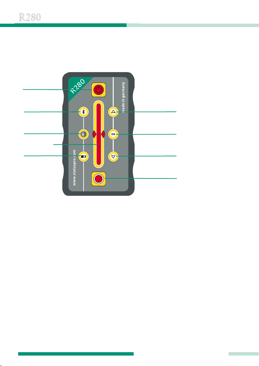
3.1 Button Panel o the R280
To turn on the R280 simply press the On/Off button, to turn Off press an hol for 1 secon
or longer. The rotating beam of the laser sweeps across the etector area(E) an a value
is elivere to the Display Unit over BlueTooth. When BlueTooth communication is active,
the BT LED (B) will flash intermittently (BlueLED). The postion of the laser beam in respect
to the centre or Zero position of the etection area (E) is signifie over the two irection
LED´s (F&H). When the Measurement Trigger button (I) is presse , the sensor measures
the values over the pre-set perio entere in the software, then recor e . During measu-
rement the sensor shoul not be move or isturbe . The Battery LED (D) shows the
power capacity available.
10 Status Pro – R280 Instruction Manual
HANDLING
R280
A
BF
CG
D
E
H
I
AOn / Off Button
BBluetooth LED
CInfra-re aperture
DBattery an Sensor status LED
EDetection area
FLaser position LED above centre
GOK LED
HLaser position LED below centre
IMeasurement triggering button

3.2 LED Signals rom the R280
Bluetooth LED
When a BlueTooth has been establishe , the LED lights constantly blue. When a
measurement has been triggere an ata is being sent from sensor to the PC,
the LED flashes intermittently.
Infra-red LED
The Infra-re LED sen s a signal to the T330 Laser (invisible). The T330 can be
remotely controlle with this function.
Battery condition LED
After turning on the sensor (Button A) this LED signifies the con ition of the
Battery Pack an measurement availability of the R280:
Constant green: Power goo – Constant use possible
Flashing green with 1Hz (once per secon ): ca. 30 minutes of
battery power remaining – think about en ing measurement.
Flashing green with 5Hz (five times per secon ):
Battery Pack almost empty – change or charge battery.
If the sensor status LED (D) flashes: 3 times, pause, 3 times, pause, this signifies
a system error. Turn the Sensor off an then on again. If the con ition continu-
es, contact Status Pro Repair an Calibration Dept.
Laser position LED above Zero
This LED lights when the laser beam meets the etection area above zero
(Centre)
OK LED
At present, not in use.
Laser position LED below Zero
This LED lights when the laser beam meets the etection area below zero
(Centre)
Status Pro – R280 Instruction Manual 11
HANDLING

12 Status Pro – R280 Instruction Manual
HANDLING
R280
Laser position LED´s Above / Below
If the laser beam is within –0,03 to +0,03 mm of the Zero, one of the position LED´s will
light up constantly an one will flash, the constantly lit LED shows if the beam is above or
below centre.
If both LED´s are lit constantly, the beam is exactly at Zero (0,00)
3.3 R280 Monitor – Control So tware
The R280 can be remotely controlle using the Status Pro Software. The Software offers
the following possibilities:
The User Panel can be starte by pressing the Button in the Toolbox:
Remote Controlling of the sensor, for example when a justing the Laser to an object or
surface, is also possible in the Software Mo ules . Please observe the appropriate
Software User Manual.
IR – Infra-re
On/Off
CAL –Sen s
„Calibrate“ Signal
to the T330 Laser
X – Laser axis
control
0 – Zeroing of the
sensor value
OK – Close
Monitor Panel
Y – Laser axis
control
1/2 – halving of the
sensor value

Status Pro – R280 Instruction Manual 13
MEASUREMENTS
4. Measurements
4.1 Setting up a laser plane
To „align“ the laser plane parallel to a surface or a
flange, procee either manually by pressing the but-
tons on the T330 Laser or automatically using the R280
as a IR remote control for the laser:
➜Mount the T330 Laser near the reference surface
on a tripo at an appropriate height, or if necessary,
place the laser on the flange/ reference surface.
➜Place the R280 with the magnet a apter next to the
Laser (POS 1).
➜Start the Software Monitor an press the button.
➜Press the button in the Monitor.
➜Position the R280 Receiver as far away as possible from the Laser in the same Laser
axis, (POS 2) then turn the IR mirror on the laser towar s the R280.
Manual:
➜Navigate the laser plane towar s 0,00 in the Monitor using the arrow buttons on the
Laser panel or use the Remote Control RC310. When the value at positions 1 an 2 is
0,00 the axis is a juste .
➜Repeat this proce ure at points 3 an 4 for the secon laser axis.
Automatic:
➜Choose the axis to be a juste : or using the Software, then press the
button to trigger the automatic a justment.
➜Wait until the axis has been correcte to 0,00 then press the button to eactivate
the auto-a justment.
➜Repeat this proce ure for the secon laser axis (3 + 4).

14 Status Pro – R280 Instruction Manual
MEASUREMENTS
R280
Note: If the inaccuracy of an axis was greater than 1mm it is a visable to check the axes
more than once, after correction.
4.2 Checking and calibrating
the T330 Sel -Levelling unction
After being transporte , it makes sense to check an if necessary, re-calibrate the
levelling exactness of the T330 Laser before attempting an exact measurement.
To achieve this, start the R280 „Remote Control“ using your software.
T330: Calibration check
1. Place the T330 an R280 on an appropriate surface an turn them on
(Distance between instruments ca. 5-10 m).
2. Activate the self-levelling function on the T330. (Sensor rea ing, eg.: 2,14)
3. „Zero“ the R280 using the button. (Sensor rea ing, eg: 0,00)
4. Rotate the T330 through 180°.
. Re-activate the self-levelling function on the T330.
6. The isplaye value is the ouble levelling error. (eg: 0,38) Halve the value on the
R280 using the button.
2,14
0,00
0,38
0,19
5–10 m
5–10 m

Status Pro – R280 Instruction Manual 1
MEASUREMENTS
The value has now been halve (0,19) , ivi e this value by the istance in metres
between Laser an Sensor an you have the accuracy in millimeters per metre.
After carrying out this test, eci e if the accuracy is up to the task at han , if not carry on
with the Laser calibration.
Calibrating the T330 Laser
7. Activate the Y-Axis control from the Menu/Toolbox.
8. Press the Infra-Re button --> The T330 will be controlle own to 0,00 in the
Y-Axis through the IR Signal emitte from the R280.
9. After the T330 has reache 0,00, give a „Calibrate“ Signal to the Laser by pressing the
button. The Laser will cease rotation when the comman has been accepte .
10. Repeat steps 7-19 for the secon Laser axis, remembering to change the Axis control
in the Menu/Toolbox.
Be sure to atten the appropriate training courses at Status Pro or by arrangement in your
company. This ensures best possible han ling an usage of your equipment an of your
measurement nee s!
0,19
0,00
5–10 m
Note
This test solely for checking the self-Levelling of the T330 Laser. All
other tests an checks are carrie out before elivery an within the
esignate service intervals by Status Pro personnel (R&K).

16 Status Pro – R280 Instruction Manual
TECHNICAL DATA
R280
5. Technical Data
Display: LED Type
Sensor Type: 40 mm CCD
Resolution: 0.01 mm
Accuracy: ± 0.02 mm + 1% Linearity
Meas. Distance: Up to 50 m
Protection Class: IP 54
Weight: 298 g (without Battery)
Weight: 343 g (with Battery)
Housing: Aluminium, ano ise
Dimensions (b x h x ): 58 x 100 x 38 mm

Status Pro – R280 Instruction Manual 17
TECHNICAL DATA
2 x M5 8 eep 2 x M5 8 eep
mi le of sensor

18 Status Pro – R280 Instruction Manual
ACCESSORIES
R280
6. Accessories
Battery Pack (BT 800071)
Power cell for the R280. A fully charge cell offers
aroun 8 hours of operation.
External charger (BT 800072)
Charger (BT 800071) for the R280.
The Battery Pack will be fully charge in aroun
1,5 hours.
Magnet Adapter (BG 831510)
The stan ar a apter for the R280.
This stur y rotatable a apter enables a sure fitting to
the measurement object. The axis of rotation lies
within the laser axis an causes no change of value
ue to rotation.

Status Pro – R280 Instruction Manual 19
ACCESSORIES
Switcheable Magnet M6 (BT 943105)
Magnet with a prism base for use with the rotatable
a apter for the R280.
A hesive force: 600N.
40 x 40 x 40mm.
Fitting for Adapter (BG 831550)
This a apter enables use of the R280 with all fittings
for the R310 Sensor enabling a greater range of moun-
ting possibilities. Fit A apter to the Screw A apter (BT
948336) an tighten using knurle screw.
Measuring Adapter M8 (BT 948336)
The Measuring a apter provi es the mounting for the
R310 Sensor. The M8 threa enables fixing of the
Sensor on machine parts to be measure or using the
magnet base as a mobile Mounting.
FIX 1-06 8-080
Extension for BT 948336, M8, 80 mm
FIX 1-06 8-300
Extension for BT 948336, M8, 300 mm
FIX 1-06 8-600
Extension for BT 948336, M8, 600 mm

20 Status Pro – R280 Instruction Manual
ACCESSORIES
R280
Switcheable Magnet M8 (BT 943092)
The block magnet with its prism base enables moun-
ting on cylin rical as well as flat surfaces. The magnet
has an 8mm threa enabling fitting of the Measuring
a apter (BT 948336) an subsequent mounting of the
A apter BG 831550
Block magnet with probe tip (BG 830175)
The probe tip acts as an extension of the R310 Sensor
enabling exact measurements of points within a mea-
surement gri . The magnet ensures a vertical an
therefore repro ucible mounting on the measurement
object.
Block magnet with spring-loaded probe tip
(BG 830195)
The probe tip acts as an extension of the R310 Sensor
enabling exact measurements of points within a mea-
surement gri . The magnet ensures a vertical an
therefore repro ucible mounting on the measurement
object. The spring facilitates a permanent contact of
the probe tip with the measurement surface even
when working upsi e own.
Software from Status Pro
Status Pro software has been evelope specially
for use with Status Pro Instruments. The sensors
connect automatically with the PC an eliver
secure an stable measuring. The software offers
comfortable ocumenting an exporting of the
taken measurements.
Table of contents


