Stealth Acoustics LineaResponse LRX-83 Instruction Manual

Full instructions, installation videos, tips,
troubleshooting, and more available at:
StealthAcoustics.com/invisible-speakers/how-to-install
Quick Start Installation Guide
For New Construction and Retrofit Installations
RETROFIT INSTALLATION
Installing a Stealth Acoustics Invisible Speaker into an already finished wall is
similar to making a wallboard patch.
Remove the overlay sheets that comes attached to the face of each speaker
and temporarily attach them to the walls to assist in planning speaker
placement.
Once the approximate speaker locations have been selected, use a stud
finder to locate the nearest framing cavity and drill test holes to verify. Align
the sides of the overlay sheet so they are centered over the existing framing
members and use the overlay as a template to cut the wallboard to the size
of the speaker. The finished opening should be 16” width centered on the
framing studs.
SPEAKER INSTALLATION
1. FRAMING, BACK BOXES AND PLACESAVERS™
For retrofit and for new construction, it is recommended to add cross
member framing above and below the speaker opening so that the speaker
may be attached on all four sides.
Back boxes are recommended. MBA and MBX back boxes should be installed
flush with the framing. See the instructions with MBC back boxes for proper
installation. BX back boxes are installed at the same time as the speaker
panel and instructions are covered below.
In new construction, PlaceSavers™ are installed when the job is pre‑wired.
Center the PlaceSaver™ on the framing and attach with provided hardware.
This reserves the exact space for the speaker during the wallboard installation
preventing the speaker panel itself from exposure the harsh construction
environment. Using PlaceSavers™ will save you time and money.
2. WIRING
Install regular speaker wiring and attach it securely to the studs. Be sure to
feed the wire through the knockout hole in the back box. It is recommended
to use a wire clamp to secure the wire at the knockout leaving sucient
slack length to be able to connect to the speaker panel when installed.
For runs of 50 feet (15m) or less, use 16 gauge wire.
For runs longer than 50 feet (15m), use 14 gauge wire.
3. BX BACK BOXES
BX Back Boxes install directly onto the Invisible Speaker frame before the
speaker frame is installed into the wall. First, insert the back box speaker
wires into the binding posts on the speaker crossover, noting proper polarity
and then install the box directly to the back of the speaker panel using the
provided screws in the pre‑drilled holes.
Use only the provided screws as other screws may cause damage to the
speaker.
4. SPEAKER ALIGNMENT AND TEST FIT
After the wallboard has been installed, remove the PlaceSaver™.
Correct registration is achieved when the perimeter screw flange of the
speaker is flush with the adjoining wallboard allowing the face of the speaker
to protrude approximately 1/16" (2mm) beyond the wallboard. This creates a
recess for the seam tape which prevents sanding back into the tape during
the finishing process.
If necessary, shim the screw flange out flush with the wallboard by layering
the provided self‑adhesive shims around the perimeter of the rear of the
speaker (shims should cover the screw holes).
It is critical to add the correct number of shims so that the wallboard and
flange surfaces are flush with one another. If the speaker is recessed in
relation to the wallboard excessive material build-up on the surface of the
speaker can occur during the finishing process which may lead to poor
sound quality and possible premature failure.
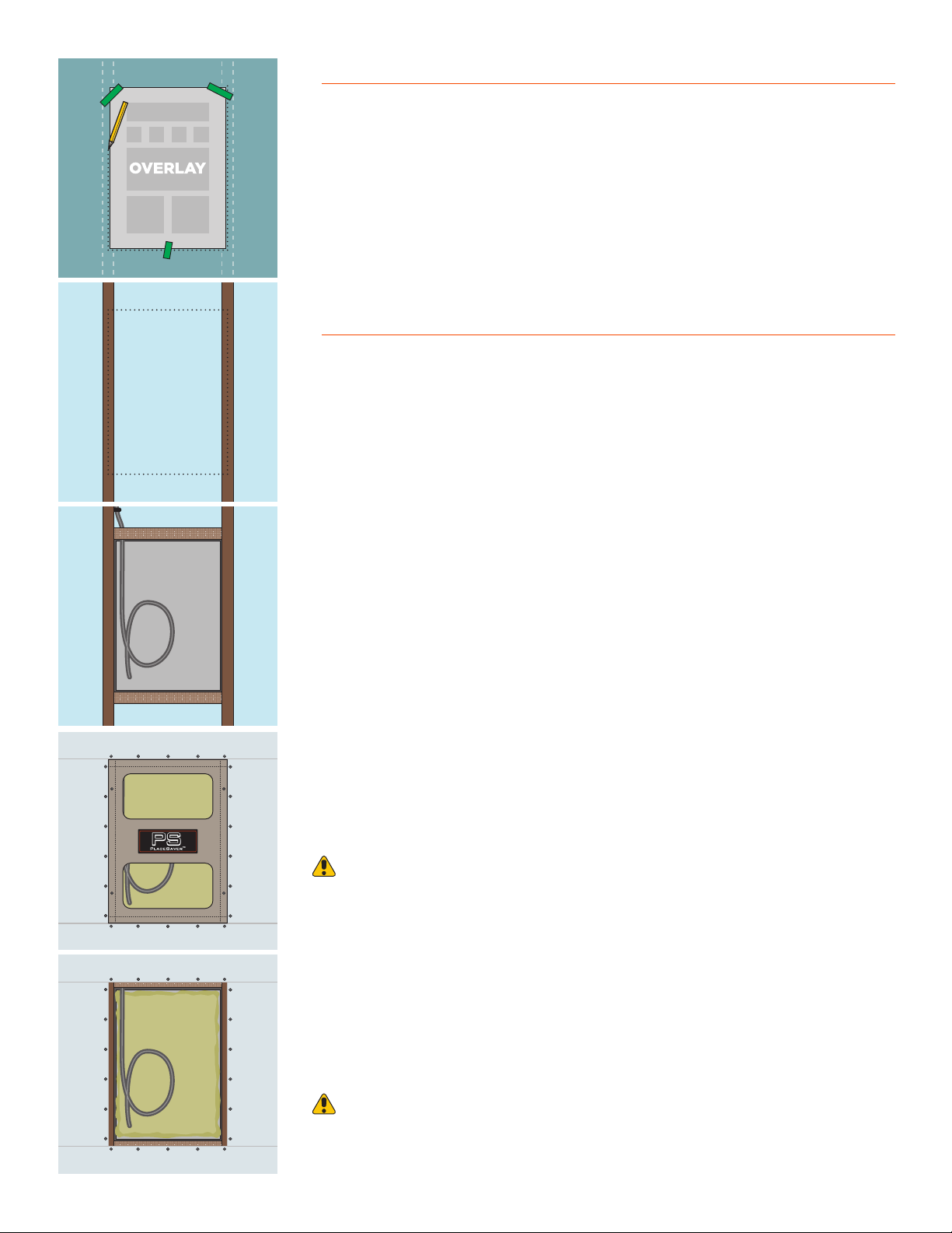
PLAN LOCATION
FRAMING
MBX & WIRE
PLACESAVER THEN DRYWALL
REMOVE PLACESAVER
16" OC

5. CONNECT SPEAKER WIRES
Insert the speaker wires into the binding posts on the speaker crossover (or
BX back box) noting proper polarity.
For smaller gauge wires, bend the exposed wire back upon itself prior to
insertion to make better contact with the binding posts.
6. SPEAKER MOUNTING
Attach the speaker panel screw flanges directly to the structural framing
using the provided wallboard screws. The panels have been pre‑drilled with
the proper number of holes. Be sure that all of the screws are installed and
that they hold securely to the framing.
Do not use nails.
7. RECHECK SPEAKER REGISTRATION
Now that the speaker is secured, recheck that the outer flange of the speaker
is flush with the surrounding wallboard.
Place a 4‑foot straight edge across middle of the speaker to verify that the
speaker face protrudes approximately 1/16" (2mm) beyond the wallboard in
each direction.
Check that the speaker is not warped from strain caused by uneven
framing. A warped speaker frame will cause the speaker face to bulge.
Having the correct registration minimizes the amount of joint compound that
might be built up over the face of the speaker during the finishing process.
This 1/16" (2mm) protrusion of the speaker face will become invisible after
the seams are properly finished and joint compound is feathered out from
the speaker appropriately.
Note: The typical installations shown above are provided as guidelines. For
your installation, the number and thickness of shims needed may dier due to
variances in wallboard material and other construction variables.
5/8” Wallboard
Structural
Framing
Speaker Frame
1/8” (4mm)
Shim
Speaker
Face
Screw
Flange
Joint
Compound
Seam
Tape
5/8” (16 MM) WALLBOARD
Install with screw flange flush to wallboard.
Speaker face to protrude by 1/16” (2mm) so
plaster can be feathered away from speaker.
1/2” Wallboard Speaker Frame
Structural
Framing
No Shims
Typically
Required
Speaker
Face
Screw
Flange
Joint
Compound
Seam
Tape
1/2” (13 MM) WALLBOARD
Install with screw flange flush to wallboard.
Speaker face to protrudes by 1/16” (2mm) so
plaster can be feathered away from speaker.
8. TEST SPEAKER SOUND
Before proceeding to wall finishing, test each speaker with music or pink
noise from an amplified sound source at listening volume to ensure full
speaker functionality.
Make note of sound coming from the high/mid/low frequency drivers of
each speaker and listen for any rattling or vibration.
Now is the time to correct any potential issues.
CHECK
REGISTRATION
SHIM IF NECESSARY
CONNECT WIRING
ATTACH SPEAKER
TEST WITH AMP
1/16"
(2mm)
GAP

WALL FINISHING
9. SEAM FINISHING
After the registration and sound check, seam finishing can proceed. The
speaker panel should be finished in place similar to any other piece of
wallboard.
Self‑adhesive nylon mesh tape is recommended due to its ease of use,
however paper tape is also acceptable.
Use only air-dry joint compounds and plasters for seam finishing. Do not
use chemically curing joint compound.
For best results, we recommend at least three light applications of joint
compound, sanding between coats.
Allow 24 hours between each application of joint compound for complete
drying. Failure to allow the joint compound to completely dry between
applications may result in fine hairline cracking around the speaker. If
this occurs, repair the crack using standard wall finishing techniques. The
crack will not reappear.
The joint compound should be spread beginning 2”‑3” in from the speaker
edge and then feathering outward 16”‑20” in order to achieve a smooth, flat
transition.
It is important that enough joint compound be applied around the speaker
to make a very gradual transition from the surface of the wallboard to the
face of the speaker panel. Every situation is dierent, but it will normally take
at least a 16”‑20” (30cm) fan of joint compound around the perimeter of the
panel to create a flat‑looking transition.
Be sure to feather the joint compound away from the speaker as to not build
up more than the maximum allowed 1/16" (2 mm) of joint compound over
the face of the speaker panel.
Stealth Acoustics speakers do not require a skim coat to attain a smooth
finish. However, some advanced finishing techniques and materials such as
Venetian plaster or heavy plaster coats may require skimming over the front
of the speaker. In these situations, it may be necessary to shim the speaker
proud of the surrounding wallboard so that we avoid build‑up of more than
1/16" (2 mm) in thickness on the face of the speaker.
10. SAND SMOOTH
Sanding is the last important step before the painting begins. This can make
or break the quality of the installation.
When sanding, imperfections in the application of the joint compound may
appear. If so, additional joint compound and sanding may be needed to
create a seamless transition.
Best practice may include the use of a flashlight to shine sheer light down
the wall or ceiling in order to identify high/low spots in the finish work.
11. PAINT AND FINISH
Once sanding is complete the face panel is ready for painting.
Light “orange peel” texture, light knock‑down texture, wallpaper, veneer, or
level 5 finish may be applied.
Heavy knock down or trowel finishes are not recommended. Stealth
Acoustics speaker face panels are engineered for optimum audio
performance with no more than 1/16” (2mm) of any material applied to
the surface of the speaker. To exceed the 1/16” (2mm) limitation will cause
degradation of audio quality.
StealthAcoustics.com
T 888.865.6800 | F 360.424.8872
A Division of Dimensional Communications, Inc.
1220 Anderson Road | Mount Vernon, WA 98274
SEAM TAPE
JOINT COMPOUND
SAND BETWEEN COATS
INSPECT FINISH WHEN DRY
PRIME & PAINT
©2021 Stealth Acoustics REV 21.04
This manual suits for next models
1
Table of contents


