Stealth Designer+ SC-09FM-HP230 User manual

UNIVERSAL FL R/CEILING
INSTALLATI N MANUAL
odels:
SC-09FM-HP230
SC-12FM-HP230
SC-18FM-HP230
SC-24FM-HP230

Safety Precautions . . . . . . . . . . . . . . . . . . . . . . . . . . . . . . . . . . . . . . . . . . . . 2
System Requirements . . . . . . . . . . . . . . . . . . . . . . . . . . . . . . . . . . . . . . . . . . 3
Suggested Tools . . . . . . . . . . . . . . . . . . . . . . . . . . . . . . . . . . . . . . . . . . . . . . 4
System Parts . . . . . . . . . . . . . . . . . . . . . . . . . . . . . . . . . . . . . . . . . . . . . . . . . 5
Installation Site Instructions . . . . . . . . . . . . . . . . . . . . . . . . . . . . . . . . . . . . . 6
Indoor Unit Installation . . . . . . . . . . . . . . . . . . . . . . . . . . . . . . . . . . . . . . 7-9
Piping Installation . . . . . . . . . . . . . . . . . . . . . . . . . . . . . . . . . . . . . . . . . 10-13
Power & Wiring . . . . . . . . . . . . . . . . . . . . . . . . . . . . . . . . . . . . . . . . . . . 14-16
Controller Installation and Setup . . . . . . . . . . . . . . . . . . . . . . . . . . . . . . . . 17
Testing and Inspection . . . . . . . . . . . . . . . . . . . . . . . . . . . . . . . . . . . . . . . . 18
Troubleshooting . . . . . . . . . . . . . . . . . . . . . . . . . . . . . . . . . . . . . . . . . . . . . 19
Diagnostic Codes . . . . . . . . . . . . . . . . . . . . . . . . . . . . . . . . . . . . . . . . . 20 -23
Installation Record . . . . . . . . . . . . . . . . . . . . . . . . . . . . . . . . . . . . . . . . . Back
Thank you for choosing a
Stealth
Universal Floor/Ceiling Ductless
Heat Pump System
Please read this installation manual carefully before installing and starting up
the Floor/Ceiling Ductless System. Take a moment to fill out the product and
installation form on the back cover. Retain both the manual and installation
record for future reference.
Table of Contents

SAFETY PRECAUTI NS
Please read the following before installation.
This is the safety alert symbol. It is used to alert you to potential
personal injury hazards. Obey all safety messages that follow this
symbol to avoid possible injury or death.
This mark indicates procedures which, if improperly performed,
might lead to the death or serious injury of the user.
This mark indicates procedures which, if improperly performed, might
possibly result in personal harm to the user, or damage to property.
Notice is used to address practices not related to personal injury.
General Safety Precautions
1. Instructions for installation and use of this product are provided by the manufacturer.
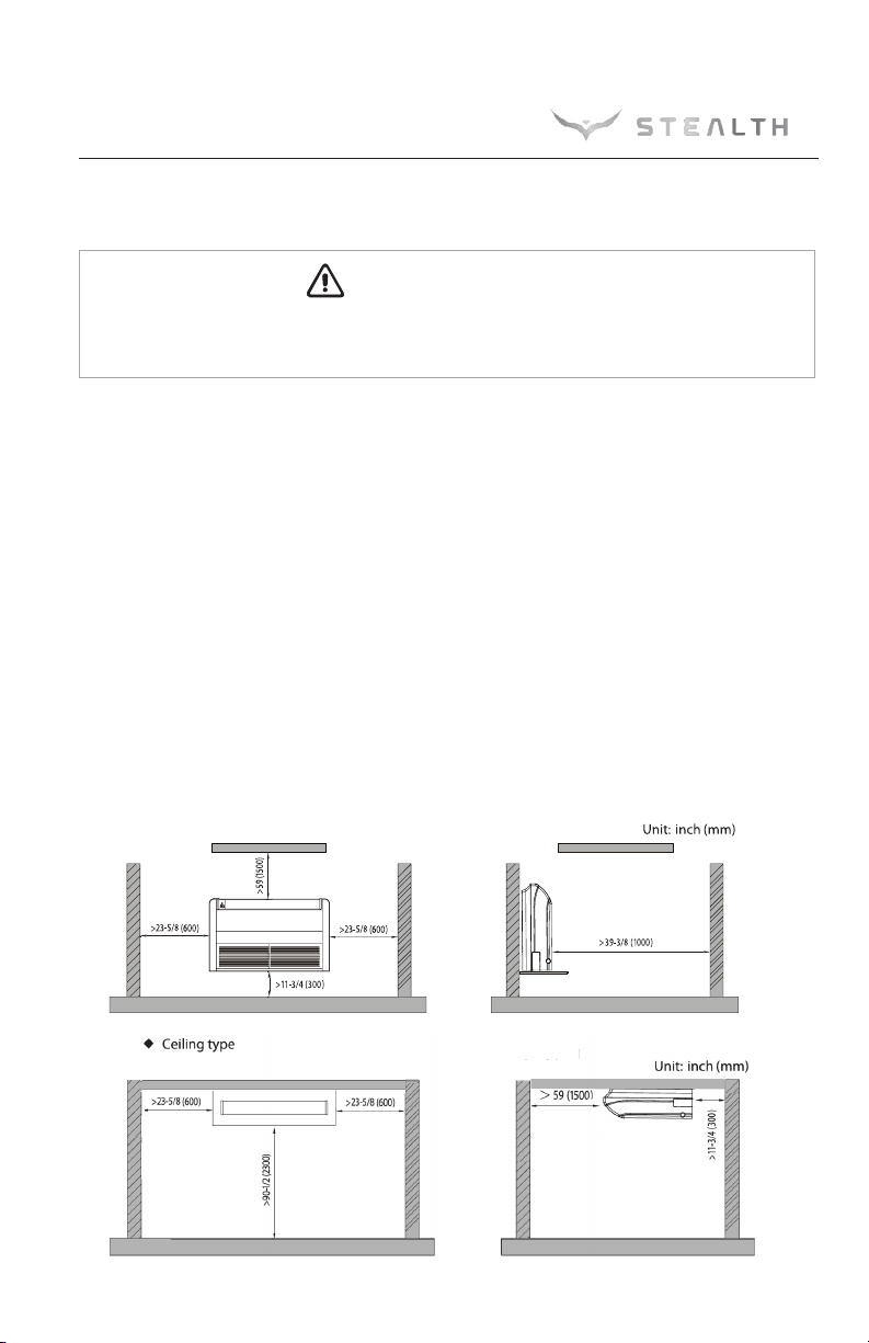
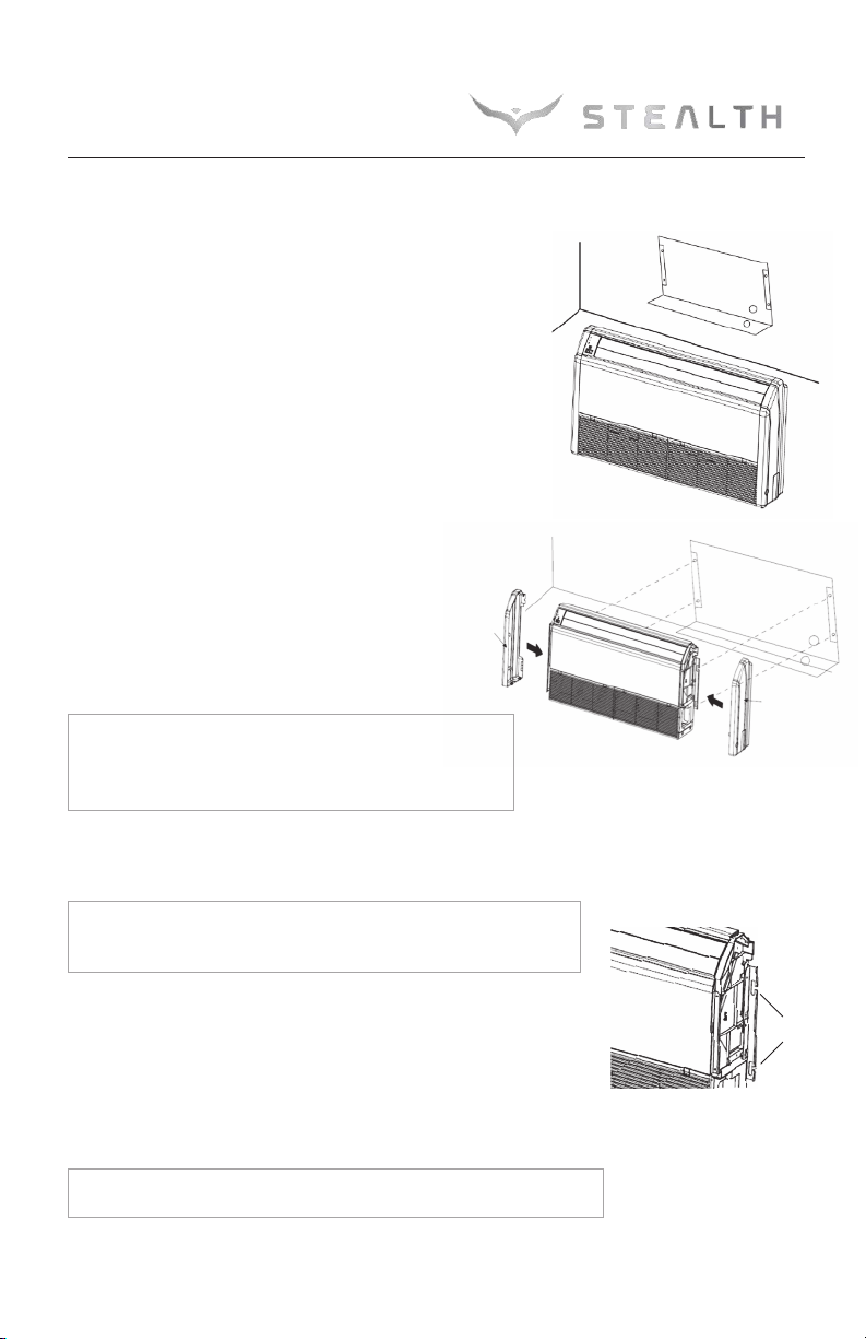
For proper operation, the system must be installed in accordance with this
installation manual.
2. Installation must be performed in accordance with local laws, regulations and
National Electrical Codes (NEC).
3. If there is a refrigerant leak while work is being carried out, ventilate the area.
Do not allow refrigerant to come in contact with a flame as it produces toxic gas.
4. Disconnect all electrical power to the indoor and outdoor units until the system is
ready for start-up and checkout.
5. When installing or repairing the system, use only R410A refrigerant. Do not
mix refrigerant with other gases. If air or other gas enter the refrigeration system,
the pressure inside the system may rise to an abnormally high value and cause
damage or injury.
This appliance is not intended for use by persons (including children) with reduced physical,
sensory or mental capabilities, or lack of experience and knowledge, unless they have been given
supervision or instruction concerning use of the appliance by a person responsible for their safety.
WARNING
CAUTION
NOTICE
WARNING
2

3
SYSTEM REQUIREMENTS
PIPE SIZE in (mm)
Condensate Drainage
It is recommended that condensate drainage systems use pipe either the same diameter
or larger (excluding the raising section) than that of the connecting pipe. The unit condensate
port is 0.67 in. (17mm) outside diameter.
Interconnecting Cable
The Floor/Ceiling unit is powered from the outdoor unit. Use recommended 14/4 AWG stranded
copper conductors THHN 600V unshielded wire.
Unit Size (BtuH)
9,000 1/4 (6) 3/8 (9.5) 88/110 lbs.
12,000 1/4 (6) 3/8 (9.5) 88/110 lbs.
18,000 1/4 (6) 1/2 (12) 88/110 lbs.
24,000 3/8 (9.5) 5/8 (16) 100/120 lbs.
Net/Gross Weight
Liquid Line Suction/Gas Line
N TE:
Insulate all condensate drain pipes to prevent sweating and possible water damage.
N TE:
Use shield cable if installation is in close proximity of RF and E I transmitting devices.

• Standard Wrench
• Adjustable/Crescent Wrench
• Torque Wrench
• Hex Keys or Allen Wrenches
• Drill & Drill Bits
• Hole Saw
• Pipe Cutter
• Screw drivers (Phillips & Flat blade)
• anifold and Gauges
• Level
• R410A Flaring Tool
• Clamp on Amp eter
• Vacuum Pump
• Safety Glasses
• Work Gloves
• Refrigerant Scale
• icron Gauge
SUGGESTED T LS
4

5
Air inlet
SYSTEM PARTS
Indoor Unit
Part Name
1.
Front Cabinet
2.
Air Inlet
3.
Wired Controller
(Optional)
4.
Remote Controller
5.
Drain Pipe
6.
Gas Pipe
7.
Liquid Pipe
8.
Service Cover
9.
Front Panel
utdoor Unit
Air outlet
Air inlet
9
8
3
4
1
2
76 5
The refrigerant pipe, drain pipe and electrical wiring for this unit should be installed by a
qualified HVAC professional only.
CAUTION
Air utlet
Power
Supply
XK-19

6
INSTALLATI N SITE INSTRUCTI NS
Indoor Unit
The unit must be installed in a location which can withstand four times the weight of the unit.
Inadequate support may result in serious property damage and injuries.
Select a site that allows for the following:
•Ensure the installation complies with the installation minimum dimensions and meets the
minimum and maximum connecting piping length and maximum change in elevation.
• Air inlet and outlet should be clear of obstructions, ensuring proper airflow throughout the room.
• Condensate can be easily and safely drained.
• All connections can be easily made to outdoor unit.
• Indoor unit is out of reach of children.
• A structure strong enough to withstand four (4) times the full weight of the unit.
• Filter can be easily accessed for cleaning.
• Leave enough free space to allow access for routine maintenance.
•
Do not install in a laundry room or by a swimming pool due to chemicals corroding indoor unit coil.
WARNING

7
IND R UNIT INSTALLATI N
Indoor Unit Dimensions
Model ABCDH
SC-09FM-HP230
48/1220 8.9/225 45.6/1158 11/280 27.6/700
48/1220 8.9/225 45.6/1158 11/280 27.6/700
48/1220 8.9/225 45.6/1158 11/280 27.6/700
48/1220 8.9/225 45.6/1158 11/280 27.6/700
IND R UNIT DIMENSI NS Inches (mm)
Preparing Indoor Unit for Installation
1. Remove the air inlet grille from the indoor unit to access screws that secure the side panels by
unhooking grille latches and removing screws.
2. Locate and remove the screw securing right side
panel. Remove right side panel from indoor unit by
sliding it up and off as shown in the figure right.
3. Repeat procedure to remove the left side panel
Begin the indoor unit installation by removing the air inlet grille and both side panels from unit as follows:
Remove the screw
Remove the screw
SC-12FM-HP230
SC-18FM-HP230
SC-24FM-HP230

8
1. Determine the mounting location on the wall for the indoor
unit. Follow the selection criteria in the previous section.
2. Locate the factory supplied installation template included
in carton and attach to the wall.
3. Verify the installation template is level right to left
and is a minimum 11 3/4 inches above the floor.
ark the 4 mounting holes for the indoor
unit. Also mark the condensate drain and
refrigeration pipe hole.
N TE:
Depending on the installation, the refrigeration
pipes and condensate drain hose may exit from the rear
or bottom of the unit.
4. Drill 4 mounting holes and insert anchor bolts (field supplied)
into drilled holes.
N TE:
It is recommended to install screw anchors for sheet rock,
concrete block, brick and such type of walls.
5. Verify indoor unit mounting by carefully lifting unit and setting it
on the 4 anchor bolts using the factory provided slots on the side
brackets as shown in figure right
6. Carefully remove indoor unit from anchor bolts in order to begin
making piping connections.
N TE:
Do not reinstall air inlet grille or side panels until instructed.
The Universal Floor/Ceiling units allow for wall or ceiling
mounting. Follow the instructions for the desire type of
installation.
Wall Mounting Installation
IND R UNIT INSTALLATI N
Laying ut Indoor Location
Mounting
Slots
Paper Template
Paper Template
Right Side
Panel
Left Side
Panel
Wall

9
IND R UNIT INSTALLATI N
Ceiling Mounting Installation
1. Determine the mounting location on the ceiling for the indoor
unit. Follow the selection criteria in the previous section.
2. Locate the factory supplied installation template included
in carton and attach to the ceiling.
3. ark and drill the 4 mounting holes for the indoor unit.
4. Depending on the type of ceiling, attach the threaded hanger
bolts securely to the support stud. Before lifting the indoor unit
to the installation location, insert the upper nuts, flat washers
(with insulation), flat washers (without insulation), lower nuts
and double locking nuts on the threaded hanger bolts.
N TE:
The hanger bolts, nuts, and washers are field
supplied. Install the washer with cushion so that the insulation
faces downward.
5. Verify indoor unit mounting by carefully lifting unit and
setting it on the 4 hanger bolts (between the two washers)
using the factory provided slots on the side brackets as
shown in figures right.
6. Confirm that the indoor unit main body is level horizontally as
shown in figure bottom right. Adjust mounting nuts as needed.
7. After checking the positioning of the indoor unit, securely tighten
the hanger nuts to fasten the indoor unit in place.
N TE: Do not reinstall air inlet grille or side panels
until instructed.
Mounting
Slots
Level Bar
Hanging Bolt
Threaded
Hanger Bolt
Washer
Nut
Nut
Nut
Washer
Nut Flat Washer
Flat Washer
Nut
Paper Template

Piping Preparation
1. Do not open service valves or remove protective caps on pipes until instructed by this manual.
2. Keep tubing free of dirt, sand, moisture and contaminants.
3. Insulate each refrigerant pipe and condensate hose with minimum 3/8” (10 mm) wall
thermal pipe insulation.
4. Bind refrigerant pipes and communication cable together with cable ties at 12-inch intervals.
5. Include the condensate hose in bundle for exterior portion only.
10
PIPING INSTALLATI N
Refrigerant Piping
Drill Hole in Wall
1.
Locate and mark proper location for the wall hole.
2.
Cut the wall hole with a 5° to 10° downward
slant to the outdoors. See Wall Hole Size table.
3. Insert a wall sleeve (field supplied) into hole to
to prevent damage to refrigerant pipes, insulation,
condensate drain hose and wiring.
4. Proper weather proofing of the wall surface and
wall sleeve is essential to assure a trouble-free
installation. Apply sealant, caulking or equivalent
weather proofing material around the perimeter of
the wall sleeve (interior & exterior) to eliminate
outdoor air and water leaks into the indoor space.
N TE: Expandable foam insulation may be added to fill large wall gaps.
Apply per manufacturer's instructions.
Seal Hole
Hole Size
Indoor Outdoor
Wall Hole Diagram
Oil return bend
Indoor
Outdoor
20 ft.
30 ft.
Oil return bend
Indoor Unit below utdoor Unit Application
When height difference between indoor unit and outdoor
unit is more than 30 feet, an oil return bend should be added
for every 20 feet of connection pipe as shown.
Wall
Hole Sleeve
Unit Size Wall Hole Size
(BtuH) Dia
-
inch (mm)
9,000 2 1/4 (55)
12,000 2 1/4 (55)
18,000 2 3/4 (70)
24,000 2 3/4 (70)

11
PIPING INSTALLATI N
Indoor Unit Pipe Connections
1. Feed refrigerant pipes, drain hose and communication cable assembly through wall hole
from outdoor to the Floor/Ceiling indoor unit.
2. Pull the piping assembly to the indoor unit. Carefully bend refrigerant pipes to meet indoor
unit connection ports. Use proper tools to avoid kinks.
3. Add a small amount of refrigerant oil to
both ends of the flare fittings.
4. Starting with either refrigerant pipe, carefully
center the pipe to the indoor unit connection
port then hand tighten the flare nut.
5. Repeat procedure with remaining pipe.
6. Tighten both flare nuts using a standard wrench and a torque wrench as shown below.
7. Carefully tighten flare nuts to correct torque level referring to the Torque Table below.
8. Individually insulate each bare refrigerant pipe and joint as shown below to prevent sweating.
Pipe Diameter Nut Size Tightening Torque
inch (mm) inch (mm) ft-lbs N-m
1/4 (6) 1/4 (17) 11 to 22 15 to 30
3/8 (9.5) 3/8 (22) 26 to 29 35 to 40
1/2 (12.7) 1/2 (25) 33 to 37 45 to 50
5/8 (16) 5/8 (29) 44 to 48 60 to 65
Liquid pipe
Gas pipe
Front outlet
Insulate pipe connection
Insulate pipe
Insulate pipe
2
Reference A:
R
Cover this portion with insulation
Pipe insulation
L
Over tightening may damage flare connections and cause leaks.
CAUTION
Copper
piping
Oil applied
(to reduce friction
with the flare nut)
Flare nut Oil applied
(improves seal
air-tightness)
90
90
Holding spanner
Torque wrench
Floor/Ceiling Indoor Unit

Indoor Condensate Drain Piping
PIPING INSTALLATI N
12
Observe all local sanitary codes when installing condensate drains.
WARNING
The drain piping should be as short as possible with a constant downward slope. It is recommended
to install the condensate drain system with hard polyvinyl chloride (PVC) pipe and matching
connectors. Use piping of the same or greater diameter as the unit connection.
The Floor/Ceiling drainage port diameter is 11/16-in
(17-mm) OD.
Pitch the condensate drain pipe at a gradual 2.5% pitch
(Example: ¼-in drop over a 10-in length) without
obstructions. Use pipe hanger/brackets to support
the condensate drain pipe from dropping.
If a gradual pitch from the drainage port is not obtainable, use an auxiliary condensate pump with
float valve. A float valve is recommended to shut off the system if auxiliary pump fails.
N TE: Insulate condensate hose and/or pipes to prevent sweating which may cause
water stains or wall damage.
Ceiling
H
Hangers
Wall
Typical Drainage System
utdoor Unit Pipe Connections
Carefully bend and adjust length of refrigerant pipes to meet
outdoor unit port connections. See installation instructions
shipped with the outdoor unit for further instructions..

PIPING INSTALLATI N
Indoor Condensate Drain Piping (con’t)
Completing Condensate Drainage Piping
• Include the exterior section of condensate hose in the pipe/wire bundle.
• Fasten the refrigerant and condensate pipe assembly to the exterior
wall for support.
• The drain pipe should terminate 6 inches above grade.
Test the Condensate Drainage Piping
• Find the drainage port with the air inlet grille and right side panel removed.
• Slowly add 20 to 24 oz. of water to the drain pan as shown below.
• Water must drain freely from the unit If not, check the pipe slope or see if there are any pipe restrictions.
• Verify all piping joints are leak free.
13

P WER AND WIRING INSTALLATI N
WARNING
1. Before obtaining access to wire terminals, all electrical supply circuits must be
disconnected, locked out and tagged.
2. Always use an independent (dedicated) circuit and provide an independent (dedicated)
circuit breaker to supply power to the system.
3. Use a circuit breaker with adequate capacity to meet the requirements of the total system.
4. All circuit breakers or fuses for the indoor and outdoor units should be installed per the
National Electric Code (NEC) and local regulations.
5. Electrical wiring must be completed in accordance with NEC, local laws, and regulations
of the electric company so that the system will operate properly.
6. Provide a GFI circuit breaker at the electrical panel in accordance with the NEC and the
local electrical company standards.
7. Connect the power supply firmly to the terminal block. Improper installation may
cause a fire.
CAUTION
1. The main power supplies are high-voltage, while the communication wire and the Tether
Controller are low-voltage. They should be installed separately to avoid electromagnetic
interference.
2. High-voltage and low-voltage lines should pass through separate rubber rings at electric
box covers.
3. If the indoor unit communication wire (to the outdoor unit) and power wire are connected
incorrectly, the air conditioner may be damaged.
4.
Ground both indoor unit and outdoor unit to earth ground in accordance with the applicable
local and national codes.
14

15
P WER AND WIRING INSTALLATI N
Electrical Connections to Floor Ceiling
Disconnect all electrical power to indoor and outdoor units including disconnects,
fuses and circuit breakers. Lockout and tag all disconnect switches.
Electric Wiring Between Indoor Unit and utdoor Unit
G
Power:
Wired Tether
Controller
XK-19
NN
(
N
(
1N
(
1
)
N
(
1
)
22
33
CN1CN1
22
33
NN
(
N
(
1N
(
1
)
N
(
1
)
CN9
N
(
1
)
CN9
Cassette Unit
Typical Wiring Diagram
1. Adjust the length of the interconnecting wires so that it can easily reach the Floor Ceiling
electrical control box.
2. Open electrical control box cover and route the interconnecting wires to field wiring terminal block.
N TE:
The indoor unit is powered from the outdoor unit, depending on local code, a
disconnect switch may need to be installed to a power supply circuit.
3. Secure interconnecting wires to the terminal block
as shown in the connection diagram at right:
N TE:
Record wire colors and terminal references
for uses with Outdoor Unit wire connections.
4. Secure all wires inside wire clamp/strain relief. Verify wires
are secure, not loose and no external force on wires affects the connections at the terminals.
N TE:
Crossing interconnecting wires will cause system malfunction and possible damage.
5. Replace field wiring cover on unit.
WARNING
utdoor Electrical Wiring
For Outdoor Unit wire connections, see installation instructions shipped with the outdoor unit.
Red
White
Floor/Ceiling
Unit
Black
Green

16
P WER AND WIRING INSTALLATI N
Installing Wired Tether Controller to Floor/Ceiling Unit
1. Open decorative grille and locate 4 pin connector for wired controller on Floor/Ceiling
main body.
2. Route wired controller wires to 4-pin connector and connect Tether Controller to
Floor/Ceiling.
N TE:
Use the supplied cable, with OE plugs on either end. Do not cut or splice.
Conceal any excess cable.
1. Replace decorative grille being careful not to pinch wires.
2. Remove back plate from Wired Controller.
Outdoor Unit
Indoor Unit
Indoor Unit Disconnect Switch
Wires
Outdoor Unit
Local codes may require a disconnect switch within sight of the indoor unit. Use a DFS Disconnect
Switch Accessory Kit (Part No: DFS-SWITCH-A) to break interconnecting wires going to the N(1),
2, 3, terminals on the indoor unit, as shown in the wiring diagram below:
Indoor Disconnect Switch ( ptional)
White
Black
Green
Red

17
C NTR LLER INSTALLATI N AND SETUP ( ptional)
The following is a brief overview of the Wired Tether Controller installation. See Tether Controller
Owner's anual for more detailed instructions for setup and operation.
Preparation for Installation
Select a proper location on the wall for mounting the Tether
Controller. Install switch box, if required by code. The maximum
wire length between indoor and Tether Controller is 26 ft (8m).
Run communication cable (as desired) between indoor unit
and selected wall mounting location. See Indoor Unit wiring
section for instruction to connect the Wired Tether Controller
to the indoor unit.
Wired Tether Controller Installation
Pull communication cable through switch box (if one
is used) and Wired Tether Controller backplate. Securely
fasten backplate to the switch box or wall.
Locate wire terminals connector on rear of Tether
Controller panel. Carefully connect wire to controller
connector. Verify connector is secure, not loose and
no external force on wires affects the connections at
the terminals. Push extra cable into wall and secure
controller panel to backplate mounted on the wall.
N TE: Do not cut or splice communication cable.

Start-up Checklist
□Turn on main power to indoor and outdoor units.
•
Verify the system is not displaying an error code on the indoor unit display.
□Point the Remote Controller at the
Floor/Ceiling unit and Press the n button.
• Verify the remote controller display turns ON
and the Power Indicator lights up on the
Floor/Ceiling unit.
□Press the Mode button to Cooling.
Adjust the room setpoint to bring the system on in cooling mode. The system should start
cooling mode within 3-5 minutes.
• Verify the setpoint lights up on the Floor/Ceiling unit display.
• Verify the outdoor fan and compressor are operating.
• Verify the indoor fan is operating.
• Verify the indoor discharge air is cooling the room.
□Press the Mode button to Heating.
Adjust the room setpoint to bring the system on in heating mode. The system should start
heating mode within 3-5 minutes.
• Verify the new setpoint lights up on the Floor/Ceiling unit display.
• Verify the outdoor fan and compressor are operating.
• Verify the indoor fan is operating.
• Verify the indoor discharge air is heating the room.
□Press the FF button on the Remote Controller.
• Verify Remote Controller display turns OFF and the system shuts OFF.
verview of Display Panel
1. Power Indicator: Power indicator will be on after electrical power
is turned on, while it will be off after disconnecting power.
2. COOL Indicator: COOL indicator will be on after COOLmode is
activated while it will be off after COOL mode is turned off.
3. Heat Indicator: HEAT indicator will be on after HEAT mode is
activated, while it will be off after HEAT mode is turned off.
4. Indoor setpoint and temperature display.
TESTING AND INSPECTI N
1
2
3
4
18

TR UBLESH TING
PR BLEM
System does not restart.
Indoor unit emits unpleasant odor
when started
You hear a“water flowing”sound.
A thin fog or vapor coming out
of the discharge register when
system is running.
You hear a slight cracking sound
when the system stops or starts.
The system will not run.
The unit is not heating or cooling
adequately.
Water leaking from the indoor
unit into the room.
The unit will not deliver air.
CAUSE/S LUTI N
Cause: The system has a built-in three-minute delay to prevent short and/or rapid cycling of
the compressor.
Solution: Wait three minutes for the protection delay to expire.
Cause: Typically unpleasant odors are the result of mold or mildew forming on the coil surfaces
or the air filter.
Solution: Wash indoor air filter in warm water with mild cleaner. If odors persist, contact a
qualified service professional to clean the coil surfaces.
Cause: It is normal for the system to make“water flowing”or“gurgling”sounds from
refrigerant pressures equalizing when the compressor starts and stops
Solution: The noises should discontinue as the refrigerant system equalizes after two or three minutes.
Cause: It is normal for the system to emit a slight fog or water vapor when cooling extremely humid
warm air.
Solution: The fog or water vapor will disappear as the system cools and dehumidifies the room space.
Cause: It is normal for the system to make “slight cracking” sounds from parts expanding and
contracting during system starts and stops.
Solution: The noises will discontinue as temperature equalizes after two or three minutes.
Cause: There are a number of situations that will prevent the system from running.
Solution: Check for the following:
• Circuit breaker is “tripped” or “turned off.”
• Power button of controller is not turned on.
• Controller is in sleep mode or timer mode.
• Otherwise, contact a qualified service professional for assistance.
Cause: There are a number of reasons for inadequate cooling or heating.
Solution: Check the following:
• Remove obstructions blocking airflow into the room.
• Clean dirty or blocked air filter that is restricting airflow into the system.
• Seal around door or windows to prevent air infiltration into the room.
• Relocate or remove heat sources from the room.
Cause: While it is normal for the system to generate condensate water in cooling mode,
it is designed to drain this water via a condensate drain system
to a safe location.
Solution: If water is leaking into the room, it may indicate one of the following.
• The indoor unit is not level right to left. Level indoor unit.
• The condensate drain pipe is restricted or plugged. All restrictions must be removed
to allow continuous drainage by gravity.
• If problem persists, contact a qualified service professional for assistance.
Cause: There are a number of system functions that will prevent air flow.
Solution: Check for the following:
• In heating mode, the indoor fan may not start for three minutes if the room
temperature is very low. This is to prevent blowing cold air.
• In heat mode, if the outdoor temperature is low and humidity is high, the system
may need to defrost for up to 10 minutes before beginning a heating cycle.
• In dry mode, the indoor fan may stop for up to three minutes during the compressor off delay.
• Otherwise, you should contact a qualified service professional for assistance.
19
This manual suits for next models
3
Table of contents