9. Fuel Injectors
10. Alternators
11. Water Pumps
12. Smog Pumps
13. Power Steering Pumps
14. AC Compressors
15. Industrial Equipment
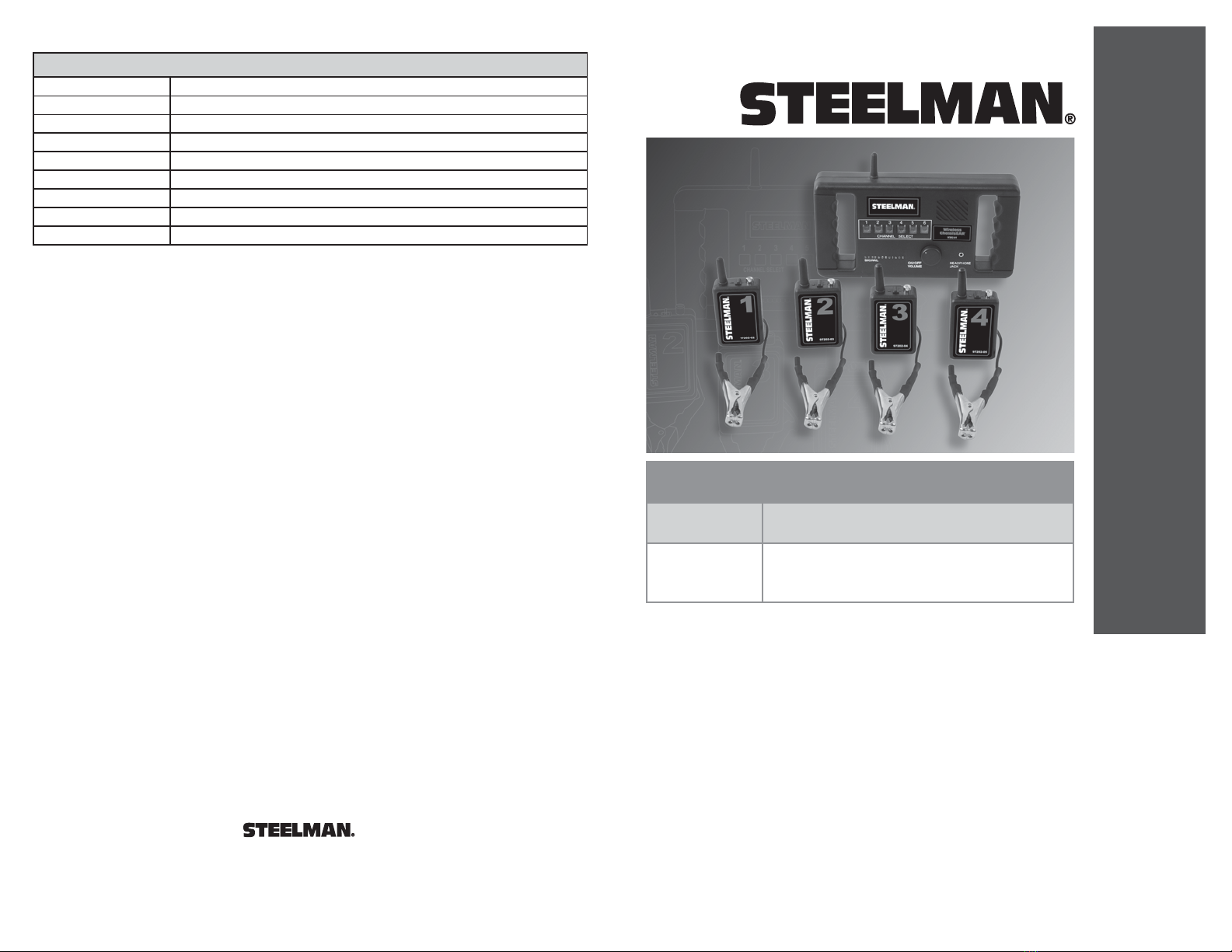
97202 - Wireless ChassisEAR®- STEELMAN
INSTRUCTION MANUAL
21
JS Products, Inc. • 5440 S. Procyon Ave. • Las Vegas, NV 89118
Phone: 702-362-7011 • Fax: 775-898-8773 • www.steelmantools.com
Printed in China
Rev: 03/07/09
LIMITED WARRANTY
STEELMAN
®JS Products, Inc. has carefully examined each product at the time of
manufacturing and warrants workmanship at the time of shipment. This warranty applies only
to the original consumer/purchaser and is not valid if the product is misused, or if accidental
damages occur.
STEELMAN
®JS Products, Inc. assumes no direct or indirect liability for
incidental or consequential damages resulting from the use of its products. This warranty
commences on the date of the original consumer purchase, and extends for 90 Days
thereafter.
In the event of a defect or malfunction of a product, wherein repair or replacement should be
necessary, call the Customer Service Department at 1-800-255-7011 for complete
instructions on how to return the product for warranty repair or replacement. The original
consumer/purchaser must provide a copy of the Bill of Sale or Invoice showing the date on
which the purchase was made. After the (ninety) 90 Day Period,
STEELMAN
®JS Products,
Inc. will charge a service charge for all parts and labor. Inbound and outbound freight will be
paid by the consumer/purchaser.
Some states do not allow limitations on how long an implied warranty lasts, so the above
limitation may not apply to you. Additionally, some states do not allow the exclusion or
limitation of incidental or consequential damages, so the above limitation may not apply
to you.
This warranty gives specific legal rights, and there may be other rights which vary from state
to state.
HOW TO USE
1) With the vehicle elevated, attach the clamps to the suspect areas. If, for example, you
suspect there is a bad wheel bearing, attach the clamps, one each, per wheel bearing. Put
the clamp on the tie rod or knuckle close to the inside of the wheel. In order to generate an
exact cross-comparison of sounds, place the clamp on identical opposite locations. With the
availability of two more channels, you could place transmitters on the transmission and
differential, since many times what you think is a wheel bearing turns out to be something
different. Or, if you suspect a brake problem, attach the 4 clamps adjacent to the brakes. The
closer the clamp is positioned to the suspected problem, the better sound reproduction you
will get.
2) Be sure the transmitters are securely fastened to the locations chosen.
Each Transmitter has 3 methods of attachment:
a) First, there are two internal magnets so that the transmitter can
hold to a metal surface.
b) Second, there is a velcro strap that can be wrapped around
any non-moving part.
c) Third, there is a spring-loaded clamp that can grab onto non-moving parts.
Be sure each transmitter is securely held in place with one of these methods to avoid
loss of transmitter from excessive bumps or shaking during road test.
Also, carefully check for clearance of all vehicle parts that are located close to the
transmitters to avoid contact/damage from movement or heat.
3) Using the location identifier note pad, record information on note pad of the location
and
corresponding channel for each mircrophone/clamp. This will allow you to properly assign the
problem noise to the proper malfunctioning part while conducting the road test.
4) It is highly recommended that if earphones are used during diagnoses (there is a
earphone jack available on the receiver), that there be a separate driver for the vehicle.
CAUTION:
It is against many state laws to operate a motor vehicle while wearing earphones.
5) Before conducting the road test, turn on the on/off-volume control switch located on the
front of the Wireless ChassisEAR®receiver. Select the first channel and adjust the volume
to the desired level. Various volume levels may reveal different sounds and problems.
Initially make a mental note of the sounds you hear as you listen. Next, push each channel
according to the location and make notes accordingly. You may make instant cross
comparisons of two locations, for example, channels #2 and #4, just by pushing the channel
indicators in an alternating manner.
IMPORTANT:
Make notes while driving (being cautious) as to what is heard on each channel (rattles,
squeaks, grinding, whining, etc.). When you have returned to the shop, you can then zero in
on the exact location of the noise/problem.
FUEL INJECTORS:
It is quick and easy to hook up the Wireless ChassisEAR®clamps on the fuel injectors.
The "tapping" solenoids are easily heard. If a clear metal-to-metal "ringing" sound is heard,
then the injector is clean. If the "needle" inside the solenoid is making a dull "thud", then a
deposit buildup more than likely exists inside the injector. A cleaning of the injectors is
suggested. It is important to listen to the injectors before and after cleaning in case one is still
dirty after cleaning.
NOTE:
This equipment has been tested and found to comply with the limits for a Class B digital
device, pursuant to part 15 of the FCC Rules. These limits are designed to provide reasonable
protection against harmful interference in a residential installation. This equipment generates,
uses and can radiate radio frequency energy and, if not installed and used in accordance with the
instructions, may cause harmful interference to radio communications. However, there is no
guarantee that interference will not occur in a particular installation. If this equipment does cause
harmful interference to radio or television reception, which can be determined by turning the
equipment off and on, the user is encouraged to try to correct the interference by one or more of
the following measures:
- Reorient or relocate the receiving antenna.
- Increase the separation between the equipment and receiver.
- Connect the equipment into an outlet on a circuit different from that to
which the receiver is connected.
- Consult the dealer or an experienced Radio/TV Technician for help.
FCC INFORMATION - CLASS "B" DEVICE
NOTE:
Changes or modifications to this equipment not expressly approved by
STEELMAN®
could void the user's authority to operate this equipment.
NOTE:
Only Cable Leads/Clamps supplied with this equipment must be used. It is the responsibility
of the user to use only the accessories supplied with this equipment.
STEELMAN
®
Wireless ChassisEAR®is a versatile electronic listening tool which is
designed to allow the user to listen to amplified sounds through a speaker or earphones
DURING a road test.
Some of these vehicle parts/areas include:
1. Wheel Bearings
2. Brake Calipers
3. C.V. Joints
4. Leaf and Coil Springs
5. Differentials
6. Transmissions
7. Body Squeaks and Rattles
8. Under the Dash
During a road test under load, these parts make different sounds than when the car is on a
hoist. In order to accurately diagnose an under car problem, the car must be driven during
diagnoses so that all parts and bearings are under full load and actual driving conditions.
Before using the Wireless ChassisEAR
®
for the first time, please review the components.
There are up to 6 extremely sensitive microphones/clamps that can be attached adjacent to
many difficult to diagnose vehicle parts. (see under "How to Use")
QTYQTYDescription Description
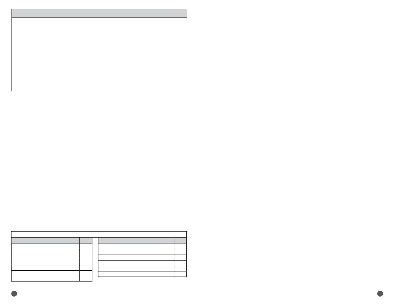
KIT CONTENTS
Receiver Unit (Rx)
Transmitter Units (Tx) - Channels 1-4
(Channels 5-6 optional - not shipped with kit)
Cable Leads / Clamps - For all Channels
Earphones
Velcro Straps
Nylon Straps
1
4
4
1
12
12
AAABatteries (Tx) 4 per Unit
AA Batteries (Rx) 6 per Unit
Blow Molded Case
Vinyl Pouch
Location Identifier Note Pad (25 sheets per pad)
Instruction Manual / Warranty Card
16
6
1
1
1
1
SPECIFICATIONS
97202
PART NO DESCRIPTION
CAUTION:
It is against many state laws to operate a motor vehicle while wearing earphones.
OPERATING INFORMATION
WARNING INFORMATION
Wireless ChassisEAR®
Wireless ChassisEAR®
Electronic Squeak and Rattle Finder
97202
97202-01
97202-02
97202-03
97202-04
97202-05
97202-06
97202-07
97202-08
Wireless ChassisEAR®Kit
WCE Receiver Box (Rx)
WCE Transmitter - Channel #1
WCE Transmitter - Channel #2
WCE Transmitter - Channel #3
WCE Transmitter - Channel #4
WCE Transmitter - Channel #5 (optional - not shipped with initial kit)
WCE Transmitter - Channel #6 (optional - not shipped with initial kit)
Cable Leads / Clamps - All Channels
CAUTION: When removing cable leads from transmitters, do not pull the wire or the warranty may
be voided. You may damage the connection in the transmitter. Instead, hold onto the
transmitter housing when removing cable lead.
REPLACEMENT PARTS
1 COLOR
BLACK =
0% Cyan
0% Magenta
0% Yellow
100% Black
Material: 28lb Bright White Gloss Text
Size: 5.5" W x 8.5" H Folded Size