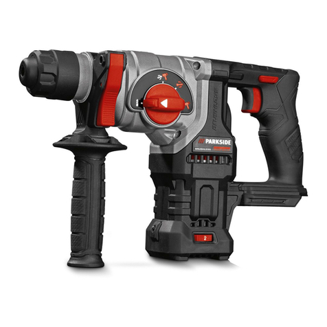
Stel 100001 Operating instructions

Battery Rail Drill
User and Maintenance Guide
Part No. 100001
Specialised Tools and Equipment Ltd,
Units 15, Riverside Court, Don road,
Sheffield, S9 2TJ
T0114 383 0110
F0114 383 0160
Einfo@specialisedtools.co.uk
Wwww.specialisedtools.co.uk

CONTENTS
1. Issue changes................................................................................................................... 3
2. Intended use.................................................................................................................... 3
3. Safety............................................................................................................................... 4
4. Technical specification..................................................................................................... 5
4.1. Drill Nomenclature .......................................................................................................... 5
4.2. Drill Specification............................................................................................................. 6
4.3. Hole cutting capabilities .................................................................................................. 6
4.4. Compliance...................................................................................................................... 6
4.5. Storage............................................................................................................................. 6
4.6. Transporting/shipping ..................................................................................................... 6
5. Operating instructions..................................................................................................... 7
5.1. Pre-use............................................................................................................................. 7
5.2. Fitting a Broaching Cutter................................................................................................ 7
5.3. Fitting Rail Shoe templates.............................................................................................. 8
5.4. Coolant System................................................................................................................ 8
5.5. Depressurizing the coolant bottle ................................................................................... 9
5.6. Using the Indexing Plate.................................................................................................. 9
5.7. Using the Over Rail Clamp ............................................................................................. 10
5.8. Drilling a Hole ................................................................................................................ 11
5.9. Do’s and Don’ts when using the BRDM18-FUEL Rail Drill. ............................................ 11
6. Routine maintenance .................................................................................................... 12
6.1. Slide Adjustment............................................................................................................ 12
6.2. Changing the Battery.................................................................................................... 12
6.3. Looking after your batteries .......................................................................................... 13
6.4. Rack and slide lubrication.............................................................................................. 13
6.5. Fixings ............................................................................................................................ 13
6.6. Labels and warning Instructions.................................................................................... 13
6.7. Routine maintenance schedule..................................................................................... 13
7. Technical Drawings........................................................................................................ 14
7.1. BRDM18-FUEL Main Assembly Parts List....................................................................... 14
7.2. BRDM18-FUEL Clamp Assembly (Pt No BRDM18-FUEL Clamp) .................................... 15
8. Service Parts .................................................................................................................. 18
9. Training.......................................................................................................................... 18
10. Service, test and repair.................................................................................................. 18
Note that this Manual from Specialised Tools and Equipment Limited (STEL) is intended as guideline only. STEL
accepts no liability in relation to the use or reliance of any information in this Manual.
All information in this Manual is based on the latest information available at the time of publication. STEL reserve
the right to make changes at any time without notice.
Owners and operators shall be responsible for ensuring that the relevant safe systems of work are in place.
STEL™ is a trademark of Specialised Tools and Equipment Ltd.
©2011 STEL.

Specialised Tools and Equipment Ltd 3
1. ISSUE CHANGES
Issue
Changes made
Date
Pages
changed
Changed by
1
New Issue
23.04.13
MJK
2
Complete change
12.01.2018
MJK
3
Service Parts added
09.04.18
Sec 8
included
CDM
4
Clamp & spare parts list amended
04-09-18
Various
CDM
2. INTENDED USE
Specialised Tools and Equipment Ltd has developed the industry’s first genuinely portable,
versatile and incredibly light weight rail drill weighing in at just 17kg!.
The STEL BRDM18-FUEL Rail drill is designed to drill fishplate or bonding holes to facilitate track
maintenance. The drill can be used with readily available templates for setting hole heights and
pitch. All other custom sizes to suit rail designations and hole positions are available upon
request.
A range of accessories and tools is available e.g. drilling templates, carry case, magnetic swarf
wand etc. Please contact STEL for further information.

Specialised Tools and Equipment Ltd 4
3. SAFETY
To ensure that the BRDM18-FUEL Drill is operated correctly, and any risks minimised to the
operator, the following should be observed:
In addition to any PPE equipment required by local regulations, as a
minimum, safety footwear, gloves and glasses must be worn when using
and drill.
Only trained and competent people can use the drill.
Do not use the drill if it is damaged, or if any parts are missing.
Do not use the drill on live 3rd or 4th rail electrified lines.
Do not exceed the limitations specified in the Technical Specification, or use
the drill for purposes other than those defined in the Intended Use.
Do not attempt to replace a cutter whilst a battery is fitted to the motor.
Do not wear loose clothing when using the drill.
Maintenance must be undertaken by competent personnel only.
Ensure that the templates fitted are the ones to suit the rail being drilled.

Specialised Tools and Equipment Ltd 5
4. TECHNICAL SPECIFICATION
4.1. Drill Nomenclature
Cutter feed handle
Clamping handle
Battery
holder pos’n
Quick
Release
Arbor
Coolant feed inlet
Rail shoe
template
On/off switch

Specialised Tools and Equipment Ltd 6
4.2. Drill Specification
•Weight: 17kg
•Dimensions: H = 370
W = 120
L = 470
•Voltage: 18v
•No load speed: 400/690 rpm
•Hand Arm Vibration reading: <2.5m/s2
•Sound pressure level: 88dB(A) at 380 and 101dB(A) at 680
•Max. drilling capacity: Ø32mm core drill, Ø13mm solid drill bit
4.3. Hole cutting capabilities
The following is a guideline based upon the use of a new cutter in each case and the amount of charge held by the
battery is also a governing factor.
Cutter Details
Number of holes (per battery)
Annular Broach cutter
Ø32mm (1 ¼”)
11
Ø22mm (1 1/8”
25
Solid drill bit
Ø13mm (1/2”)
13
Ø9mm (3/8”)
30
Ø5.6mm (7/32”)
42
Note: All values are per battery. Each drill is supplied with 2 batteries. Charging time per 9Ah battery approximately
120mins.
4.4. Compliance
In accordance with the following Directive(s):-
Machinery Directive 2006/42/EC, EN 61029, EN60745,
Directive 93/68/EEC CE Marking, EMC Directive 2006/95/EC
RIS170-PLT
4.5. Storage
Ensure that the drill is placed in its storage case immediately after use. Place all of the
templates and other ancillaries in the case after use. Ensure that the case and its contents
are stored in a dry clean environment.
4.6. Transporting/shipping
Ensure that the drill is transported in its storage case.

Specialised Tools and Equipment Ltd 7
5. OPERATING INSTRUCTIONS
To ensure correct and safe operation, the described sequence should be followed prior to use:
5.1. Pre-use
1. Prior to arriving at the worksite, ensure that all the batteries have full charge.
2. Check that the correct cutters and ejection pins are available and in good condition.
3. Check the correct templates are fitted or are available.
4. Check that there is sufficient coolant available to complete the job.
5.2. Fitting a Broaching Cutter
Prior to fitting or changing a cutter –ALWAYS remove the battery,
failure to do so could result in serious injury.
•Disconnect the battery from the drill.
•Insert the pilot pin in the broaching cutter. The main function of the pilot
pin is to ensure ejection of the slug at the end of each drilling cycle.
•Retract the motor slide using the cutter feed handle to provide more
space to fit the cutter.
•Twist the body of the arbor and insert the cutter into it. Align the flats
of the cutter with alignment marks on the arbor body.
•Insert the cutter firmly into the arbor then release the collar ensuring that it returns to
its initial position.

Specialised Tools and Equipment Ltd 8
5.3. Fitting Rail Shoe templates
Prior to fitting or the templates –ALWAYS remove the battery, failure to do so could result in
serious injury
•Remove the two cap screws retaining the
template.
•Remove the template and replace as
necessary.
5.4. Coolant System
5.4.1.Filling the pressurized sprayer bottle
•Remove the pump mechanism by turning the handle anticlockwise.
•Fill with recommended lubricant.
•Replace the pump mechanism and fasten clockwise
5.4.2.Preparing the bottle for use
•Ensure the bottle has sufficient lubricant.
•Pump the handle 4 to 5 times or until resistance is met.
•Depress the handle and turn clockwise to lock.
5.4.3.Attaching the Lubricant to the drill
•Push the pipe from the bottle into the coolant adapter.
•Turn the valve on the pipe to the ‘ON’ position to start coolant flow.
5.4.4.Removing the lubricant from the drill
•Turn the valve on the pipe to ‘OFF’ to stop the coolant flow.
Coolant feed inlet

Specialised Tools and Equipment Ltd 9
•Remove the pipe by pressing the release ring on the coolant adapter.
5.5. Depressurizing the coolant bottle
•Turn the pressure release valve anticlockwise to release the pressure.
•Close the valve by turning it clockwise.
5.6. Using the Indexing Plate
5.6.1. The machine is normally used with hole positioning indexing plates for 113FB,
95LB, U69 and aluminium rail.
5.6.2. Fit to rail head.
5.6.3. Make sure the end stop is tight against the end of the rail.
5.6.4. Tighten locking screw(s).
To avoid damage to the clamp, do not over tighten the clamping handle. See section
5.7.

Specialised Tools and Equipment Ltd 10
5.7. Using the Over Rail Clamp
Ensure that the cutter is retracted sufficiently to avoid touching the rail prior to
clamping the drill to the track.
The clamping handle can be lifted out of the clamping
arms as shown here. Manoeuvre the drill up and over the
rail.
Lower into position on the index plate taking care to align
it over the positioning block. Ensure that the rail shoe
template sits fully into the rail web.
Position the threaded boss on the clamping handle back
into the clamp arms. And begin to tighten the clamping
handle.
Continue to tighten the clamping handle until the rollers
contact the rail head. Finally, raise and lower the drill body
slightly whilst tightening the clamp.
Fit the cutter feed handle square drive into the drill
(this can be fitted for either left or right hand operation)

Specialised Tools and Equipment Ltd 11
5.8. Drilling a Hole
•Switch on coolant supply and check that no swarf is restricting the arbor movement
through drill baseplate.
•Switch on the motor.
•Drill the first hole. Apply a small amount of drilling pressure until the cutter is engaged
in rail web. Whilst drilling, do not force the cutter. Listen to the tone of the motor whilst
rotating the feed handle. Allow the cutter to feed through at its own pace.
•Check the slug has been ejected at the end of each drilling cycle.
•Un-clamp the Rail Drill.
•Retract the cutter making sure the cutter is again clear of rail web.
•Turn off the motor and coolant supply.
•Clean between the rail shoes with a hand brush to clear all swarf.
•Repeat above procedure for drilling the second/third hole.
5.9. Do’s and Don’ts when using the BRDM18-FUEL Rail Drill.
Follow these points closely to ensure safe and correct use of the drill!!
•Do not carry the drill or manoeuvre the drill with the battery connected.
•Do not change the cutter whilst the battery is fitted to the machine.
•Do make sure that you have the correct rail shoes fitted for the rail section to be
drilled and are using the correct hole positioning indexing plate.
•Do make sure you have installed the correct size cutter for the rail section to be
drilled.
•Do make sure the cutter fitted is sharp without any of its cutting edges worn or
damaged.
•Do not use unnecessary pressure to force the cutter through the rail. This may
damage both the machine and the rail. It may also result in personal injury.
•Do always use coolant when drilling holes.
•Do not allow other people into the area in which you are operating the machine.
•Do remember the slug which is ejected at the end of the drilling process can cause
injury. Keep the area clear always.
•Do always wear the correct P.P.E. when operating the machine, including safety
glasses/goggles.

Specialised Tools and Equipment Ltd 12
6. ROUTINE MAINTENANCE
Ensure that the battery is removed from the drill before any maintenance or adjustments
made to the machine. All maintenance must be carried out by trained personnel.
The following outlines the minimum requirements for the maintenance for the Rail Drill.
6.1. Slide Adjustment
•After repeated use the cradle may become loose
and will need to be tightened.
•Insert a 2mm Allen Key into the head of the slide
adjustment screw. Rotate clockwise to tighten the
slide.
•Gently tighten the screws in series until the cradle
moves freely in the slide but does not allow the
motor to wobble.
•When adjustment is complete re-tighten locking
nuts clockwise
6.2. Changing the Battery
Press in the two battery retaining clips and withdraw the
battery from its seat.
Fitting is the reversal of removal.

Specialised Tools and Equipment Ltd 13
6.3. Looking after your batteries
Ensure that all batteries are fully charged prior to
use. Avoid running the batteries completely flat as
this will decrease the lifespan of the battery. Press
the red power button on the side of the battery to
display charge level.
When the battery is no longer holding its charge re-
cycle in line with current legislation. Do not dispose
of the battery in domestic waste.
6.4. Rack and slide lubrication
To lubricate the rack, rotate the capstan handle so that the drill is fully extended and that
the rack and slides can be seen from above. Apply a small amount of general purpose lithium
grease to the rack and slide-way before rotating the capstan in the opposite direction. Wipe
away any excess.
6.5. Fixings
Prior to use ensure that all fixings are present and tight.
6.6. Labels and warning Instructions
Ensure that all warning instructions and labels are fitted and clearly visible.
6.7. Routine maintenance schedule
Description of work
Maintenance interval
3 monthly
6 monthly
Yearly
6.7.1
Slide Adjustment Check/adjust
√
6.7.2
Batteries replace
When required
6.7.3
Rack and Slide Lubrication
√
6.7.4
Fixings
√
6.7.5
Labels and warning instructions
Every Use
6.7.6
Replace Motor Brushes
(N/A Brushless Motor)

Specialised Tools and Equipment Ltd 14
7. TECHNICAL DRAWINGS
7.1. BRDM18-FUEL Main Assembly Parts List
Item No.
Part Number
Description
Qty
1
2788-20
MILWAUKEE DRILL BODY
1
2
100024
CLAMP ASSEMBLY
1
3
VARIES
RAIL SHOE (TO SUIT PROFILE TO BE DRILLED)
1
4
100004
CUTTER FEED HANDLE
1
1
2
3
4

Specialised Tools and Equipment Ltd 15
7.2. BRDM18-FUEL Clamp Assembly (Pt No 100024)

Specialised Tools and Equipment Ltd 16
Milwaukee Spare Parts (See table on following page for part numbers)

Specialised Tools and Equipment Ltd 17

Specialised Tools and Equipment Ltd 18
8. SERVICE PARTS
Please see the attached Service Parts manual from Milwaukee for the maintenance and
functionality of the drill. (spares available from STEL quoting part numbers shown on list)
9. TRAINING
Operators that operate or maintain the BRDM18-FUEL rail drill must be trained to ensure
competency. As a minimum the training should include:
•Rail Drill intended use
•Part identification
•Pre-use checks
•Safe and correct operation
•Maintenance
•Theory and practical exercises
STEL can offer familiarisation training, both off site and at your facilities, so please contact us
with your requirements.
10. SERVICE, TEST AND REPAIR
STEL can arrange for your products to be serviced, tested and repaired as required. We can also
arrange for collection and delivery at a time that suits you.
Parts fitted are OEM or to OEM standards, thus ensuring quality and reassurance.
For more information please contact us.
WARRANTY
This unit is supplied with a 12 month warranty (Please refer to terms & conditions of sale)
Specialised Tools & Equipment Ltd
Unit 15 Riverside Court,
Don road,
Sheffield
S9 2TJ
Tel: 0114 3830110
Fax: 0114 3830160
www.specialisedtools.co.uk

Specialised Tools and Equipment Ltd 19

Specialised Tools and Equipment Ltd 20
Table of contents
Popular Drill manuals by other brands
CS Unitec
CS Unitec MAB 455 operating instructions
Hitachi
Hitachi FDV 16VB Instruction manual and safety instructions

Guild
Guild PDI750G instruction manual
Fein
Fein KBH25 instruction manual

Chicago Electric
Chicago Electric 60495 Owner's manual & safety instructions

Milwaukee
Milwaukee K 850 S Original instructions


