Stem AlsoEnergy PLCS 600 User manual

PLCS 600
INSTALLATION
GUIDE
April 2023
Revision 3

2
AlsoEnergy.com | 886-303-5666 | United States, Germany, Japan, India
PLCS 600 Installation Guide
Table of Contents
Contents
Table of Contents.........................................................................2
Installation Personnel ...........................................................3
WARNING................................................................................3
AVERTISSEMENT ...................................................................4
Limitation of Liability ............................................................5
FCC Statement.........................................................................6
Hardware Overview ..................................................................7
Mounting the Enclosure ...........................................................8
Location.................................................................................8
Distance Limitations ..............................................................8
Enclosure Penetrations .........................................................8
Wiring to External Connections ............................................10
Control Power.......................................................................10
Revenue Grade Meter.........................................................11
Current Transformer and Voltage Reference
Installation ........................................................................12
Weather Sensor Installation ..............................................15
Reference Cell and Back of Module Temperature
Mounting............................................................................15
Ambient Temperature Sensor Mounting ......................16
Weather Sensor Wiring...................................................17

3
AlsoEnergy.com | 886-303-5666 | United States, Germany, Japan, India
PLCS 600 Installation Guide
Modbus Communication Wiring ........................................18
RS485 for Modbus RTU Communication ......................18
CAT5e Ethernet for Modbus TCP Communication ......20
AlsoEnergy Modbus Address Standard ............................20
Connecting to the Internet ................................................22
Optional Cellular Modem.................................................22
Building or Site Internet –No Modem..........................23
Installation Personnel
Installation and maintenance of the communications enclosure should
only be performed by qualified, competent personnel who have
appropriate training and experience with high voltage and current
devices. The communications enclosure must be installed in accordance
with all Local and National Electrical Safety Codes.
WARNING
Failure to observe the following may result in severe injury or death:
•Keep these instructions.
•There are no user serviceable parts inside. Refer service
to an authorized service person.
•During normal operation of this device, hazardous voltages
are present on the input terminals of the devices and
throughout the connected power lines. With their primary
circuit energized, current transformers (CTs) may generate
high voltage when their secondary windings are open.
Follow standard safety precautions while performing any
installation or service work (i.e. remove line/ PT fuses,
short CT secondaries, etc.).

4
AlsoEnergy.com | 886-303-5666 | United States, Germany, Japan, India
PLCS 600 Installation Guide
•This product must be used in accordance with the
instructions in this manual, otherwise the product may not
perform as expected or cause hazards to the user.
AVERTISSEMENT
Le manque d'observer le suivant peut avoir comme conséquence des
dommages ou la mort graves:
•Il n'y a aucune pièce utile d'utilisateur à l'intérieur, se
réfèrent le service à une personne autorisée de service.
•Pendant le fonctionnement normal de ce dispositif, les
tensions dangereuses sont présentes sur les bandes
terminales d'entrée du dispositif et dans toutes les lignes
électriques reliées. Leur circuit primaire étant activé, les
transformateurs de courant (CTs) peuvent produire de la
tension quand leurs enroulements secondaires sont
ouverts. Suivez les mesures de sécurité standard tout en
effectuant n'importe quelle installation ou travail de service
(c.-à-d. enlevez la ligne fusibles de pinte, secondaries
courts de CT, etc.).
•Gardez ces instructions.
•Ce produit doit être employé selon les instructions en ce
manuel, autrement le produit peut exécuter comme prévu
ou ne pas causer des risques à l'utilisateur.

5
AlsoEnergy.com | 886-303-5666 | United States, Germany, Japan, India
PLCS 600 Installation Guide
Danger
Line voltages up to 600 VRMS are present on the
input terminals of the device and throughout the
connected line circuits during normal operation.
These voltages may cause severe injury or death.
Installation and servicing should be performed only
by qualified, properly trained personnel. This is a Class III measurement
device.
Danger
Tensions secteur jusqu'à 600 VRMS sont présent sur
les bornes d'entrée du dispositif et dans toute la
ligne reliée circuits pendant l'opération normale.
Ces tensions peuvent causer des dommages ou la
mort graves. L'installation et l'entretien devraient
être assurés seulement par le personnel qualifié et
correctement qualifié. C'est un dispositif de mesure
de la classe III.
Limitation of Liability
AlsoEnergy™Inc. (“AE”) reserves the right to make changes to its
products and/or their specifications without notice. Obtain the latest
version of the device specifications to assure the most current
information is available to the customer.
AE assumes no liability for applications assistance, customer’s system
design, or infringement of patents or copyrights of third parties by/or
arising from the use of AE’s devices.
AE SHALL NOT BE LIABLE FOR CONSEQUENTIAL DAMAGES SUSTAINED
IN CONNECTION WITH AE PRODUCTS, EXCEPT TO THE EXTENT
PROHIBITED BY APPLICABLE LAW. FURTHERMORE, AE NEITHER ALLOWS

6
AlsoEnergy.com | 886-303-5666 | United States, Germany, Japan, India
PLCS 600 Installation Guide
NOR AUTHORIZES ANY OTHER PERSON TO ASSUME FOR IT ANY SUCH
OBLIGATION OR LIABILITY.
Although the information contained in this document is believed to be
accurate, AE assumes no CSA - C22 Statement
This product meets the requirements of Can/CSA-C22.2 no. 61010-1,
second edition, including Amendment 1, or a later version of the same
standard incorporating the same level of testing requirements.
FCC Statement
This device is classified as a Class A digital device.
This device complies with Part 15 of the FCC Rules. Operation is subject
to the following two conditions: (1) This device may not cause harmful
interference, and (2) this device must accept any interference received,
including interference that may cause undesired operations.
7
AlsoEnergy.com | 886-303-5666 | United States, Germany, Japan, India
PLCS 600 Installation Guide
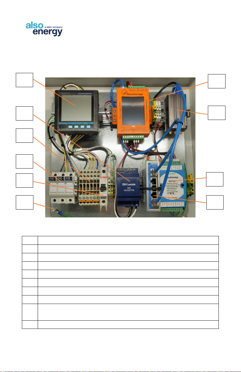
Hardware Overview
1
Revenue Grade Meter
2
DC Power Supply
3
Current Transformer Terminal Blocks
4
Voltage Reference Fused Disconnect
5
Control Power Input Terminals and Breaker
6
Grounding Stud
7
Data Logger
8
Cellular Modem (Optional)
9
RS485 and 24 VDC Surge Suppressor for External Device
Connection
10
Ethernet Switch
1
2
4
3
5
6
7
8
9
10
8
AlsoEnergy.com | 886-303-5666 | United States, Germany, Japan, India
PLCS 600 Installation Guide
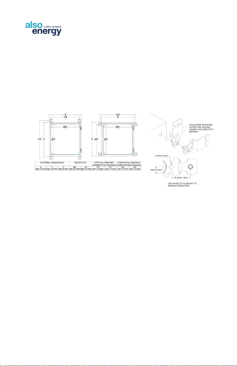
Mounting the Enclosure
Location
•The unit should be placed in a secure location, away from
any potential tampering.
•Mount to an indoor or outdoor wall using four M8 or 5/16”
bolts through the holes in the mounting flanges.
•Allow space beneath the
enclosure for conduit runs for all
input and output wires.
•Allow sufficient working space in front of and beside the
unit to allow the front door to open fully.
Distance Limitations
•Maximum 100m (328 feet) from an internet connected
network port if not using an internal cellular modem.
•No further than 2m (6 feet) from earth ground.
•Maximum 1200m (4,000 feet) between communications
enclosure and last RS-485 device
Enclosure Penetrations
•All conduits and wires must enter from the bottom of the
enclosure. Do not penetrate the top or sides of the
enclosure.

9
AlsoEnergy.com | 886-303-5666 | United States, Germany, Japan, India
PLCS 600 Installation Guide
•All entry points must be sealed using weatherproof
connecters.
•Warranty will be voided if there are entry points on the top
or sides of the enclosure.
•All penetrations must be liquid tight. Use outdoor rated
conduit connections for all outdoor installation.
•AlsoEnergy provides a desiccant packet within all
enclosures to reduce the internal humidity of the enclosure.
Replace the desiccant packet when the humidity indicator
card shows 40% relative humidity or higher.
•AC power, voltage reference, and current transformer wire
must not be run through conduit carrying RS485, CAT5e,
or analog sensor wires. Penetrate the enclosure for the two
separate conduits as shown.

10
AlsoEnergy.com | 886-303-5666 | United States, Germany, Japan, India
PLCS 600 Installation Guide
Wiring to External Connections
Control Power
•The power supply in the AlsoEnergy PLCS 600 requires
100-277VAC at 0.2A-0.4A, 50-60 Hz, and is auto-ranging.
A neutral wire is required for power, do not use two “hot”
phases to power the enclosure.
•The monitoring system should be protected by a main
circuit breaker rated up to 20 amps.
•Power may be provided from a dedicated circuit. Providing
power from the line side of the voltage reference is not
permitted in all areas. Consult NEC and local regulations if
not powering the enclosure from a dedicated breaker.
Check that power is off at the main breaker and that the
breaker inside the PLCS 600 is off before starting any work.
Complete all other enclosure connections before
energizing the enclosure.
Connect the AC input power with 12-14AWG as
follows.
(1) Circuit Breaker - AC line 100-277VAC
(black)
(2) Terminal Block –AC neutral (white)
(3) Green/Yellow Terminal Block –EGC
(green, green/yellow, or bare copper)

11
AlsoEnergy.com | 886-303-5666 | United States, Germany, Japan, India
PLCS 600 Installation Guide
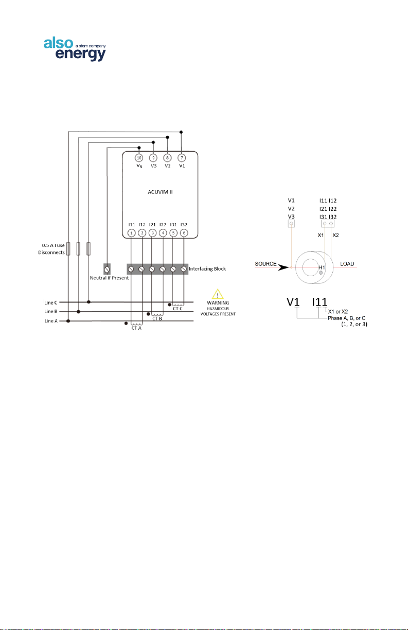
Revenue Grade Meter
Install Current Transformers (CTs) and make all connections with all
system AC and DC power turned OFF. If you have any questions, please
call AlsoEnergy technical support before turning power on.
Danger
This is a Class III Measurement Device. Line voltages
up to 600 VRMS are present on the input terminals of
the device and throughout the connected line circuits
during normal operation. These voltages may cause
severe injury or death. Installation and servicing
should be performed only by qualified, properly trained personnel.
12
AlsoEnergy.com | 886-303-5666 | United States, Germany, Japan, India
PLCS 600 Installation Guide
Current Transformer and Voltage Reference
Installation
•Place the CT around one phase of the solar generation
output so that dot or "H1" mark faces the inverter(s).
•Voltage reference and CT location should be in the same
vicinity and must not be separated by a transformer.
•CT and VT are phase-specific and must be matched when
connecting to the meter. the voltage tap "V1" must connect
to the same phase that is being measured by the CT
connected to “I11" and "I12". Similarly, "V2" is associated
with "I21" and "I22" and "V3" with "I31" and "I33".
•Observe correct polarity of the CT leads. X1 and X2 will be
labeled or color coded by the CT manufacturer.
13
AlsoEnergy.com | 886-303-5666 | United States, Germany, Japan, India
PLCS 600 Installation Guide
Terminal ID
Wire
1
Voltage Phase A (V1)
2
Voltage Phase B (V2)
3
Voltage Phase C (V3)
4
Neutral (VN)
5
CT X1 Phase A (I11)
6
CT X2 Phase A (I12)
7
CT X1 Phase B (I21)
8
CT X2 Phase B (I22)
9
CT X1 Phase C (I31)
10
CT X1 Phase C (I32)
14
AlsoEnergy.com | 886-303-5666 | United States, Germany, Japan, India
PLCS 600 Installation Guide
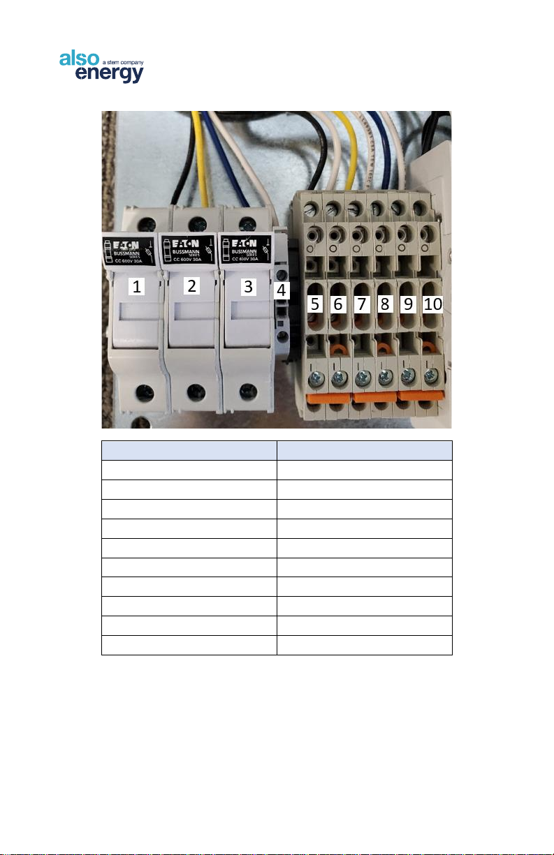
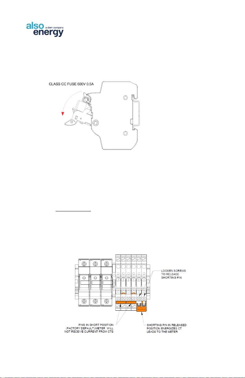
•To replace fuses or de-energize the meter voltage
reference pull down on the fuse holder. Replace fuses
with 0.5A 600V Class CC fuses.
•CT shorting pins are used to de-energize CT leads into
the meter. PLCS enclosures are shipped with pins in
the shorted position for installation. After CT leads
have been connected the pins must be released for
proper meter operation.
IMPORTANT
CTs are energized and potentially hazardous even if shorting
pins are engaged. Always de-energize measured feeders
before installing or disconnecting CTs.

15
AlsoEnergy.com | 886-303-5666 | United States, Germany, Japan, India
PLCS 600 Installation Guide
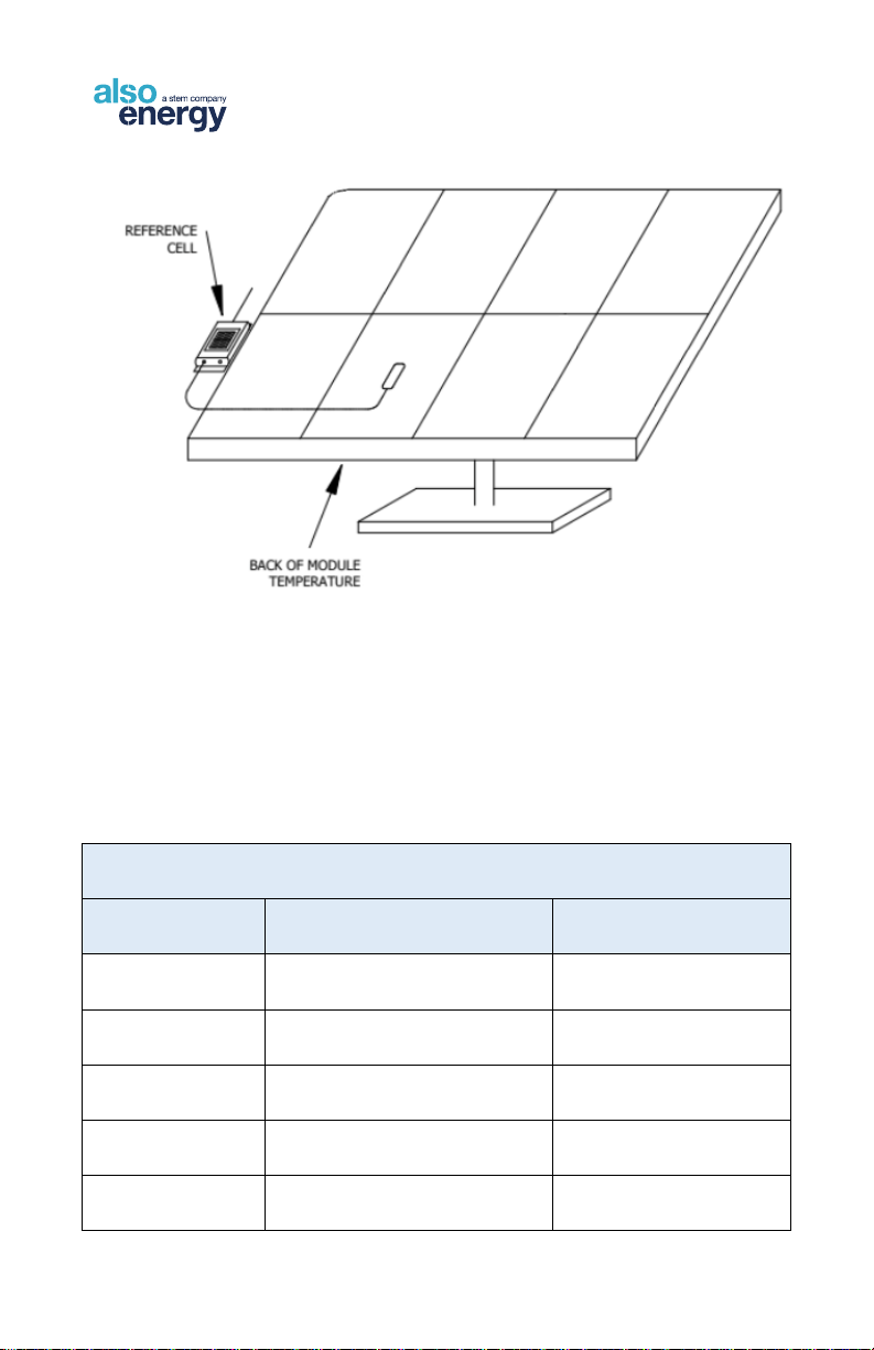
Weather Sensor Installation
IMPORTANT - DO NOT CUT, SPLICE, OR SHORTEN THE LEAD FOR
ANALOG BACK OF MODULE TEMPERATURE OR WIND SPEED SENSORS.
The sensor is calibrated, and the included cable is pre-terminated for
direct connection to the reference cell. The reference cell must be
mounted near the monitored module. Excess cable should be wrapped
and secured to the rack structure with zip ties.
Reference Cell and Back of Module Temperature
Mounting
•Mount the reference cell directly to the module frame at the
perimeter of the array.
•The reference cell can accommodate one auxiliary back of
module temperature and one wind speed sensor.
•If applicable, connect the back of module temperature and
wind speed sensor cables to the appropriate ports on the
IMT reference cell and screw the water-tight connector
firmly into place.
•The reference cell ships with a 3m cable for power and
RS485 data. The cable may be extended following RS485
daisy chain configuration best practices. All splices must
be made inside a weather-tight enclosure or using liquid-
tight connectors.
•Connect the pigtailed wires to the PLCS 600 enclosure to
the bottom of the 24VDC and RS485 surge suppressor.
•The back of module temperature sensor should be affixed
to the center of the back of the module away from the edge
of the array.
16
AlsoEnergy.com | 886-303-5666 | United States, Germany, Japan, India
PLCS 600 Installation Guide
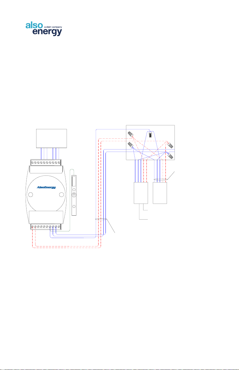
Ambient Temperature Sensor Mounting
•Mount the ambient temperature sensor outdoors in a north-
facing, always-shaded location with the sensor pointing
down.
•Connect the pigtailed wires to the bottom of the 24VDC
and RS485 surge suppressor in the PLCS 600 enclosure.
IMT RS485 and 24VDC Connections
Wire Color
Signal
PLCS 600 Terminal
Red
Supply Power Positive
+24VDC
Black
Supply Power Negative
GND
Brown
RS485 Data +
CH2 D+
Orange
RS485 Data -
CH2 D-
Black (Thick)
Shield
Shield/PE
17
AlsoEnergy.com | 886-303-5666 | United States, Germany, Japan, India
PLCS 600 Installation Guide
Weather Sensor Wiring
Each OVP-R2P1 unit provides surge protection for two RS485
busses and one 24 VDC bus.
•Field wiring must connect at the unprotected side of the
board to channel 2 of the OVP.
•One or both shield/PE terminals must be connected to
earth ground for proper operation of the surge suppressor.
DATA +
DATA -
DATA LOGGER
BROWN
ORANGE
REFERENCE
CELL
JUNCTION BOX
BLACK
RED
BLACK(THICK)
SHIELD
24VDC +
24VDC -
AMBIENT
TEMPERATURE
UNPROTECTED
PROTECTED
OVP-R2P1
+24VDC
GND
SHIELD/PE
CH1 D-
CH1 D+
CH1 COM
SHIELD/PE
CH2 D-
CH2 D+
CH2 COM
WIND SPEED
BACK OF MODULE
TEMPERATURE
DO NOT EXTEND CABLE
PROVIDED WITH SENSOR.
RS485 FROM DAS TO
JUNCTION MAY BE
EXTENDED
BROWN
ORANGE
BLACK
RED
BLACK(THICK)

18
AlsoEnergy.com | 886-303-5666 | United States, Germany, Japan, India
PLCS 600 Installation Guide
Modbus Communication Wiring
RS485 for Modbus RTU Communication
•Use Belden 3106A or equivalent shielded, twisted pair
RS485 wire.
•RS485 must be wired in a single “daisy chain”
configuration.
•If a termination resistor is to be used it must be only on the
last device in the chain.
•The PLCS 600 supports a maximum of 20 inverters.
•Avoid ground loops by landing the shield drain only at the
PLCS 600 enclosure. Never ground the shield in more
than one location.
•The total RS485 daisy chain should not exceed 4000’
(1219m) in wire length.
•RS485 connections are commonly labeled as ‘A’ or ‘B’ but
the convention is not standardized. The polarity of the
inverter daisy chain must match the datalogger, wire
according to data+ and data- as opposed to A and B. Refer
to inverter manufacturer documentation if the polarity of the
RS485 terminations is not clear. Set device Modbus
addresses per the AlsoEnergy Modbus Address Standard.

19
AlsoEnergy.com | 886-303-5666 | United States, Germany, Japan, India
PLCS 600 Installation Guide
ON
OFF
TERMINATION
RESISTOR
ON
OFF
TERMINATION
RESISTOR
LAST RS485 DEVICE
TRIM AND INSULATE
SHIELD/DRAIN AT FINAL DEVICE
IN CHAIN, DO NOT LAND OR
GROUND AT ANY POINT OTHER
THAN AT RTU CLIENT DEVICE.
USE BELDEN 3106A OR
EQUIVALENT SHIELDED,
TWISTED PAIR RS485
SPLICE SHIELD AT EACH
JUNCTION. INSULATE
CONNECTION AND DO
NOT LAND OR GROUND.
DATA +
DATA -
DATA COMMON
ON
OFF
TERMINATION
RESISTOR
TERMINATION RESISTOR NOT TYPICALLY
USED FOR 9600 BAUD COMMUNICATION.
IF USED THEN ENSURE THAT ONLY THE
FINAL DEVICE IN A DAISY CHAIN USES
THE TERMINATION RESISTOR. ALL
OTHERS MUST BE SET TO 'OFF.'
DATA LOGGER
UNPROTECTED
PROTECTED
OVP-R2P1
+24VDC
GND
SHIELD/PE
CH1 D-
CH1 D+
CH1 COM
SHIELD/PE
CH2 D-
CH2 D+
CH2 COM
Correct RS485 daisy chain configuration must be followed, avoid star or
branch configurations. S tubs should be kept as short as possible never
exceeding 50’ (15m).
RTU
CLIENT
RTU
SERVER RTU
SERVER RTU
SERVER
RTU
SERVER
CORRECT
RTU
CLIENT
RTU
SERVER RTU
SERVER
RTU
SERVER
RTU
SERVER RTU
SERVER
RTU
SERVER
INCORRECT
RTU
CLIENT
RTU
SERVER
RTU
SERVER
RTU
SERVER
INCORRECT
RTU
SERVER
RTU
SERVER

20
AlsoEnergy.com | 886-303-5666 | United States, Germany, Japan, India
PLCS 600 Installation Guide
CAT5e Ethernet for Modbus TCP Communication
•Use Belden 7919A or equivalent shielded CAT5e cable for
all ethernet connections.
•Snap the RJ45 connectors into the PLCS 600 network
switch and the inverter communication module.
•Each device must be assigned a static IP address on the
network. If the PLCS 600 was purchased with the modem
configure devices with the following gateway and subnet
mask, configure IP address per the AlsoEnergy Modbus
Address Standard.
Default Gateway
192.168.13.1
Subnet Mask
255.255.255.0
If using an existing network, you must obtain network configuration and
one static IP address for each Modbus TCP connected device from the
network administrator.
AlsoEnergy Modbus Address Standard
Each device must be configured with a unique Modbus ID or IP address.
•For all devices using Modbus RTU (RS485)
communication protocol, configure the device ID per the
table below using the first number in the range for each
device and incrementing.
oExample:
Production Meter 1 –Address 41
Production Meter 2 –Address 42
Consumption Meter –Address 43
•Configure the rs485 bus for 9600 Baud Rate, 8 data bits,
No Parity, and 1 stop bit (9600 8N1).
Table of contents
Popular Inverter manuals by other brands

Whistler
Whistler GO AC PP150AC owner's manual

Viper
Viper DF-100A-EU operating instructions

Vector
Vector MAXX SST VEC053D Owner's manual & warranty information

oventrop
oventrop Regtronic RQ Installation and operating instructions for the specialised installer

ExelTech
ExelTech XP600 Installation and operation manual

Goodwe
Goodwe XS Series user manual


Sealey
Sealey PI1000.V4 Instructions for use

Eaton
Eaton Cutler-Hammer SPI9000 user manual

Amerec
Amerec Steambath Generator AK5 owner's manual

Alpha Group
Alpha Group OutBack Power GS3548E installation manual

Solplanet
Solplanet ASW H-S2 Series user manual

Generac Power Systems
Generac Power Systems QuietSource 004917-5 Installation and owner's manual