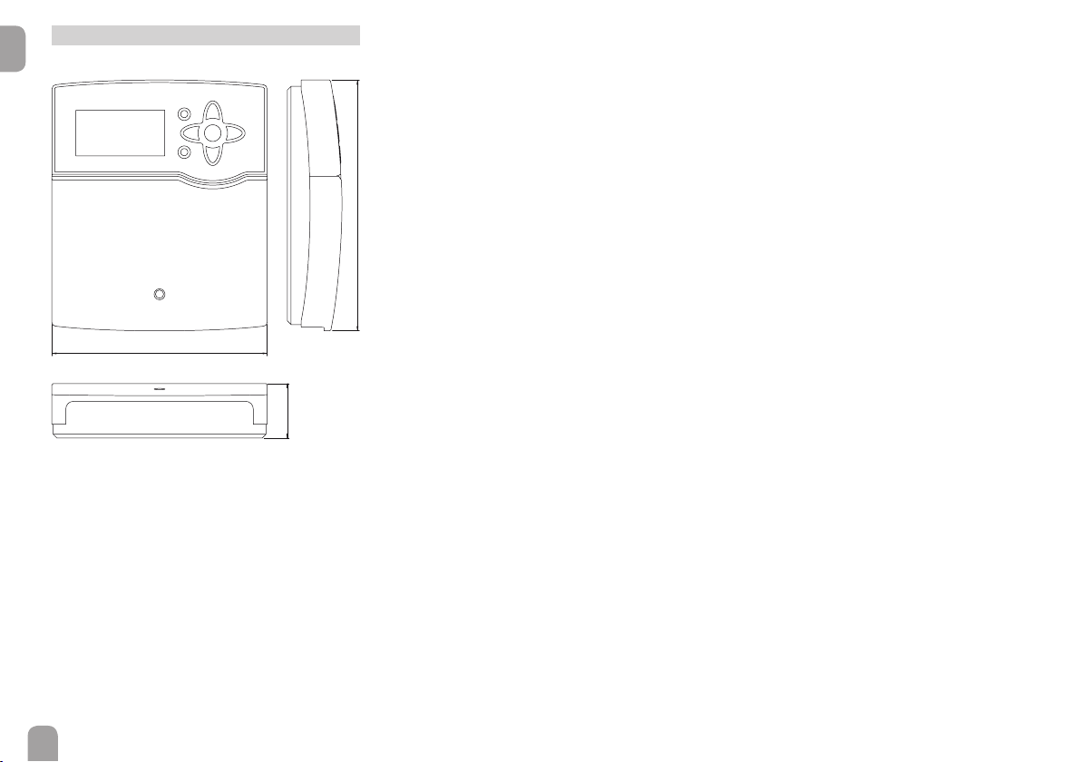
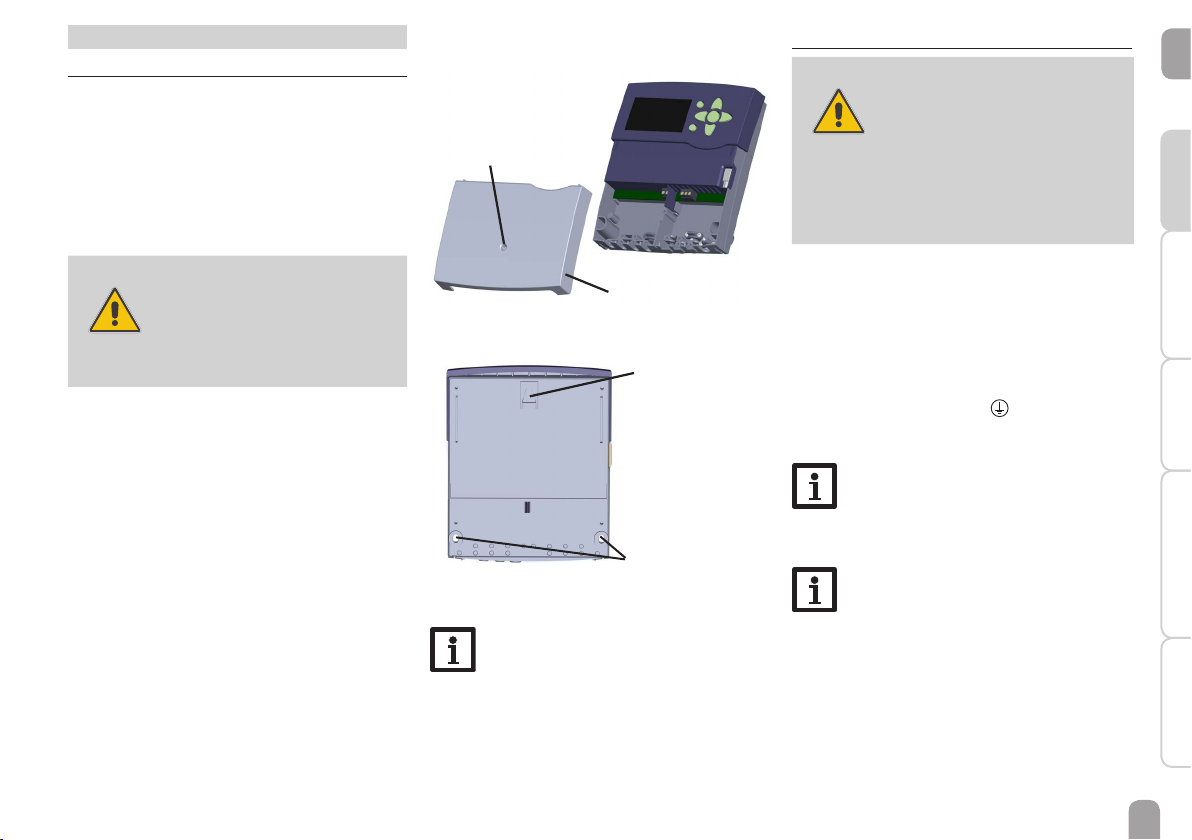
oventrop Regtronic RQ Operating instructions

*11209024*
11209024
Valves, controls + systems
”Regtronic RQ“
Installation and operating instructions for the specialised installer
EN
Please read this manual carefully to get the best performance from this unit.
Please keep this manual carefully.
IT
Istruzioni d’installazione e funziona-
mento per l’installatore qualifi cato
Le istruzioni complete sono disponibili nel
seguente link: www.oventrop.com
http://www.oventrop.de/qr/138103081#IT
ES
Instrucciones de instalación y opera-
ción para el instalador especializado
El manual de instrucciones completo
se puede consultar en el siguiente link:
www.oventrop.com
http://www.oventrop.de/qr/138103081#ES
RU
Инструкция по монтажу и эксплуа-
тации для специалистов
Полное руководство по эксплуатации
можно найти по следующей ссылке:
www.oventrop.com
http://www.oventrop.de/qr/138103081#RU
CS
Montážní a provozní návod pro od-
borné pracovníky
Úplný návod k obsluze najdete na:
www.oventrop.com
http://www.oventrop.de/qr/138103081#CS

2
en
Target group
These instructions are exclusively addressed to au-
thorised skilled personnel.
Only qualied electricians should carry out electri-
cal works.
Initial installation must be effected by the system
owner or qualied personnel named by the system
owner.
Description of symbols
WARNING! Warnings are indicated with a
warning triangle!
ÎThey contain information
on how to avoid the danger
described.
Signal words describe the danger that may occur,
when it is not avoided.
• WARNING means that injury, possibly life-
threatening injury, can occur.
• ATTENTION means that damage to the appli-
ance can occur.
Note:
Notes are indicated with an information
symbol.
ÎArrows indicate instruction steps that should be
carried out.
Safety advice
Please pay attention to the following safety advice
in order to avoid danger and damage to people and
property.
Instructions
Attention must be paid to the valid local standards,
regulations and directives!
Information about the product
Proper usage
The solar controller is designed for use in the Regu-
maq DHW exchange module in compliance with the
technical data specied in this manual.
Improper use excludes all liability claims.
CE-Declaration of conformity
The product complies with the relevant di-
rectives and is therefore labelled with the
CE mark.
Note:
Strong electromagnetic elds can impair the
function of the controller.
ÎMake sure the controller as well as the
system are not exposed to strong elec-
tromagnetic elds.
Subject to technical change. Errors excepted.
© 20160406_11209024_Oventrop_Regtronic_RQ_HE.monen.indd
Disposal
• Dispose of the packaging in an environmentally
sound manner.
• Dispose of old appliances in an environmentally
sound manner. Upon request we will take back
your old appliances bought from us and guarantee
an environmentally sound disposal of the devices.

3
en
RQ
Contents
1 Installation..................................................5
1.1 Mounting......................................................... 5
1.2 Electrical connection.................................... 5
2 Commissioning ..........................................7
2.1 Step-by-step parameterisation................... 7
2.1.1 Overview of relay and sensor al-
location ...............................................7
2.2 Operation and function............................... 8
2.2.1 Buttons................................................8
2.2.2 Selecting menu points and adjusting
values ..................................................8
2.2.3 Adjusting the timer ...................... 10
2.2.4 Menu structure............................... 12
2.3 Commissioning menu ................................13
3 Adjustments.............................................15
3.1 Main menu....................................................15
3.2 Status menu..................................................15
3.2.1 Meas. / Balance values.................... 15
3.2.2 Hot water........................................ 16
3.2.3 Circulation....................................... 16
3.2.4 Afterheating .................................... 16
3.2.5 Disinfection..................................... 16
3.2.6 Additional functions ...................... 16
3.2.7 Messages.......................................... 16
3.2.8 Service.............................................. 16
3.3 Main functions .............................................17
3.3.1 Hot water........................................ 17
3.3.2 Circulation....................................... 22
3.3.3 Afterheating .................................... 24
3.3.4 Disinfection..................................... 25
3.4 Additional functions ...................................28
3.5 Basic settings................................................32
3.6 SD card .........................................................32
3.7 Manual mode ...............................................34
3.8 User code.....................................................35
3.9 Inputs............................................................. 35
4 Data communication...............................36
4.1 Data communication / Bus.........................36
4.2 SD card slot .................................................36
5 Troubleshooting .......................................37
6 Overview of parameters .........................38
7 Index .........................................................39
Navigator
Installation page 5
For mounting and connecting the controller, see
page 5.
Commissioning page 7
For installing and commissioning the controller, see
page 7.
Adjustments page 15
For making adjustments in the main and additional
functions, see page 15.
Data communication page 36
For establishing communication to the controller,
see page 36.
Troubleshooting page 37
For diagnostics and troubleshooting in the case of
an error, see page 37

4
en
Overview
Technical data
Housing: plastic, PC-ABS and PMMA
Protection type: IP 20 / EN 60529
Protection class: I
Ambient temp.: 0 … 40 °C
Dimensions: 170 x 198 x 43 mm
Mounting: wall mounting, also suitable for mounting
into patch panels
Display: Full graphic display, control lamp (direction-
al pad) and background illumination
Operation:
7 push buttons at the front of the housing
Functions: Controller for DHW heating. Functions
such as: Circulation (demand, thermostatic, perma-
nent), store afterheating (absolute, relative), thermal
disinfection, sliding temperature control, heat pump
mode, blocking protection, heat quantity measure-
ment, stratied return, error relay, function blocks,
data logging onto SD card, rmware updates over SD
card.
170
198
43
Inputs:
8 inputs for Pt1000 temperature sensors, input for
1 digital Grundfos Direct Sensor™VFD2 - 40 l Fast
Outputs: 4 semiconductor relays, 1 PWM output
Interfaces: S-Bus, SD card slot
Power supply: 100 … 240 V~, 50 … 60 Hz
Switching capacity per relay:
1 (1) A 100…240 V~ (semiconductor relay)
Total switching capacity: 4 A
Standby power consumption: 1,26 W
Mode of operation: type 1.Y
Degree of pollution: 2
Rated impulse voltage: 2,5 kV
Supply connection: type Y attachment

en
Installation
5
CommissioningAdjustmentsTroubleshooting Data communication
cover
screw
lower fastening point
upper fastening point
1 Installation
1.1 Mounting
The RQ DHW controller is already integrated in the
Regumaq DHW exchange module. If the controller is
to be installed outside of the DHW exchange mod-
ule, please mind the following instructions.
The controller must additionally be supplied from a
double pole switch with contact gap of at least 3mm.
Please pay attention to separate routing of sensor
cables and mains cables.
WARNING! Electric shock!
Upon opening the housing, live
parts are exposed!
ÎAlways disconnect the con-
troller from power supply
before opening the housing!
In order to mount the device to the wall, carry out
the following steps:
ÎUnscrew the cross-head screw from the cover
and remove it along with the cover from the
housing.
ÎMark the upper fastening point on the wall. Drill
and fasten the enclosed wall plug and screw leav-
ing the head protruding.
ÎHang the housing from the upper fastening point
and mark the lower fastening points (centres
150 mm).
ÎInsert lower wall plugs.
ÎFasten the housing to the wall with the lower
fastening screws and tighten.
ÎCarry out the electrical wiring in accordance
with the terminal allocation, see chap. 1.2.
ÎPut the cover on the housing.
ÎAttach with the cross-head screw.
1.2 Electrical connection
ATTENTION! ESD damage!
Electrostatic discharge can lead to
damage to electronic components!
ÎTake care to discharge
properly before touching
the inside of the device!To
do so, touch a grounded
surface such as a radiator
or tap!
The controller is equipped with 4 relays in total to
which loads such as pumps, valves, etc. can be con-
nected:
Relays 1 … 4 are semiconductor relays, designed for
pump speed control:
Conductor R1 … R4
Neutral conductor N (common terminal block)
Protective earth conductor PE (common terminal
block)
Note:
Connecting the device to the power supply
must always be the last step of the instal-
lation!
Note:
The minimum pump speed must be set to
100 % when non-speed-controlled devices
such as valves are connected.
Note:
Strong electromagnetic elds can impair
the function of the controller.
Make sure the controller as well as the sys-
tem are not exposed to strong electromag-
netic elds.

en
6
Installation Commissioning Adjustments Troubleshooting
Data communication
S1
S2
S3
S4
S5
S6
S7
S8
R4
IP20
N
R1-R4
100 ... 240 V~
50-60 Hz
T4A
1 (1) A (100 ... 240) V~
R3
R2
R1
L' L
GND
Temp. Sensor
PWM/0-10V
N
Isolate mains before removing cover!
Vor Öffnen Gerät spannungslos schalten!
Use ground common terminal block
Masse-Sammelklemme benutzen
Use neutral conductor common terminal block
Neutralleiter-Sammelklemme benutzen!
Use PE Common terminal block
Schutzleiter-Sammelklemme benutzen
VFD
S-Bus
S-Bus
GND
Input for digital
Grundfos Direct Sensor™
PWM (0 - 10 V) terminal
Sensor ground common
terminal block
Sensor terminals
Protective conductor
common terminal block (PE)
Neutral conductor
common terminal block
Mains and sensor cables are already connected to
the device.
Additional temperature sensors (S3 to S8) can
be connected to the terminals S3 … S8 and GND
(either polarity).
Temp. Sensor
T4A
100 ... 240 V~
50-60 Hz
1 (1) A (100 ... 240) V~
4 (1) A 240 V~
R1-R4
R5
L
R3
R2
R1
GND
S1
S2
S3
S4
S5
S6
S7
S8
CS10
V40/S9
VBus
N
R4
R5
L'
VFD
PWM/0-10V
R5
Vor Öffnen Gerät spannungslos schalten!
Isolate mains before removing cover!
Masse-Sammelklemme benutzen
Use ground common terminal block
Neutralleiter-Sammelklemme benutzen!
Use neutral conductor common terminal block
Schutzleiter-Sammelklemme benutzen
Use PE Common terminal block
!
N
RPD
IP20
4 (1) A 24V
VN: 1.0
Connect the digital Grundfos Direct Sensor™
VFD 2-40 l Fast to the input marked VFD.
S-Bus
Note:
The cables of the controller are pre-connect-
ed. chap. 1.2 is for information purposes only.
Make sure the hydraulic system is properly
grounded!
Note:
For more details about the initial commis-
sioning procedure, see page 7.
Temp. Sensor
T4A
100 ... 240 V~
50-60 Hz
1 (1) A (100 ... 240) V~
4 (1) A 240 V~
R1-R4
R5
L
R3
R2
R1
GND
S1
S2
S3
S4
S5
S6
S7
S8
CS10
V40/S9
VBus
N
R4
R5
L'
VFD
PWM/0-10V
R5
Vor Öffnen Gerät spannungslos schalten!
Isolate mains before removing cover!
Masse-Sammelklemme benutzen
Use ground common terminal block
Neutralleiter-Sammelklemme benutzen!
Use neutral conductor common terminal block
Schutzleiter-Sammelklemme benutzen
Use PE Common terminal block
!
N
RPD
IP20
4 (1) A 24V
VN: 1.0
Note:
When Grundfos Direct SensorsTM are used,
the sensor ground common terminal block
must be connected to PE.
Te mp. Sensor
T4A
100 ... 240 V~
50-60 Hz
1 (1) A (100 ... 240) V~R1-R4
L
R3
R2
R1
GND
S1
S2
S3
S4
S5
S6
S7
S8
S-Bus
N
R4
L'
VFD
Vor Öffnen Gerät spannungslos schalten!
Isolate mains before removing cover!
Masse-Sammelklemme benutzen
Use ground common terminal block
Neutralleiter-Sammelklemme benutzen!
Use neutral conductor common terminal block
Schutzleiter-Sammelklemme benutzen
Use PE Common terminal block
!
N
IP20
VN: 1.0
The controller is supplied with power via a mains
cable. The power supply of the device must be
100 … 240V~ (50 … 60 Hz).
The mains connection is at the following terminals:
• Neutral conductor N
• Conductor L
• Protective earth conductor ⏚(common terminal
block)
WARNING! Electric shock!
L' is a fused contact permanently
carrying voltage.
ÎAlways disconnect the de-
vice from power supply be-
fore opening the housing!

en
7
Installation
CommissioningAdjustmentsTroubleshooting Data communication
2 Commissioning
When the hydraulic system is lled and ready for op-
eration, connect the controller to the mains.
The controller runs an initialisation phase in which
the directional pad ashes red.
When the controller is commissioned for the rst
time or when it is reset (see page 32), it will run
a commissioning menu after the initialisation phase.
The commissioning menu leads the user through the
most important adjustment channels needed for op-
erating the system. For navigating in the commission-
ing menu, see page 8.
2.1 Step-by-step parameterisation
a. Running the commissioning menu
The commissioning menu is run after the rst con-
nection and after every reset (see page 32). It will
request the following basic adjustments:
• Menu language
• Time
• Date
• Circulation
• Afterheating
• Disinfection
When the last item Save at the end of the commis-
sioning menu is selected, a security enquiry appears.
If the safety enquiry is conrmed, the adjustments
are saved. For further information about the com-
missioning menu see page 13.
Relay / sensor allocation
Terminal Description Display screens
R4 + PWM Primary pump R4
R2 Circulation pump R2
S1 Store ow sensor T-store ow
S2 Hot water ow sensor T-HW
VFD Cold water sensor T-CW
VFD Circulation ret. sensor T-circ return
Terminal Description Display screens
R4 + PWM Primary pump R4
S1 Store ow sensor T-store ow
S2 Hot water ow sensor T-HW
VFD Cold water sensor T-CW
VFD Flow rate sensor Flow rate
b. Activating the main functions
Adjustments for the main functions Circulation,
Afterheating and Disinfection can be made. Main
functions that have not been activated in the com-
missioning menu can now be activated here.
Free relays can be allocated to main functions which
require a relay.The controller always suggests the nu-
merically smallest free relay.
Sensors can be allocated to more than one function.
For further information about the main functions see
page 17.
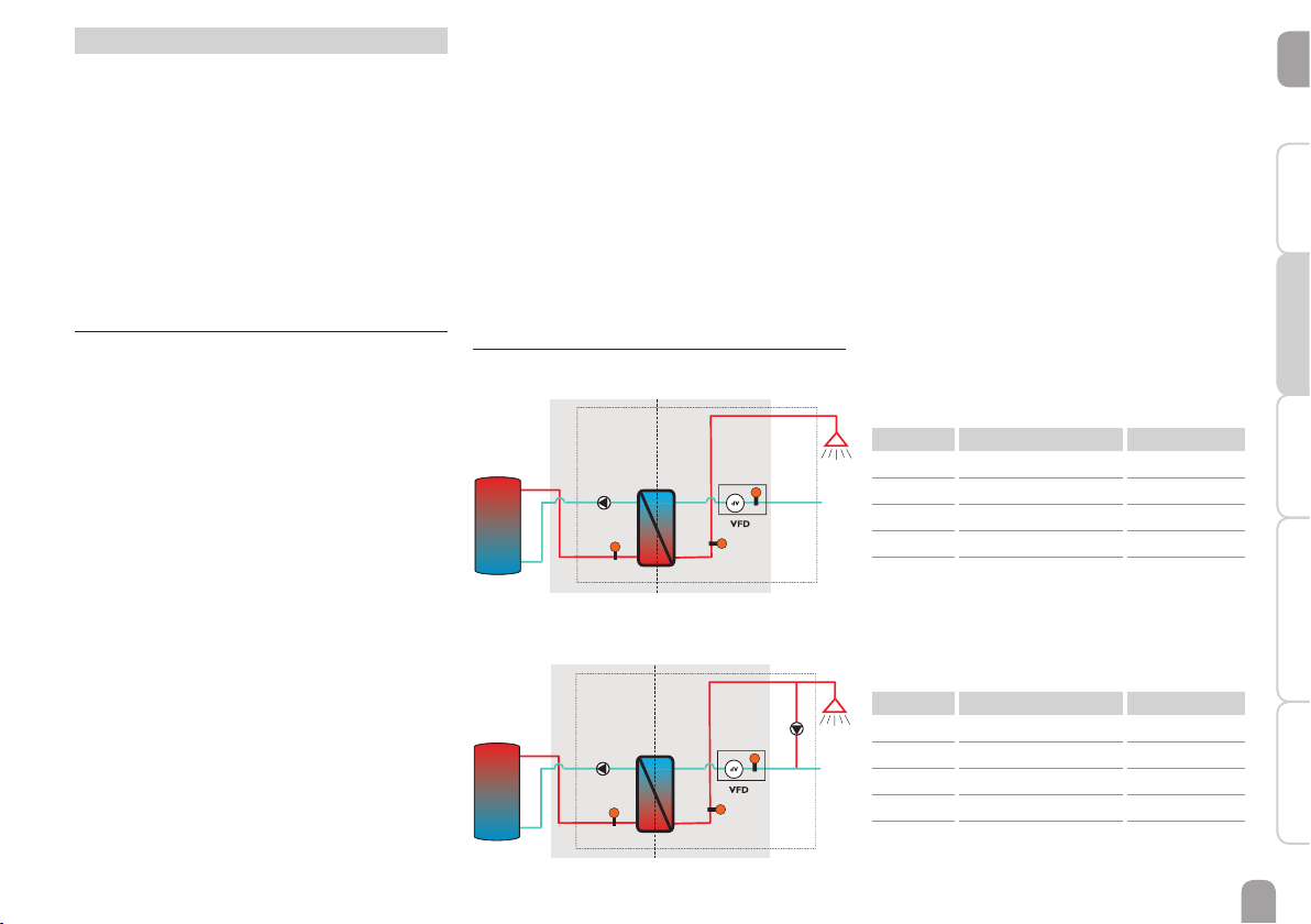
2.1.1 Overview of relay and sensor allocation
DHW heat exchange module without circula-
tion
Primärseite Sekundärseite
R4/PWM
S1 S2
primary side secondary side
DHW heat exchange module with circulation
Primärseite Sekundärseite
R4/PWM
S1 S2
R2
primary side secondary side
c. Activating additional functions
Only after the required main functions have been ac-
tivated and adjusted, should the additional functions
be activated.
Any free relay can be allocated to any of the main
functions.The controller always suggests the numeri-
cally smallest free relay.
Sensors can be allocated to more than one function.
For further information about the additional func-
tions see page 28.

en
8
Installation Commissioning Adjustments Troubleshooting
Data communication
2.2 Operation and function
2.2.1 Buttons
The controller is operated via the 7 buttons next to
the display.They have the following functions:
Button ❶- scrolling upwards
Button ❸- scrolling downwards
Button ❷- increasing adjustment values
Button ❹- reducing adjustment values
Button ➄ - con rming
Button ➅- entering the status menu
Button ➆- escape button for changing into the
previous menu
1
2
4
63
5
7
2.2.2 Selecting menu points and adjusting
values
During normal operation of the controller, the dis-
play is in the main menu. If no button is pressed for a
few seconds, the display illumination goes out.
Press any key to reactivate the display illumination.
ÎIn order to scroll though a menu or to adjust a
value, press either buttons ❶and ❸or buttons
❷and ❹
ÎTo open a sub-menu or to con rm a value, press
button ➄
ÎTo enter the status menu, press button ➅– un-
con rmed adjustment will not be saved
ÎTo switch one menu level upwards, press button
➆ – uncon rmed adjustment will not be saved
If no button has been pressed within a couple of
minutes, the adjustment is cancelled and the previ-
ous value is retained.
If the symbol »is shown behind a menu item, press-
ing button ➄will open a new sub-menu.
If the symbol ➕is shown in front of a menu item,
pressing button ➄will open a new sub-menu. If it is
already opened, a ➖is shown instead of the ➕.

en
9
Installation
CommissioningAdjustmentsTroubleshooting Data communication
Values and adjustments can be changed in different
ways:
current value savedminimum value maximum value
adjusted value
(not yet con rmed)
adjustment channel
Numeric values can be adjusted by means of a slide
bar. The minimum value is indicated to the left, the
maximum value to the right.The large number above
the slide bar indicates the current adjustment. By
pressing buttons ❷or ❹the upper slide bar can be
moved to the left or to the right.
Only after the adjustment has been con rmed by
pressing button ➄will the number below the slide
bar indicate the new value. The new value will be
saved if it is con rmed by pressing button ➄again.
The display jumps back to the former menu level.
inactive area
minimum
value
active area
maximum
value
When two values are locked against each other, they
will display a reduced adjustment range depending on
the adjustment of the respective other value.
In this case, the active area of the slide bar is short-
ened, the inactive area is indicated as a dotted line.
The indication of the minimum and maximum values
will adapt to the reduction.
If only one item of several can be selected, they will
be indicated with "radio buttons". When one item
has been selected, the radio button in front of it is
lled. The selection will be saved if it is con rmed by
pressing button ➄again.The display jumps back to
the former menu level.
Some menu items are indicated with chackboxes.
When an item has been selected, an xappears inside
the checkbox.

en
10
Installation Commissioning Adjustments Troubleshooting
Data communication
2.2.3 Adjusting the timer
When the Timer option is activated, a timer is in-
dicated in which time frames for the function can be
adjusted.
First of all, an overview of the current adjustments
is displayed. For each day of the week there is an
overview display. The display can be switched back
and forth between the different days by pressing but-
tons ❷or ❹.
In order to adjust the timer, press button ➄.
First the individual days of the week or all days of the
week can be selected.
The last menu item after the list of days is Continue.
If Continue is selected, the Edit timer menu opens,
in which the time frames can be adjusted.
Adding a time frame:
The time frames can be adjusted in steps of 15 min-
utes.
In order to add an active time frame, proceed as fol-
lows:
ÎMove the cursor to the desired starting point of
the time frame by pressing buttons ❷and ❹.
Con rm the starting point of the time frame by
pressing button ❶.
ÎMove the cursor to the desired ending point of
the time frame by pressing buttons ❷and ❹.
ÎThe end of a time frame can be determined by
pressing button ➄.
ÎIn order to add another time frame, repeat the
last three steps.
Note:
In order to adjust a 24 h time frame, press
button ❶once during the adjustment pro-
cess.
ÎIn order to get back to the overview of current
adjustments, press button ➄again.

en
11
Installation
CommissioningAdjustmentsTroubleshooting Data communication
Removing a time frame:
In order to remove an active time frame, proceed
as follows:
ÎDetermine the point from which on the time
frame is to be removed by pressing button ❸.
ÎMove the cursor to the desired ending point of
the time frame by pressing buttons ❷and ❹.
ÎIn order to conclude removing the time frame,
press button ➄upon reaching the desired end-
ing point.
ÎIn order to get back to the overview of current
adjustments, press button ➄again.

en
12
Installation Commissioning Adjustments Troubleshooting
Data communication
2.2.4 Menu structure
Main menu
Status
Hot water
Circulation
Afterheating
Disinfection
Additional functions
Basic setting
SD card
Manual mode
User code
Inputs
Hot water
Emergency operation
T-HW set
Set min
Set max
∆Tmax
HX start
T-HW set sliding
HP (heat pump)
Blocking protection
Circulation
Circ. mode
Timer
Additional functions
Fct. block 1
Fct. block 2
Error relay
Stratied return
Afterheating
AH
The menu items and adjustment values selectable are
variable depending on adjustments already made.The
gure only shows an exemplary excerpt of the com-
plete menu in order to visualise the menu structure.
Basic settings
Language
Auto DST
Date
Time
T-display standby
Factory setting
Status
Meas./ Balance values
Hot water
Circulation
Afterheating
Disinfection
Function block 1
Function block 2
Stratied return
Error relay
Messages
Service
back
Disinfection
Manual start
T-disinf set
Disinf duration
Disinf day
Disinf time
Preheating
∆t circ
Overrun time
Flushing

en
13
Installation
CommissioningAdjustmentsTroubleshooting Data communication
1. Language:
ÎAdjust the desired menu language.
3. Time:
ÎAdjust the clock time. First of all adjust the
hours, then the minutes.
4. Date:
ÎAdjust the date. First of all adjust the year, then
the month and then the day.
2. Daylight savings time adjustment:
ÎActivate or deactivate the automatical daylight
savings time adjustment.
2.3 Commissioning menu
The commissioning menu consists of the channels
described here. They can be entered and adjusted
line by line.

en
14
Installation Commissioning Adjustments Troubleshooting
Data communication
8. Completing the commissioning menu:
If the security enquiry is con rmed, the adjustments
are saved.
ÎIn order to con rm the security enquiry, select
Ye s and press button ➄.
ÎIn order to get back to the parameters of the
commissioning menu, select No or press but-
ton ➆.
When the security enquiry has been con rmed, the
controller is ready for operation.
All adjustments made in the commissioning menu
can, if necessary, be changed later on in the corre-
sponding menus.
5. Circulation:
ÎActivate the circulation and select the circula-
tion mode.
For detailed information see page 22.
7. Thermal disinfection:
ÎActivate the thermal disinfection. More adjust-
ments for this function can be made when the
commissioning menu has been completed.
For detailed information see page 25.
Note:
In order to use the thermal disinfection
function, the circulation function has to be
activated.
6. Afterheating:
ÎActivate the store afterheating.Adjust the after-
heating mode, the reference sensor and the relay
that is to be switched.
For detailed information see page 24.

en
15
Installation
CommissioningAdjustmentsTroubleshooting Data communication
3.2 Status menu
In the Status menu of the controller, the status mes-
sages for every menu area can be found.
3.2.1 Meas. / Balance values
In the Status / Meas./ Balance values menu, all
current measurement values as well as a range of
balance values are displayed. Some of the menu items
can be selected in order to enter a sub-menu.
All measured values for the main and additional func-
tions, the allocation of sensors and relays as well as
the operating hours counter are displayed.
If, for example, Hot water is selected, a sub-menu
with the sensors and relays allocated to the system
will open. In the sub-menu, the current temperatures
and the current pump speed are indicated.
When a line with a measurement value is selected,
another sub-menu will open.
If, for example, VFD is selected, a sub-menu indicat-
ing the minimum and maximum values will open.
When the item Chart is selected, a progression
chart appears.
The progression chart shows the development at the
corresponding sensor over the last 24 hours. Press
buttons ❷and ❹to switch back and forth between
a chart of the current day and one of the day before.
3 Adjustments
3.1 Main menu
In this menu, the different menu areas can be se-
lected.
The following menus are available:
Status
Hot water
Circulation
Afterheating
Disinfection
Additional functions
Basic setting
SD card
Manual mode
User code
Inputs
Note:
If no button is pressed for the adjustable
time T-display standby (see page 32),
the display illumination goes out. After 3
more minutes, the controller switches to
the Status menu.
ÎIn order to get from the Status / Hot
water menu into the Main menu, press
button ➆.

en
16
Installation Commissioning Adjustments Troubleshooting
Data communication
3.2.2 Hot water
In the Status / Hot water menu, the status of the
DHW heating is indicated.
3.2.3 Circulation
In the Status / Circulation menu, the status of the
circulation, the circulation mode selected as well as,
if applicable, remaining runtimes and blocking times
are indicated.
3.2.4 Afterheating
In the Status /Afterheating menu, the status of
the afterheating as well as the afterheating mode se-
lected are indicated.
3.2.7 Messages
In the Status / Messages menu, error and warning
messages are indicated.
During normal operation, the message Everything
OK is indicated.
A line break or short circuit in a sensor line is in-
dicated as !Sensor fault. A precise error code can
be found in the Status / Meas.- / Balance values
menu.
In the case of an error, the LED of the directional
pad ashes red.
3.2.8 Service
In the Status / Service menu, each sensor and relay
is indicated with the component or function it has
been allocated to.
Relays and sensor inputs that are not used will not
be indicated here.
3.2.5 Disinfection
In the Status / Disinfection menu, the status and
the progression of the thermal disinfection, different
runtimes as well as the number of starting processes
are indicated.
3.2.6 Additional functions
In this position, status menus for additional functions
appear, if additional functions have been activated.
The menu items appear with the name of the cor-
responding function:
• Fct. block 1
• Fct. block 2
• Strati ed return
• Error relay
In the corresponding menu, status values of the se-
lected function are indicated.

en
17
Installation
CommissioningAdjustmentsTroubleshooting Data communication
Emergency operation
The Emergency operation function can be used
for ensuring the DHW supply in the case of a sensor
fault. In this case, the primary pump will be perma-
nently run at the adjustable Emergency speed. For
this function, the emergency speed must be aligned
with the resulting hot water temperature.The display
channel T-HW enables this alignment directly in the
Hot water menu, as soon as the emergency opera-
tion has been activated.
Note:
If a sensor fault that inhibits DHW heat-
ing has occurred, activate the emergency
operation in the Emergency op. channel.
In order to ensure a quick entry to emergency oper-
ation in the case if an emergency, perform the align-
ment of the emergency speed as early as possible.
The emergency speed is also available for selection
in the R4 adjustment channel of the manual mode
menu.This way, the speed of the primary pump can
be limited for manual operation in order to ensure a
scald protection.
Adjustment channel Description Adjustment range / selection Factory setting
Emergency op. Activation of the function Yes, No No
Emergency speed Pump speed for emergency operation 1.5 … 100.0 % 12.0 %
T-HW
Indication of the current hot water
ow temperature for the offset of the
emergency speed
- -
back
Main menu / Hot water / Emergency op.
3.3 Main functions
3.3.1 Hot water
In this menu, all adjustments for the DHW heating
can be made.The following parameters and functions
are available:
• Emergency operation
• Hot water set temperature
• Minimum hot water set temperature
• Maximum hot water set temperature
• Maximum exceedance of the hot water set
temperature
• Heat exchanger mode start
• Sliding hot water set temperature
• Heat pump mode
• Blocking protection

en
18
Installation Commissioning Adjustments Troubleshooting
Data communication
Hot water set temperature (T-HW set)
This parameter can be used for adjusting the T-HW
set temperature which is to be reached at the HW
ow sensor S2. The controller then determines the
pump speed of the primary pump such that the tem-
perature at the HW ow sensor on the secondary
side continuously keeps the required set tempera-
ture T-HW set.
Adjustment channel Description Adjustment range / selection Factory setting
T-HW set Hot water set temperature (T-HW set) 20 … 75 °C 60 °C
Main menu / Hot water / T-HW set
Minimum hot water set temperature
Maximum hot water set temperature
This parameter determines the minimum limitation
for the adjustment of the hot water set temperature
T-HW set.
Note:
In order to prevent the hot water set tem-
perature from being adjusted too low, Set
max must be adjusted to suit the system
upon commissioning!
This parameter determines the maximum limitation
for the adjustment of the hot water set temperature.
Note:
In order to prevent the hot water set tem-
perature from being adjusted too high, Set
max must be adjusted to suit the system
upon commissioning!
Adjustment channel Description Adjustment range / selection Factory setting
Set min Minimum hot water set temperature 20 … 75 °C 20 °C
Adjustment channel Description Adjustment range / selection Factory setting
Set max Maximum hot water set temperature 20 … 75 °C 60 °C
Main menu / Hot water / Set max

en
19
Installation
CommissioningAdjustmentsTroubleshooting Data communication
Maximum limitation for exceedance of the hot water set temperature (T-HW set)
This function can be used for preventing draw-off
water temperatures that massively exceed the hot
water set temperature (scald protection).
Note:
The switch-on condition for the maximum
limitation will only become valid if the hot
water ow temperature is >= 60°C.
When the temperature measured at the HW ow
sensor S2 exceeds the hot water set temperature
T-HW set by the maximum temperature difference
∆Tmax, the primary pump R4 is switched off.
Example:
T-HW > T-HW set + ∆Tmax Îprimary pump off
When the maximum limitation is active, no DHW
heating takes place. In the Status / Messages menu, the
error message Emergency shutdown appears. In or-
der to enable DHW heating again, acknowledge the
error message by pressing button (5).
Note:
The maximum limitation will not become
active during and up until 1 hour after the
completion of a thermal disinfection.
Note:
The maximum limitation does not affect the
control of the circulation pump.
Adjustment channel Description Adjustment range / selection Factory setting
Max. limitation Maximum limitation option Yes, No Ye s
tmax Switch-on condition time period 5 … 300 s 180 s
∆Tmax Maximum exceedance of the hot
water set temperature T-HW set 3.0 … 8.0 K 5.0 K
Main menu / Hot water / ∆Tmax

en
20
Installation Commissioning Adjustments Troubleshooting
Data communication
Sliding set value
The Sliding set value function can be used for
adapting the hot water set temperature in the case of
insuf cient store temperature. The function prevents
the primary pump from being run at 100 %, which
would unnecessarily mix the store contents and thus
destroy the store strati cation.
If the store ow temperature falls below the limit
value T-HWset + ∆T sliding, T-HW set will be
Adjustment channel Description Adjustment range / selection Factory setting
T-HW set sl. Activation of the function Yes, No No
∆T sliding Temperature difference 2.0 … 20.0 K 5.0 K
back
Main menu / Hot water / Sliding set value
Heat exchanger mode
The HX start sub-menu can be used to adjust all
values for the operation of the heat exchanger.
3 heat exchanger modes are available. They enable
different temperature conditions of the heat ex-
changer at the beginning of a draw-off.
Adjustment channel Description Adjustment range / selection Factory setting
HX mode Heat exchanger mode Cold, Hot,Time Cold
Cold start Cold start pump runtime 10 … 600 s 120 s
∆T cold start Cold start temperature difference -30 … +30 K -5 K
Speed cold Cold start pump speed 30 … 100 % 100 %
HX set value Heat exchanger set temperature 10 … 60 °C 40 °C
HX set hyst Heat exchanger hysteresis 1 … 10 K 2 K
Speed hot Speed hot mode 15 … 100 % 25 %
Timer Timer - -
Days of the week Day selection All days, Monday … Sunday,
Continue -
Timer Time frame adjustment 00:00 … 23:59 -
back
Main menu / Hot water / HX start
HX mode Cold
The primary pump is only activated when there is a
draw-off (cold start). At rst, the pump is run at the
adjusted Speed cold. As soon as the Cold start
time has elapsed or the adjustable temperature dif-
ference ∆T cold start (reference sensors are S1
and S2) is exceeded, the cold start phase is com-
pleted. The controller switches to the pump speed
calculated.
HX mode Hot
The heat exchanger is permanently kept at the adjust-
ed HX set temperature (hot start). For that purpose,
the temperature at the store ow sensor is meas-
ured. If the temperature at this sensor falls below the
adjusted HX set value, the primary pump is run at the
adjusted Speed hot.When HX set + HX set hyst
is exceeded, the primary pump is switched off.
HX mode Time
This mode is a combination of the other two modes.
With the timer, different days and time frames can
be adjusted.Within the time frames, the HX mode
Hot is active, outside the time frames, the HX
mode Cold is active.
decreased accordingly. The primary pump speed is
then controlled such that the new set value is per-
manently kept.
When the HX mode Cold is activated, the sliding set
value adaptation will start only if the cold start phase
has been completed.
T-HW set will only be decreased down to the lower
limit temperature of 20°C.
Note:
In some systems it is recommended to
place the ow sensor S1 into the upper
store zone or not to activate the sliding
set value mode respectively.
Table of contents
Other oventrop Inverter manuals