2 900-0144-01-01 Rev A
List of Tables
Table 1 Components and Accessories......................................................................................................... 4
Table 2 Battery Bank Elements....................................................................................................................... 8
Table 3 Ground Conductor Size and Torque Requirements..............................................................19
Table 4 DC Conductor Size and Torque Requirements .......................................................................21
Table 5 AS4777.3 Acceptance Settings.....................................................................................................40
Table 6 Terms and Definitions .....................................................................................................................41
List of Figures
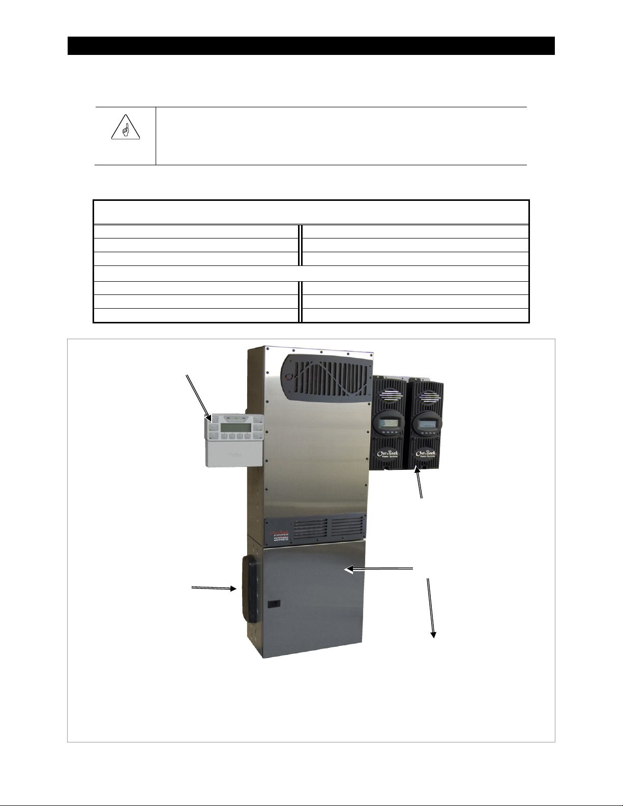
Figure 1 Radian Series Inverter/Charger.................................................................................................. 3
Figure 2 Radian Inverter and Components............................................................................................. 4
Figure 3 Applications (Example)................................................................................................................. 5
Figure 4 Bypass Switching..........................................................................................................................10
Figure 5 Bypass Switching for Multiple Inverters ...............................................................................10
Figure 6 Inverter Dimensions ....................................................................................................................11
Figure 7 System Dimensions .....................................................................................................................12
Figure 8 Installing the Mounting Plate...................................................................................................13
Figure 9 Mounting the Inverter ................................................................................................................14
Figure 10 Mounting for System Components........................................................................................15
Figure 11 Removing the Front Cover........................................................................................................16
Figure 12 DC Terminals, Ribbon Cables, and Auxiliary Terminals...................................................17
Figure 13 AC Terminals, Ports, and Ground Bus....................................................................................18
Figure 14 Chassis Ground TBB.....................................................................................................................19
Figure 15 GS7048E and GS3548E Battery Terminals............................................................................20
Figure 16 DC Cable Hardware (Radian inverter)....................................................................................21
Figure 17 AC Terminals ..................................................................................................................................22
Figure 18 AC Sources......................................................................................................................................23
Figure 19 Accessory Connections ..............................................................................................................24
Figure 20 ON/OFF Jumper and Connections..........................................................................................24
Figure 21 AUX Connections for Vent Fan (Example)............................................................................25
Figure 22 AUX Connections for Diversion (Example) ..........................................................................26
Figure 23 Two-Wire Generator Start (RELAY AUX)................................................................................27
Figure 24 Two-Wire Generator Start (12V AUX).....................................................................................27
Figure 25 Three-Wire Generator Start (Example)..................................................................................28
Figure 26 Single-Inverter AC System.........................................................................................................29
Figure 27 Single-Inverter AC Wiring with GS Load Center.................................................................30
Figure 28 OutBack Communications Manager and System Display ..............................................31
Figure 29 Example of Parallel Stacking Arrangement (Three Inverters)........................................33
Figure 30 Parallel AC System........................................................................................................................34
Figure 31 Parallel AC Wiring with GS Load Centers..............................................................................35
Figure 32 Example of Three-Phase Stacking (Three Inverters).........................................................36
Figure 33 Example of Three-Phase Stacking (Nine Inverters)...........................................................36
Figure 34 Three-Phase AC System .............................................................................................................38
Figure 35 Three-Phase AC Wiring with GS Load Centers ...................................................................39