Stevens POGO User manual

POGO Weather Station
Installation Guide
Rev. May 2019
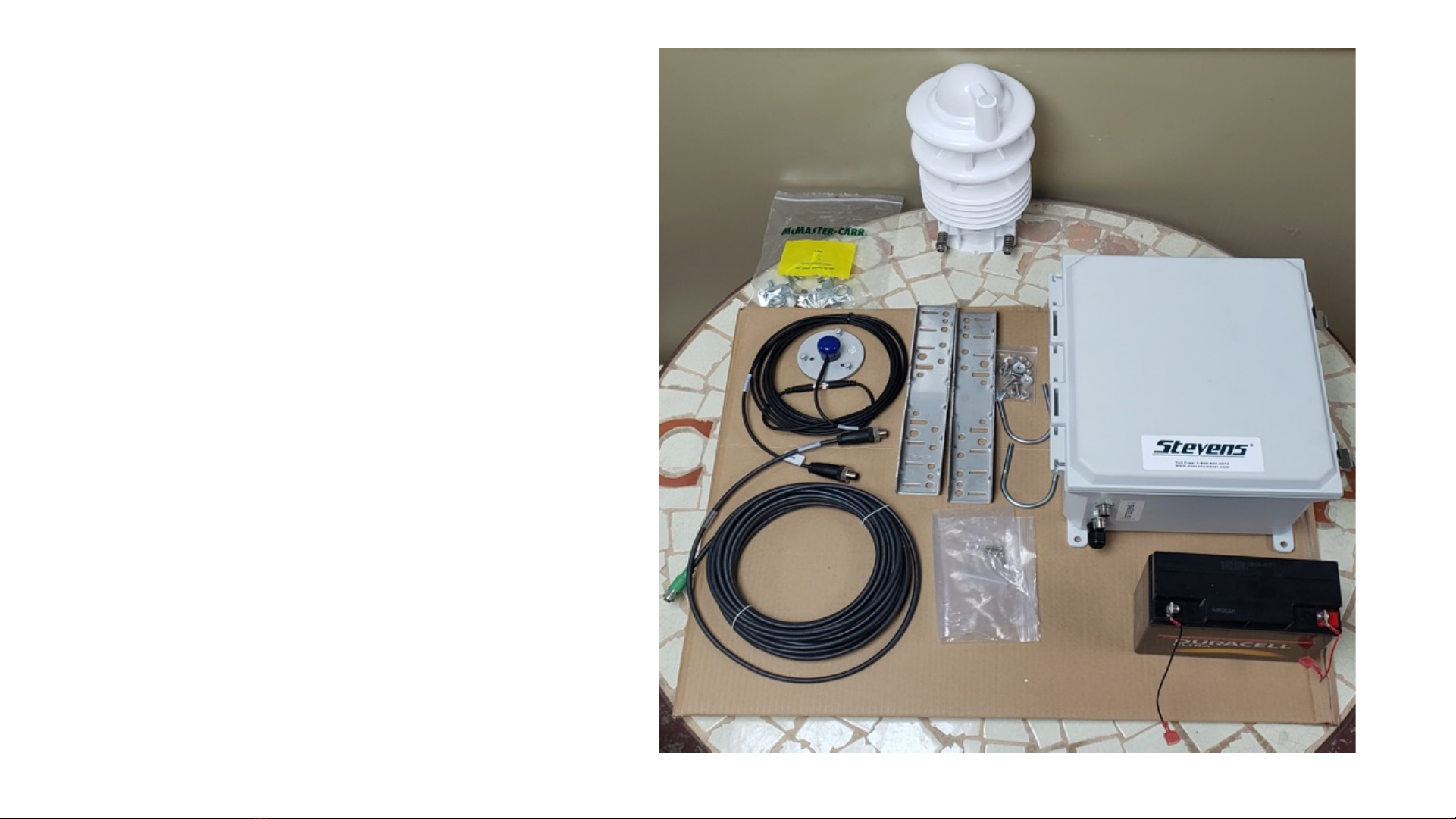
Step 1: Parts and Tools
Review parts and lay out for easy review and
assembly
1 –Power / Communication Box
2 -Power / Communication Box mounting
hardware
3 –All-in-one multi-parameter sensor
4 –All-in-one multi-variable station wire
5 –PAR sunlight sensor
6 –Rechargeable battery
7 –Tripod extension mast hardware
1
2
3
4
5
6
7
2

Step 1 (Cont.): Parts and
Tools
Tools needed:
•7/16” (11 mm) box end wrench
•½” (13 mm) box end wrench
•9/16” (14 mm) box end wrench
•Ratchets in above sizes can
replace box end for some
components to make
installation easier and faster
•2-3 mm precision flat-head
screwdriver
•#2 and #3 Philips screwdrivers
•Wire cutters
•Wire ties (as needed for
organization)
3

Step 2: Unpack Tripod
Unpack the tripod, without the extension mast and legs, so that
the connection bars are parallel with the ground.
Notes: guide wire, cement base, etc.
4

Step 3: Mount Brackets to
Power/Communication Box
1. Remove plastic extension tabs and
hardware from plastic bag.
2. Attach the extension tabs, as shown
in illustration 5-1, to the box. Leave
slightly loose to adjust and line up
holes with mounting brackets before
tightening.
3. Mount top and bottom metal
brackets, as shown in illustration 5-2.
4. Be sure you mount as shown so that
both the top and bottom bracket
have the UBolt holes visible
5

Step 4: Mount
Communication Box
to One Tripod Leg
Using hardware shown (U-bolts, nuts,
bolts, lock washers, flat washers),
mount communication box to one
tripod leg
6

Step 5: Attach Adapter for
Station to Extension Mast
On tapered end of extension mast, attach the adapter which will
be used for mounting the station to the mast
Tighten both the fitting securing the adapter to the mast and the
adapter which will be used on the station end where U-Bolts will
be attached.
Make sure the mast does not extend above the pvc fitting to not
allow the multi-variable station to seat completely.
You will have to hold one end to tighten the other completely
7

Step 6: Attach Station to Extension Mast
Using U-Bolt assembly, attached all in one multi variable station to the extension mast adapter. Attach communication wire to multi-parameter
station by lining up key and slot, clipping wire in groove on back of station and tightening securely
DO NOT OVERTIGHTEN
In this image,
notice the yellow
cap on the port
where the multi-
parameter
communication
wire will connect
Beneath this is a
groove in the
station housing to
hold the wire in
place as you
connect the wire
8
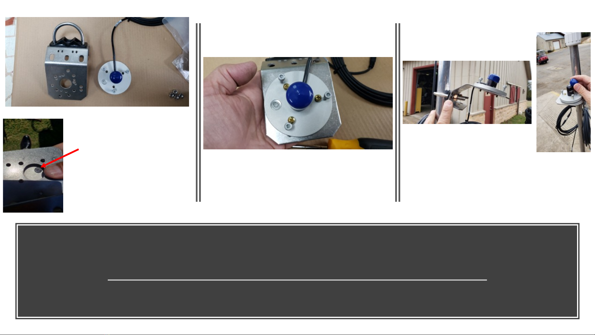
Step 7: Attach PAR Sensor to Mast
Using PAR sensor assembly parts (shown), attach PAR sensor to mast before adding mast to tripod. Mount the PAR sensor just
beneath the multi variable station with a small space between them. Note that the PAR sensor will need to face toward the sun
(example: facing south when installing north of the equator)
PAR Sensor Assembly Parts
Mount PAR sensor to PAR
sensor mounting plate
using 3 Phillips screws
Attach PAR sensor mounting plate to
extension mast. Tighten U-Bolt to
level plate securely, and remove the
sensor cap (blue in this photo)
If PAR sensor is not on
the PAR sensor plate to
be mounted on the
bracket, install the PAR
sensor using the small
black screw on the
underside of the sensor
9
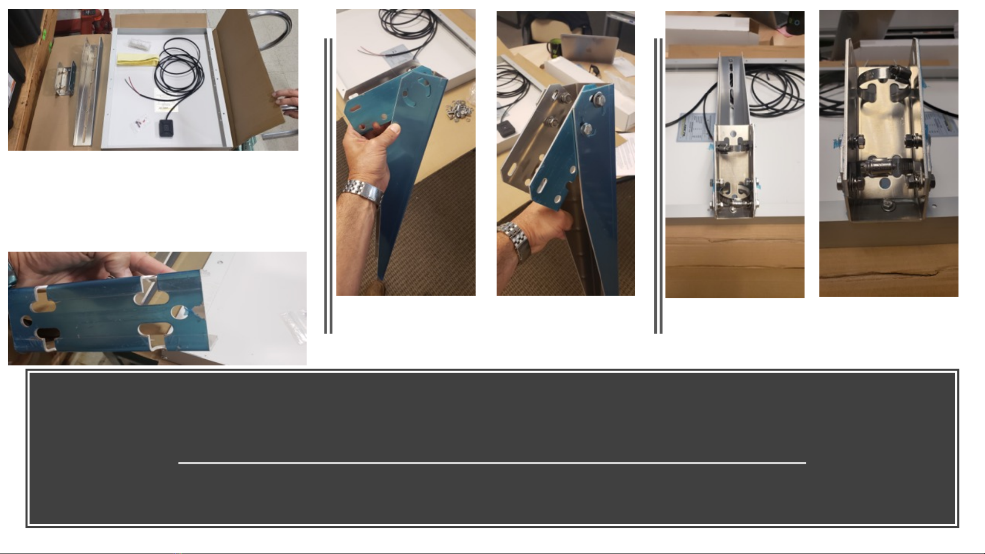
Step 9: Attach Solar Panel Bracket
Before mounting the solar panel to the tripod leg, first attach the solar panel bracket to the rear of the
solar panel and add (2) hose clamps which will be used to mount the panel to the tripod leg
Note that bracket (left) and solar
panel (right, upside down here) are
packaged separately. Peel off blue
film from brackets (below)
Line up brackets for assembly. Use
bolts, washer, washer, lock washer and
nuts to assemble
Using (2) 2.5” (6.35 cm) hose clamps,
feed clamps through holes for assembly
to tripod leg
10
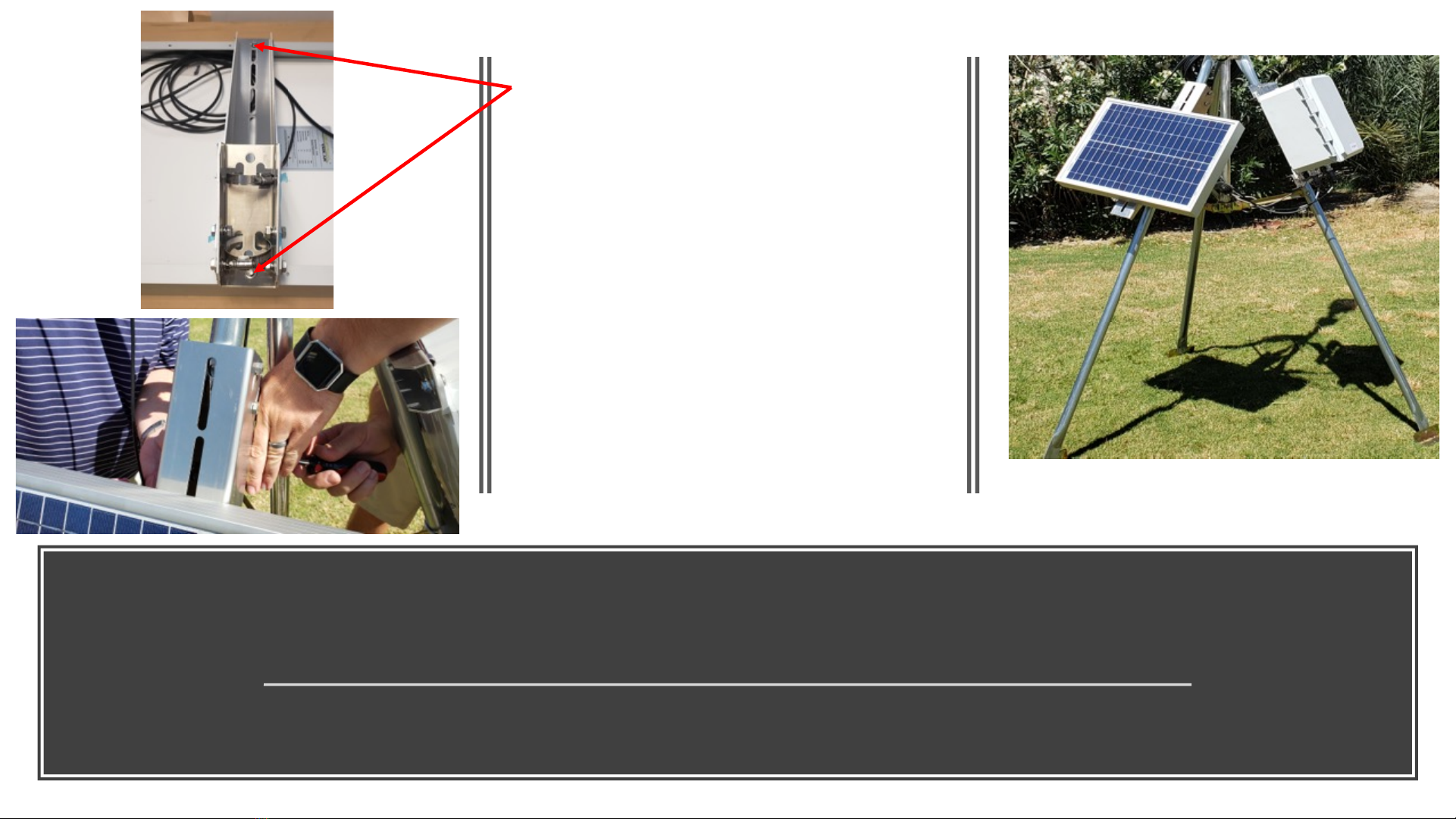
Step 10: Attach Solar Panel Assembly to Tripod Leg
First, complete bracket assembly to solar panel as illustrated. Then using hose clamps, mount solar panel assembly to the tripod
leg. IMPORTANT –Solar panel MUST face the south sky (in northern hemisphere) and north sky (in southern hemisphere)
On upper left, see how bracket is attached
to solar panel using bolts, washer, lock
washer and nut on each end after lining up
holes. Leave space on the upper bolt to
allow the bracket to swivel.
Note that the size of the solar panel varies
depending on your location. Image on the
right indicates the station assembled with
a 20 watt (smaller) panel.
NOTE: the multi parameter sensor has a
‘North’ indicator on it. This should point
north in the northern hemisphere (south in
the southern hemisphere) while the solar
panel is opposite on both applications
11
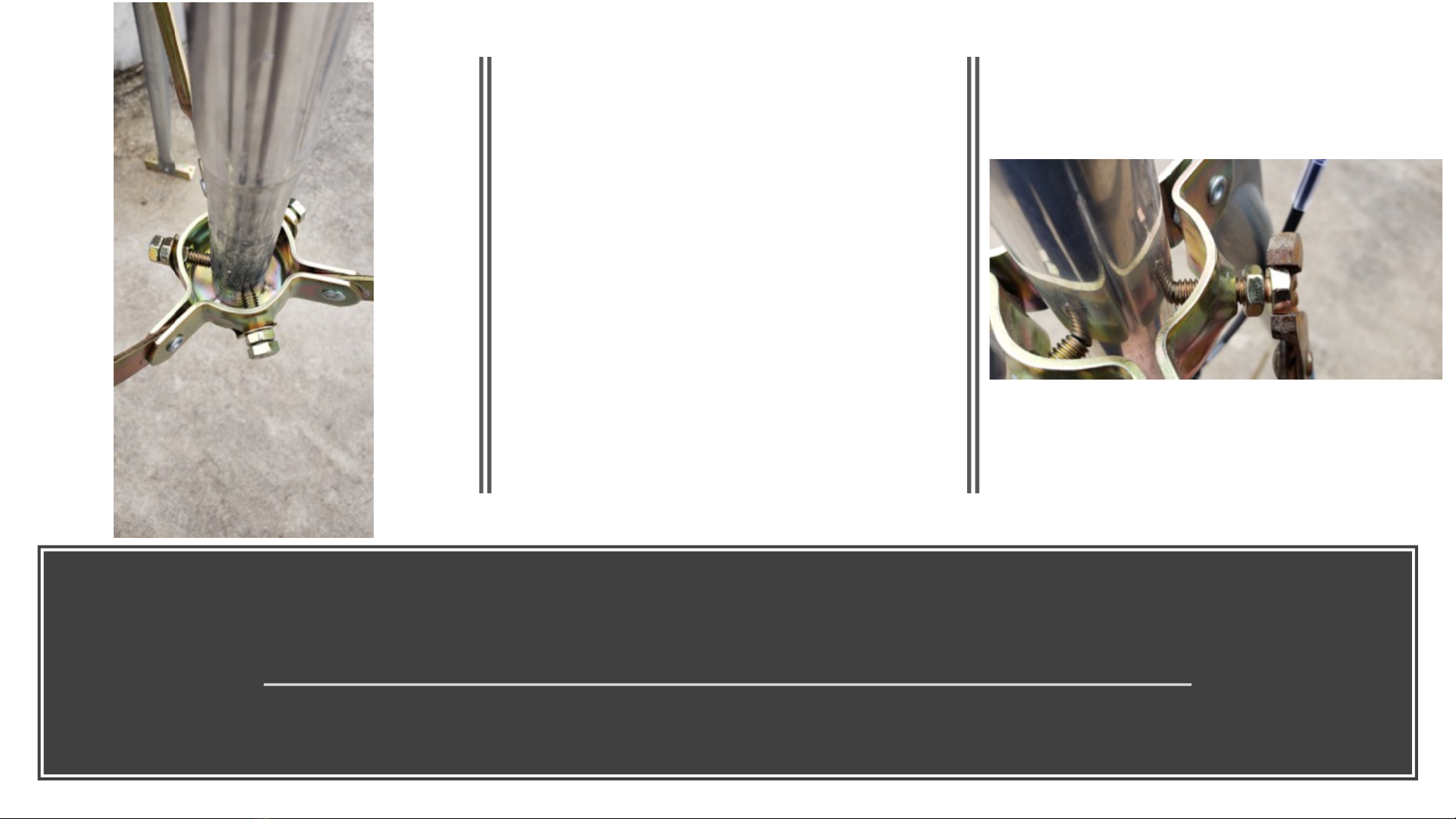
Step 11: Attach Extension Mast to Tripod
Use special hardware with locking assembly (Item 7 in parts list) to securely attach the extension mast
to the tripod
Using 2 nut system as shown on the
right, first tighten the three bolts
(outer hex end) to hold the pole level.
Then tighten down the inner nuts to
lock the bolts in place.
Note that there is an inner nut that
seats in the bracket to hold
everything in place as you tighten the
bolts down. Be careful not to allow
those nuts to fall out as you first
tighten the bolts
12

Step 12: Wiring up the Station
Be sure not to force the connections together. There is a key slot for the PAR and the Multi-parameter
station underneath the communication box while the solar panel wire is fitted to the interior connection
Connect PAR and WEATHER
connectors to the labeled connection
ports underneath the communication
box
Be sure to line up key and slot on the
connector and port for each
connection
On RIGHT, feed solar power wire
through connector port underneath
communication box. Wire up the
panel in following instructions…
Labels underneath communication box
13
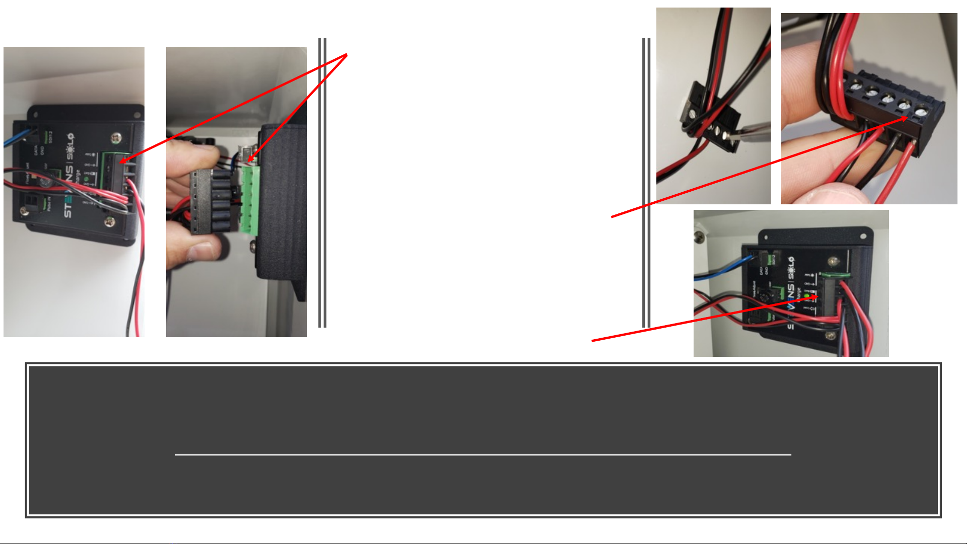
Step 12 (Cont.): Wiring up the Station
You must remove the mini connection wire assembly off of the ‘Solo’ inside the box to wire the solar
panel
Remove the mini clip (left) from the
Solo power adapter inside the
communication box. Squeeze hard
with your fingers on each end and
firmly pull back with a slight side to
side wiggle to remove the clip
Wire the black wire from the solar
panel to ‘GND’ connection and the
red wire to the ‘Solar’ connection
using a small precision flat
screwdriver to looser the screws,
insert the wire and tighten the screws
Replace the Solo mini connection clip
and make sure it is full seated
14
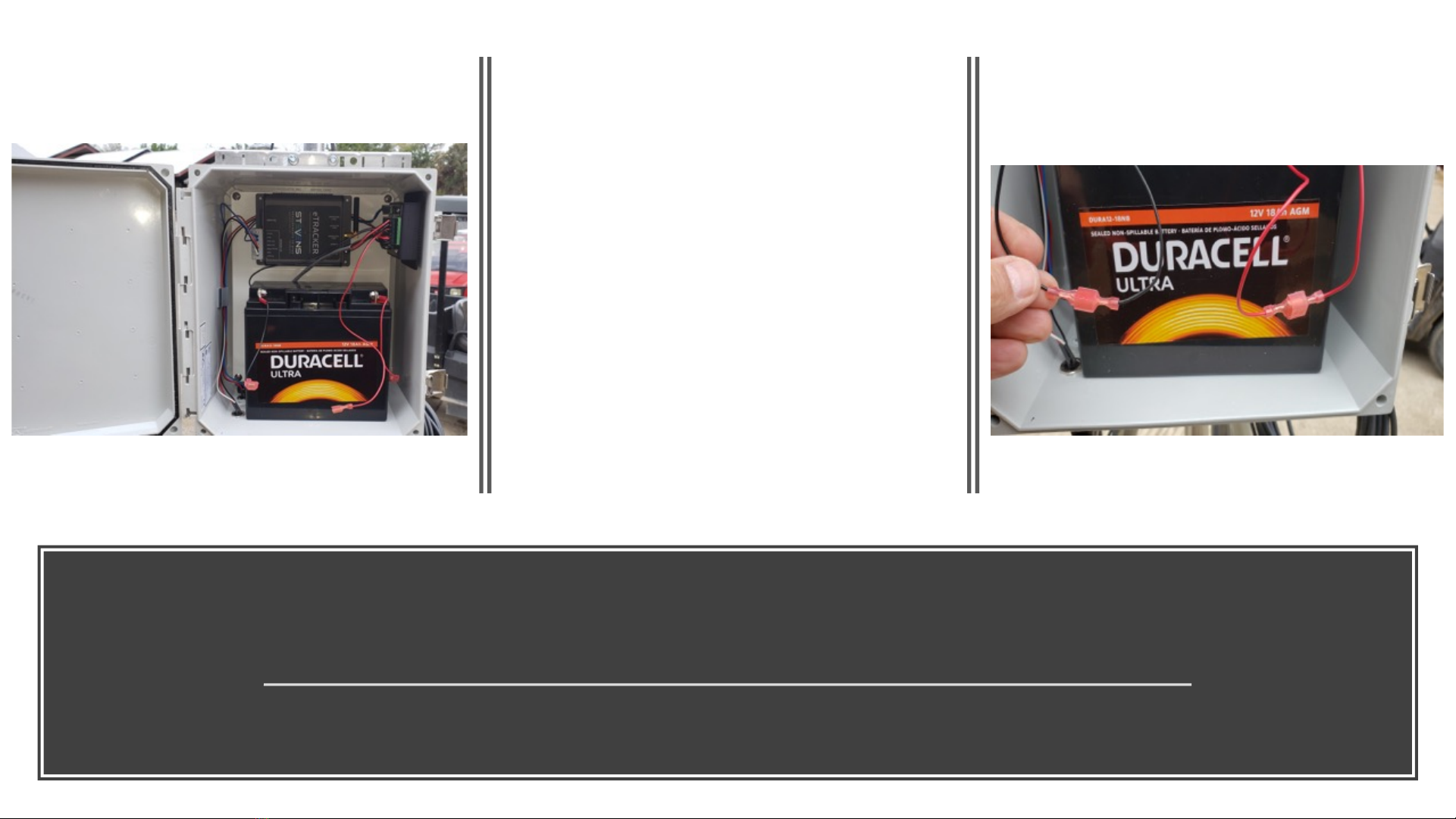
Step 12 (Cont.): Wiring up the Station
LAST STEP: Wire up the Battery!
NOTE: FOR NON-USA APPLICATIONS, PROGRAM THE APN FOR YOUR SIM CARD (SEE DETAILS) BEFORE POWERING UP YOUR STATION
Place the rechargeable battery inside the
communication box on the bottom shelf as
shown
Connect the black connector/wire to black
and red connector/wire to red
Securely close your box with the latch and
use wire ties to wrap up and secure your
wires to the tripod or mounting pole
15
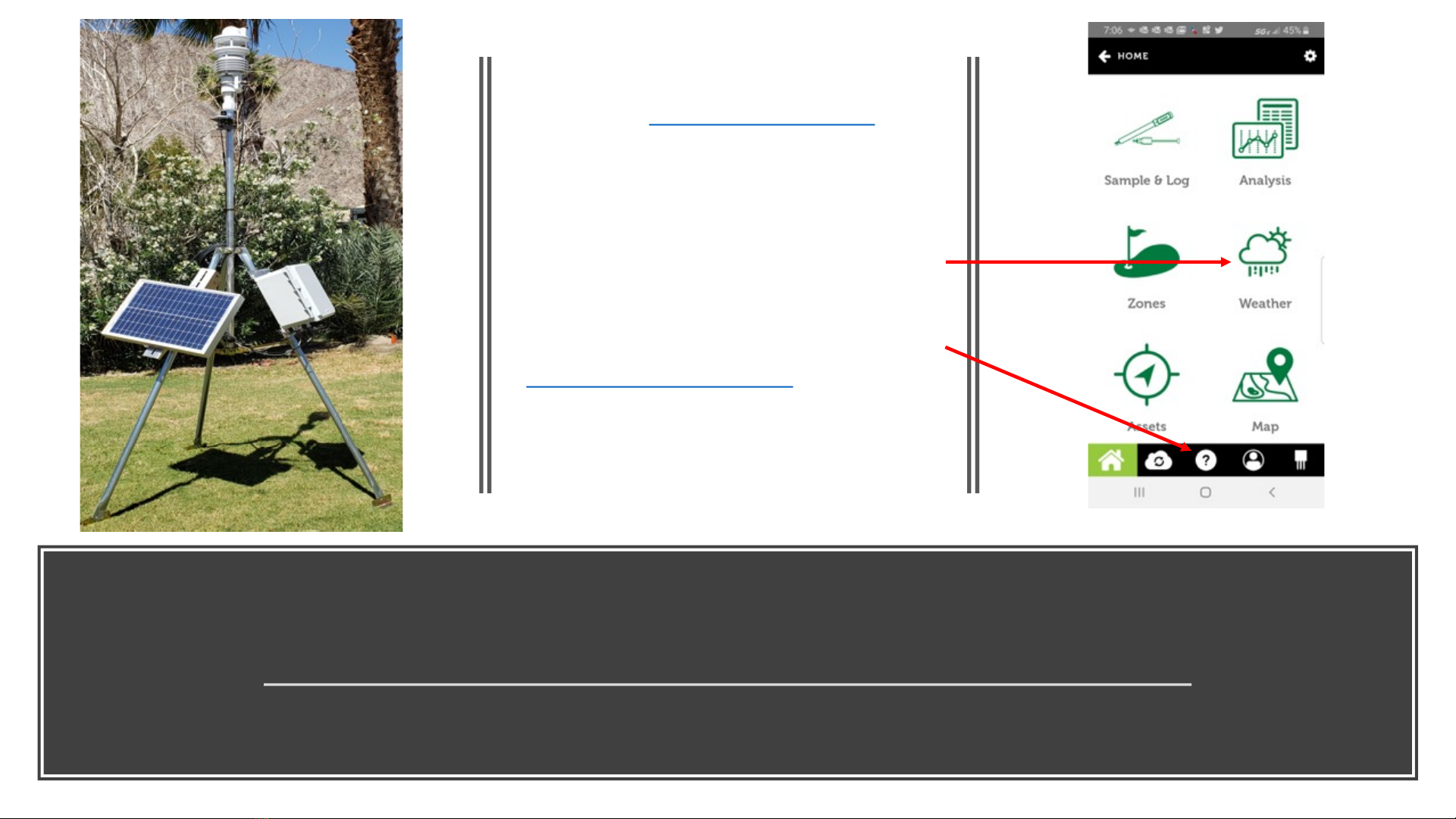
Final Step: Enjoy Your POGO Weather Analysis
www.pogoturfpro.com : Log in through the app or web to see your ‘Weather’ dashboard
NOTE: FOR NON-USA APPLICATIONS, PROGRAM THE APN FOR YOUR SIM CARD (SEE DETAILS) BEFORE POWERING UP YOUR STATION
Log in to your POGO ‘TurfPro Mobile’ or
for POGO WiFi users, ‘POGO Turf Pro’ app,
or log on at www.pogoturfpro.com and
navigate to ‘Weather’ on your account to
see your dashboard at any time
Note that weather stations are assigned to
a particular ‘Property’ on your account so
you must be logged in to the appropriate
Property to view your weather data. For
assistance at any time, contact support at
[email protected], through the
app under the Support tab (‘?’) or by
calling 1-503-445-8000
Note that it may take an hour or so
before you see your first trending data
16

Reprogramming
the SIM card
NON-USA
1. Ensure that the power is disconnected from your eTracker GSM unit.
2. Remove the Sensor Interface Box from the eTracker.
a. If it is a Mini Sensor Interface, loosen the screw that holds this box to the main
enclosure, and then disconnect it.
b. If it is the Full Sensor Interface, then unplug the ribbon cable assembly connected to
that port.
3. Remove the two screws on the antenna side at the outer edge of the end-plate
that holds the end-plate and accent-plate to the enclosure. Do not remove the
center screw.
4. Carefully slide out the PCB card from the enclosure just enough to expose the
SIM card holder on the top of the unit.
5. Pull back and up on the clip to free the SIM card that has been installed. Slide it
out of the clip and replace it with the new SIM card. Push the clip back down and
lock it in place
6. Slide the PCB card back into the enclosure and replace the screws.
7. Connect the Sensor Interface Box again.
8. Ensure the SD card destin.txt file has the correct APN for the SIM card carrier. In
the case of changing a SIM card, the APN: line will need to be changed for the
carrier being used. This can take on many formats and can also include a
Username and Password, although this is rare and often left blank.
9. Assuming good cell coverage and the connection of an antenna, repower the
unit. Your eTracker GSM will connect with the tower and server, retrieve its setup
information, apply this configuration to the unit, and begin transmitting your
data.
Example APN setup below. You will likely be
changing the APN: value which is provided by
the cellular service provider. Copy the APN
value that they give you after a space
following ‘APN:’ Your provider may or may not
require a username and password
Domain: api.stevens-connect.com
Folders: /incoming/etracker
Port #: 80
APN: 10569.mcs
Username:
Password:
OPTIONAL: FOR NON-USA APPLICATIONS
(See illustrations on following page)
17
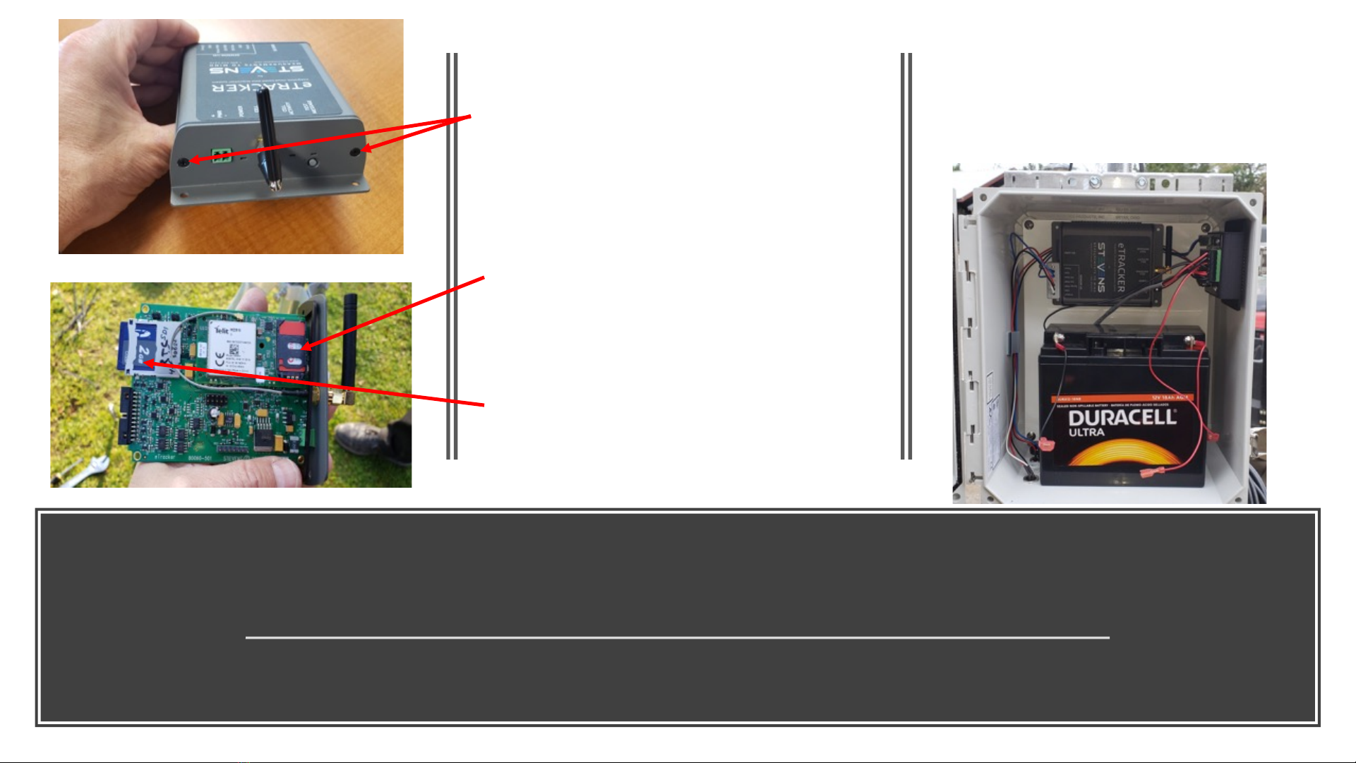
Non-USA Applications: Removing eTracker,
Programming APN on SD Card, Inserting SIM
To install standard size SIM, you must remove
the cover to the eTracker. Do so by removing
the 2 Philips screws on the antenna side of
the eTracker and pulling the board outward
away from the housing gently
To install the SIM, unlock the SIM clamp by
sliding forward and lifting up. Once SIM is
inserted, fully seat clip and slide back to lock
it in place
To program the APN on the SD Card, remove
the SD Card by pressing in from the outer
edge and it will pop out, plug into a PC
enabled with an SD Card reader and follow
the instructions for programming (previous
page). Reinsert the SD Card by pushing all the
way in until it clips in place
18
To remove the eTracker, grab it securely and pull it from
the box wall. It is secured with industrial strength
Velcro. Once detached, you can disconnect the power
connector on the right side beneath the antenna and
remove the sensor interface box on the left side as
described in the previous page instructions
Popular Weather Station manuals by other brands


La Crosse Technology
La Crosse Technology C86234 Faqs

Topcon
Topcon A3280 Operation & installation manual

Heitronic
Heitronic 49540 Installation and operating instructions

Oregon Scientific
Oregon Scientific WMR86 user manual

DAVIS
DAVIS Vantage Connect user manual

Hama
Hama 00092659 EWS-165 operating instructions

La Crosse Technology
La Crosse Technology WS-7013U-IT instruction manual

La Crosse Technology
La Crosse Technology WS-7168U instruction manual

Froggit
Froggit WH2800 user manual

Columbia Weather Systems
Columbia Weather Systems CAPRICORN II PLUS user manual

Ambient Weather
Ambient Weather WS-1173 user manual

Oregon Scientific
Oregon Scientific BAR826HG user manual