Stewart Filmscreen VCS-1007 User manual
TO THE INSTALLER:BE SURE TO LEAVE THIS MANUAL WITH THE OWNER.
VCS-1007
Video Conference Screen
To the Owner
Installation Instructions
Operating the Screen
Maintenance
OWNER’S MANUAL

Printed in U.S.A.
©2007 Stewart Filmscreen Corporation
Stewart Filmscreen reserves the right to make changes to the product specified in this document.
From time to time, this document is updated. Current versions of documentation are posted on the Stewart Filmscreen website at
www.stewartfilm.com.

Contents
To the Owner . . . . . . . . . . . . . . . . . . . . . . . . . . . . . . . . . . . . . . 2
Receiving and Removal from Shipping Crate . . . . . . . . . . . . . 3
Preparing the Installation . . . . . . . . . . . . . . . . . . . . . . . . . . . . . 4
Step 1. Hanging the Case . . . . . . . . . . . . . . . . . . . . . . . . . . . . 5
Step 2. Electrical Connection . . . . . . . . . . . . . . . . . . . . . . . . . . 6
Operating the Screen . . . . . . . . . . . . . . . . . . . . . . . . . . . . . . . 8
Adjusting the Screen Extension . . . . . . . . . . . . . . . . . . . . . . . . 9
Screen Care and Cleaning . . . . . . . . . . . . . . . . . . . . . . . . . . 10
Troubleshooting . . . . . . . . . . . . . . . . . . . . . . . . . . . . . . . . . . . .11
Product Warranty . . . . . . . . . . . . . . . . . . . . . . . . . . . . . . . . . . 12
Video Conference Screen: Owner’s Manual 1
Video Conference Screen
OWNER’S MANUAL

Congratulations on your purchase of the finest optical viewing screen
available anywhere in the world!
Please take a moment to review this manual, it will help ensure you many
years of trouble-free service from your new Stewart Filmscreen product.
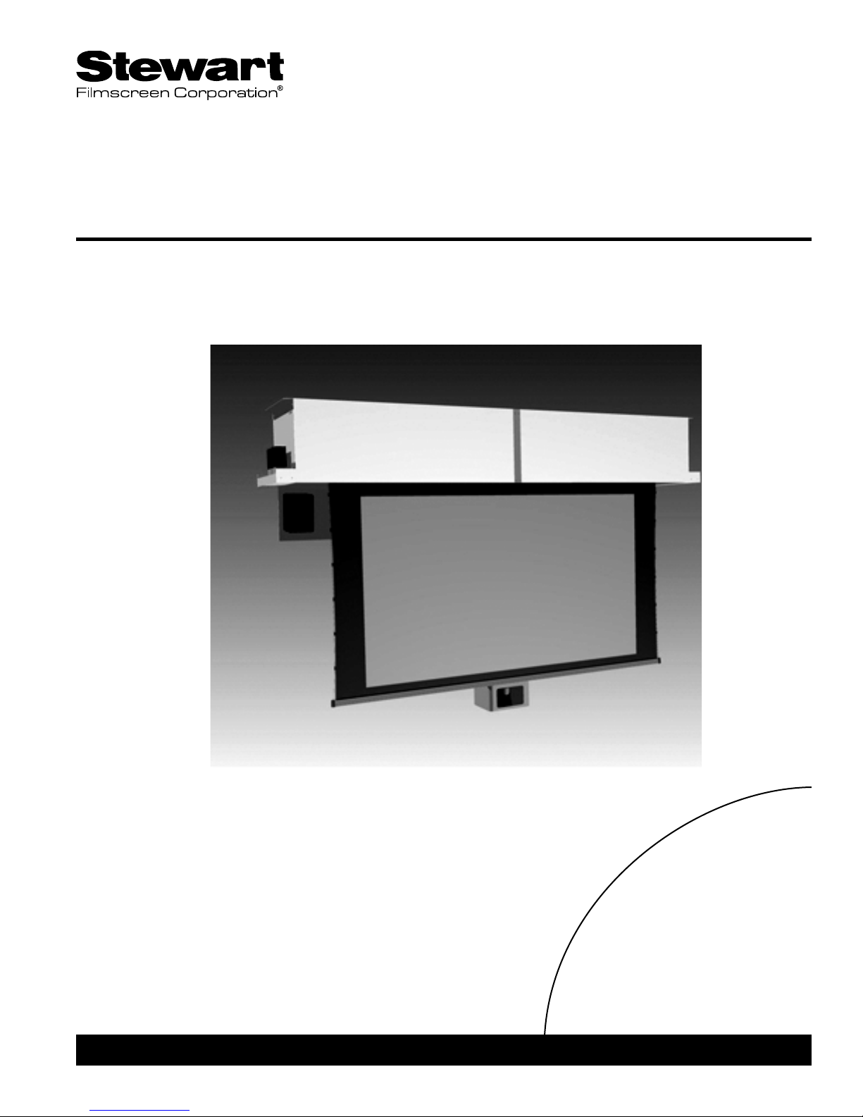
About the Video Conference Screen
The Video Conference Screen housing consists of an automated electric
door, electric retractable projection screen, and electrically operated camera
pod. The system has been designed with sequential electrical operation.
The door opens, the projection screen deploys followed by the camera pod.
The door will never close on the screen or camera pod when they are
deployed. The screen and camera pod can never be deployed while the
door is closed.
Electrical input and switch connections are located in junction boxes on the
left end and camera and (optional) speaker connectors are on the right end.
In some cases, to enable proper alignment of the displayed image on the
screen, you may need to adjust the extension of the screen and camera
pod. Follow the instructions in the section "Adjusting the Screen Extension"
should changes to the factory settings become necessary.
Do not randomly start turning any of the motor's limit switches as damage
will occur to the components and the electrical sequential operation will be
jeopardized.
Due to the nature of the materials and construction, the unit's housing is
somewhat flexible. Pay attention to this during installation as to avoid case
twisting and front to back compression.
2Stewart Filmscreen Corporation
TO THE OWNER

The Video Conference Screen is large and heavy and requires special
attention relating to shipping and transportation. Keep the following
information in mind when moving the crate from the truck to the final
mounting location.
The shipping crate needs to remain flat at all times.
The top of the crate needs to be kept up towards the sky.
Never rotate the shipping crate onto its side.
Never stand the crate on end.
Before removing the unit from the crate, review the installation instructions
and ensure that the site is prepared. To remove the unit from the shipping
crate:
1. Place the crate under the intended mounting location.
2. Remove crate lid.
3. Use appropriate methods to raise unit to mounting location.
Preferred methods are automatic winches or hydraulic lifts.
Video Conference Screen: Owner’s Manual 3
RECEIVING AND REMOVAL FROM SHIPPING CRATE

Preparation
Specifications regarding the individual screen dimensions, weight, and
controls are provided by the factory when the unit is ordered. Before
beginning the installation:
Check the specifications for the type of switch control to be used.
Ensure that the mounting area and electrical connection are
prepared.
Check the size and weight of the screen to be installed so that
you can plan for the number of people required for the mounting
procedure. You need at least three people to mount the smaller
screens; more are needed for larger, heavier screens.
You will need:
Enough ladders for the personnel supporting the screen during
the mounting process
A level
Fasteners appropriate for the surface on which the screen is
being mounted
A 5/32” (4 mm) hex ball driver or Allen key
Unpacking
If there is a piece of paper protruding from the screenroll, do not remove it.
This paper will fall out as the screen is first deployed. (Some screens will not
require this paper.) You will remove the screen lock-down brackets after you
make the electrical connection; when the door is first opened it is stopped
and the screen deploys. Refer to the information in "Operating the System."
4Stewart Filmscreen Corporation
PREPARING THE INSTALLATION
Before proceeding with the installation of this screen,
take time to thoroughly read and understand these
installation and operation instructions.
All electrical wiring installations must conform to local
and national codes and should be performed by
qualified service personnel.
There are no user-serviceable parts contained within
the unit.
Caution
During installation, do not place the unit on an unstable
cart, stand, table, or ladder. The unit may fall, causing injury
to a child or adult and damage to the unit.

Video Conference Screen: Owner’s Manual 5
STEP 1. HANGING THE CASE
Professional mounting techniques should be used. Stewart Filmscreen
Corporation cannot be liable for substandard or faulty installations.
Make sure that you mount the screen so that the electrical box is on the left
side (audience left).
The Video Conference Screen is fully assembled and ready to install into
the ceiling or soffit. A false ceiling is not intended to support the weight of
this product. The unit can be bolted directly to the support structure or
suspended. Chain or threaded rod is typically used for suspended type
installations. If the unit is to be mounted to plaster, masonry or other type of
surface, use appropriate fasteners. Always use high grade / rated hardware.
1. Mount the housing via the mounting brackets located on the top
ends.
- Use the drilled holes on these ends for the specified mounting
hardware.
- Use appropriate attachment hardware to secure the housing. Use
case hardened or rated fasteners.
2. Install the unit onto the support structure making sure that the
bottom of the case is flush with the finished ceiling plane.
- Avoid case torque or twisting as operational difficulties will ensue.
- Do not compress the front to back with ceiling treatment as this too
will cause improper door operation.
3. Use a carpenter's level to make sure the housing is level end to
end as well as front to back. After mounting, check the door to
make sure it is flush to the box at both ends and that there is
proper clearance around its entire perimeter. Readjust mounting if
required at this time.
4. Drywall or other ceiling material may be run flush to the housing.
It is essential not to "compress" the housing front to back with any
ceiling treatment or tiles as this will cause faulty door operation.

6Stewart Filmscreen Corporation
The motor requires standard AC input (unless an alternate voltage has been
specified).
This manual includes instructions for LVC (low voltage control) switch. If
your systems uses another type, be sure you know how to make the
connections. Contact the factory as needed.
General suggestions for wiring:
Soldering is recommended.
The use of wire nuts is acceptable.
Preparation—Removing access panel
All connections are made to the electrical box on the side of the unit
(audience left). An access panel covers the electrical connections. To
remove the access panel on the underside of the unit, remove the two hex
screws. Replace the access panel after the electrical connections have been
made.
High voltage AC input connection
We advise this connection be done by a qualified AV technician or
electrician. Stewart Filmscreen Corp. cannot be held liable for faulty or
substandard connections.
Connect the AC input line to the electrical junction box located on the left
end of the housing. You will make three connections:
White is neutral.
Black is hot.
Green is ground.
Use 3 conductor 16 ga minimum romex or service cord for hookup. Wire
nuts can be used for the connections.
STEP 2. ELECTRICAL CONNECTION
Caution
Professional techniques should be used when making any
electrical connection. A qualified electrician should perform
these procedures.
Be sure to follow all standard safety procedures for
installing electrical devices.
Do not disassemble or alter the configuration of the motor
or the unit's electrical connections. This may cause injury to
you or damage to the product and will void the product
warranty.
The electrical connection should be made only to the type
of power source indicated on the marking label.

Low Voltage Control with 3-button momentary wall switch
(standard control)
A standard Low Voltage Control is sequentially tied to each motor. A 3-
button momentary switch can be connected to the switching input terminals.
Use 20 - 24 ga. 4-conductor electronic communication wire to connect to the
switch input wire located in the switch connection junction box.
The color connections are:
White is common.
Red is up.
Black is down.
Yellow is stop.
A parallel connection to this switching input can also be made to other
associated A/V switching networks. Any additional switches connected here
must be "momentary" type.
Once the connections have been made a "Down" command will open the
door. Once the door has opened, the projection screen will deploy. Upon
deployment of the projection screen the video camera pod will deploy. When
an "Up" command is given, the camera pod will retract. At that time the
projection screen will retract followed by the closing of the door.
Camera connection box and optional speaker connector
The video camera connection box is located on the right end plate of the
housing. An optional speaker terminal connector block is also in this
location. If you have optional speakers included, they are connected here.
Video Conference Screen: Owner’s Manual 7
The factory has secured the screen and camera pod for transportation.
Follow the "First time activation" instructions to ensure any packing products
and/or system lockdown brackets are completely removed when the door is
first opened, before deployment of the screen and camera pod.
First time activation
1. Open the door to approximately 90 degrees and press "Stop."
2. At this time it is imperative that you remove any screen lockdown
brackets and/or foam retention blocks. Do not allow the unit to
cycle further until you remove all shipping protection materials.
3. Press "Down," the door kicks back slightly and the projection
screen deploys. The first time you operate the screen, the
protective paper falls out as the screen unrolls. Once the screen
is fully deployed, make sure that no packing paper remains on the
screenroll. The screen can be damaged if loose paper or shipping
materials remain.
4. When the screen reaches its fully deployed position, the camera
pod automatically deploys. This system is electrically sequenced
so you do not have individual control of the motors.
General operation
To lower the screen and camera pod, press the Down button. The door
opens, the screen lowers, and then the camera pod lowers. If you want to
use the screen without the camera pod, press the Stop button after the
screen deploys, but before the camera pod lowers.
To retract the screen and camera pod, press the Up button. The camera
pod raises, followed by the screen. Finally the door closes.
When you lower or retract the screen, it will stop at its factory preset limit. If
an obstacle (such as a person or furniture) gets in the path of the screen as
it is lowered, you should use the switch control to stop the screen's motion;
it will not automatically stop if it hits an obstacle.
In general, when the screen is not in use, store it in the fully retracted
position.
8Stewart Filmscreen Corporation
OPERATING THE SCREEN
Caution
Stop the door before
the screen deploys.
Caution
Do not operate the motor(s) when any of the following
occurs:
The unit emits any smoke, heat, abnormal noise or
unusual electrical type odor.
The unit is damaged in some way, such as damage
from a water leak.
Obstructions are permitting correct deployment of
door, screen or camera pod.
If any of these situations occur, remove obstructions and /
or call a qualified service person if required.
The extension and retraction limit switches have been preset at the factory.
In general, we advise you to avoid readjusting these switches.
In some cases, to enable proper alignment of the displayed image on the
screen, you may need to adjust the extension of the screen or the mask. If
adjustment to the extension is necessary, carefully follow these instructions.
Modifying the screen extension
You can increase the extension of the screen and mask up to 3" / 7.6 cm
past the factory preset stop, or you can decrease the extension by
approximately 4" (10 cm) from the factory preset stop. Do not attempt to
modify the screen extension beyond these recommended amounts.
Improper adjustments to the screen's deployment setting will cause screen
problems.
The limit switches are located on the left side of the screen roller tube inside
the housing.
To increase the screen's fully extended (screen down) stop position:
1. Lower the screen to its current stop position.
2. Locate the white "Down" extension limit located on the motor's
head, left side of the screen tube. Use an electrician style
screwdriver or 4 mm hex key to turn this switch in a counter-
clockwise direction. If the power is applied to the motor, the
screen will drop incrementally as the switch is turned.
Note: One complete turn of the switch will make approximately a
1" (2.5 cm) change in the screen stop position.
To decrease the screen extension:
1. Lower the screen until it is extended about halfway down and
then press "Stop."
2. Locate the white "Down" extension limit switch located on the left
side of the screen tube. Use an electrician style screwdriver or 4
mm hex key to turn the switch in a clockwise direction.
Note: One complete turn of the switch will make approximately a
1" (2.5 cm) change in the screen stop position.
3. Activate the screen in the down direction until it reaches the
newly reduced stop position. Repeat this procedure until the
desired stop position is reached.
Once you have made the adjustment, whenever you lower the screen, it will
automatically stop at the new position.
Note: It is recommended that you make a note of any changes made to the
factory preset.
Video Conference Screen: Owner’s Manual 9
ADJUSTING THE SCREEN EXTENSION
Caution
Improper adjustment of
any of the motor's limit
switches can cause
irreparable damage to
the screen and related
components, resulting
in voiding the factory
warranty.
Caution
The screen is fully
retracted when the
batten stops just inside
the bottom of the
housing. Do not
attempt adjustments
with the "yellow" (UP)
retraction limit switch
that will further retract
the screen. Incorrect
adjustment of the
switch will cause
severe and permanent
screen damage. This
switch also controls the
signal for the door
closure. Improper
adjustment could cause
the door to close
prematurely on the
screen. Consult the
factory if you have any
questions.

With reasonable care, you may expect many years of trouble-free use of
your Stewart Video Conference Screen.
We encourage you to keep your screen clean. To protect your screen when
it is not in use, store it in the fully retracted position.
Avoid getting any foreign material on the screen, as cleaning may prove
very difficult. It may not be possible to remove scratches, paint, ink, etc.
General maintenance
The screen surface is delicate. Special attention to these instructions
should be followed when cleaning.
A draftsman-style brush may be used to lightly whisk away any
loose dirt or dust particles. (This type of brush can be found in
office supply stores).
Newer style soft synthetic dusting wands can also be used to
lightly whisk away any loose dirt or dust particles.
For tougher spots, use a mild solution detergent, water, and a
sponge. Rub lightly. Blot with a damp sponge to absorb excess
water. Do not try to dry off residual watermarks as they will
evaporate in a few minutes.
Aggressive or abrasive cleaning action will deteriorate the
screen's optical quality.
Never use solvents, abrasives, chemicals or any other substances
to clean the screen.
Replacement parts and service
No user-serviceable parts are contained within the unit. Contact you dealer
or the factory if you require part replacement or service.
10 Stewart Filmscreen Corporation
SCREEN CARE AND CLEANING
Video Conference Screen: Owner’s Manual 11
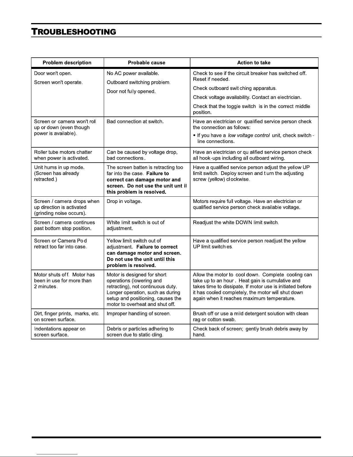
Problem description Probable cause Action to take
Door won't open.
Screen won't operate.
No AC power available.
Outboard switching problem.
Door not fully opened.
Check to see if the circuit breaker has switched off.
Reset if needed.
Check outboard switching apparatus.
Check voltage availability. Contact an electrician.
Check that the toggle switch is in the correct middle
position.
Screen or camera won't roll
up or down (even though
power is available).
Bad connection at switch. Have an electrician or qualified service person check
the connection as follows:
〈If you have a low voltage control unit, check switch-
line connections.
Have an electrician or qualified service person check
all hook-ups including all outboard wiring.
Have a qualified service person adjust the yellow UP
limit switch. Deploy screen and turn the adjusting
screw (yellow) clockwise.
Motors require full voltage. Have an electrician or
qualified service person check available voltage.
Readjust the white DOWN limit switch.
Have a qualified service person readjust the yellow
UP limit switches.
Allow the motor to cool down. Complete cooling can
take up to an hour. Heat gain is cumulative and
takes time to dissipate. If motor use is initiated before
it has cooled completely, the motor will shut down
again when it reaches maximum temperature.
Brush off or use a mild detergent solution with clean
rag or cotton swab.
Check back of screen; gently brush debris away by
hand.

LIMITED ONE YEAR WARRANTY ON STEWART FILMSCREEN CORP
PROJECTION SCREENS SYSTEM
STEWART FILMSCREEN CORPORATION (Stewart) warrants its screens to
the original purchaser only, to be free from defects in materials and
workmanship for a period of one (1) year from the date of purchase by the
original purchaser provided they are properly operated and maintained
according to Stewart instructions and are not damaged due to improper
handling or treatment after shipment from the factory.
This warranty does not apply to equipment showing evidence of misuse,
abuse, or accidental damage, or which has been tampered with or repaired
by person other than authorized Stewart personnel.
Stewart's sole obligation under this warranty shall be to repair or to replace
(at Stewart's discretion) the defective part of the merchandise. This warranty
expressly does not cover any costs of removal, installation, framing, or other
costs incident to replacing the screen or returning it to Stewart. Returns for
service should be made to your Stewart dealer. If it is necessary for the
dealer to return the screen or part to Stewart, transportation expenses to
and from Stewart are payable by the purchaser and Stewart is not
responsible for damage in shipment. To protect yourself against damage or
loss in transit, insure the product and prepay all transportation expenses.
This warranty is in lieu of all other warranties, expressed or implied,
including warranties as to fitness for use and merchantability. Any implied
warranties of fitness for use, or merchantability, that may be mandated by
statue or rule of law are limited to the one (1) year warranty period. This
warranty gives you specific legal rights, and you may also have other rights
which vary from state-to-state. In no event will Stewart be liable for sums in
excess of the purchase price of the product. No liability is assumed by
Stewart for expenses or damages resulting from interruption in operation of
equipment, or for incidental, direct, or consequential damages of any nature.
In the event that there is a defect in materials or workmanship of a Stewart
Screen, you may contact our Customer Service Department at 1161 W
Sepulveda Blvd, Torrance, California 90502-2797 (310-784-5300) Toll free
(800-762-4999).
IMPORTANT: This warranty shall not be valid and Stewart shall not be
bound by this warranty if the product is not operated and maintained in
accordance with Stewart's written instructions.
12 Stewart Filmscreen Corporation
PRODUCT WARRANTY

MAINTENANCE NOTES

www.stewartfilm.com
1-800-762-4999 Fax (310) 326-6870
Table of contents


