StewMac 65 P-REVERB User manual

ASSEMBLY INSTRUCTIONS
With loads of
helpful tips!
’65 P-REVERB 15W
COMBO AMP KIT
ORIGINAL AA1164 CIRCUIT
Sparkling bright,
perfect for the surf.

stewmac.com 2 © 2018 StewMac
Contents
About this iconic amp ............................................ 1
...................................................
2
Parts list ........................................................... 3
Tools and supplies ................................................ 5
Amp voltages are seriously dangerous! .......................... 6
How to use a snuffer stick ........................................ 6
How to read resistor values ...................................... 7
Capacitor values .................................................. 7
Prepping the cabinet ............................................. 8
Prepping the eyelet boards ..................................... 10
Tips for great soldering ......................................... 11
Installing the chassis-mounted components ................... 13
Wrapping parts onto the bias board ............................ 21
Wrapping parts onto the main board ........................... 23
Installing and soldering the boards ............................. 33
Installing the fuse, lamp, and knobs ............................ 42
Testing and troubleshooting .................................... 43
Final assembly ................................................... 45
Tips for using this amp .......................................... 45
Learning more: secrets revealed in the schematic .............. 46
AA1164 circuit schematic ........................................ 47
More iconic amp kits from StewMac . . . . . . . . . . . . . . . . . . . . . . . . . . . . . 48
AA1164 wiring diagram .......................................... 50
Tube replacement chart ......................................... 51
COPYRIGHT WARNING
This material is protected by copyright and has been created by and solely for the purposes of StewMac.
You may not sell, alter or further reproduce any part of this material, or distribute it to any other per-
son. Where provided to you in electronic format, you may only print from it for your own private use.
Failure to comply with the terms of this warning exposes you to legal action for copyright infringement.
How to build this kit!

stewmac.com 1 © 2018 StewMac
Iconic American tone
is now in your hands
Be excited!
Your new StewMac ’65 P-Reverb will be a blast
to play through and even more fun to build.
Plug your single-coils straight in and use its
signature clean tone, or go surfing with the
onboard effects.
This amp is an ICON
The smallest member of the black-panel family to offer both reverb
and tremolo, this amp made its name as a jangly pop dream machine.
Aficionados treasure its early low-end breakup powered by a pair of 6V6
power tubes.
Suggested listening while you build this kit: the Beach Boys’ “Surfin’ USA”
and the great sounds of Ryan Adams.
StewMac ICON KITS bring classics that are no longer made, or are simply
unaffordable, within reach. And the best part is you get to build them
with your own hands.
We give painstaking attention to parts selection, authentic materials, and
instantly recognizable details—everything that makes the originals so
sought after.
Build it with StewMac
These immersive instructions walk you through every step of creating
your pint-sized prince of rock-n-roll. And you’ll learn a lot, gaining a deep
knowledge of your amp’s inner workings.
Follow our steps closely for safety, too: we’ve carefully laid out a path that
even newcomers can follow in handling electrical components.
Building an amp can seem daunting, but nobody makes it easier than
StewMac. Watch for helpful tips along the way, too—we’re here to help!
Let’s get building!
’65 P-REVERB 15W
COMBO AMP KIT ORIGINAL AA1164 CIRCUIT
stewmac.com 2 © 2018 StewMac
Here’s how to build this amp!
See page
20
Wiring goes like this:
1. First, you’ll wrap the leads, connecting them without solder.
2. Then double-check all the connections. Don’t rush!
3. When everything checks out, it's time to solder.
The numbered steps tell you when.
Get the cabinet ready,
starting at Step
1
on page
8
.
You’ll prep the metal chassis
and the eyelet board too.
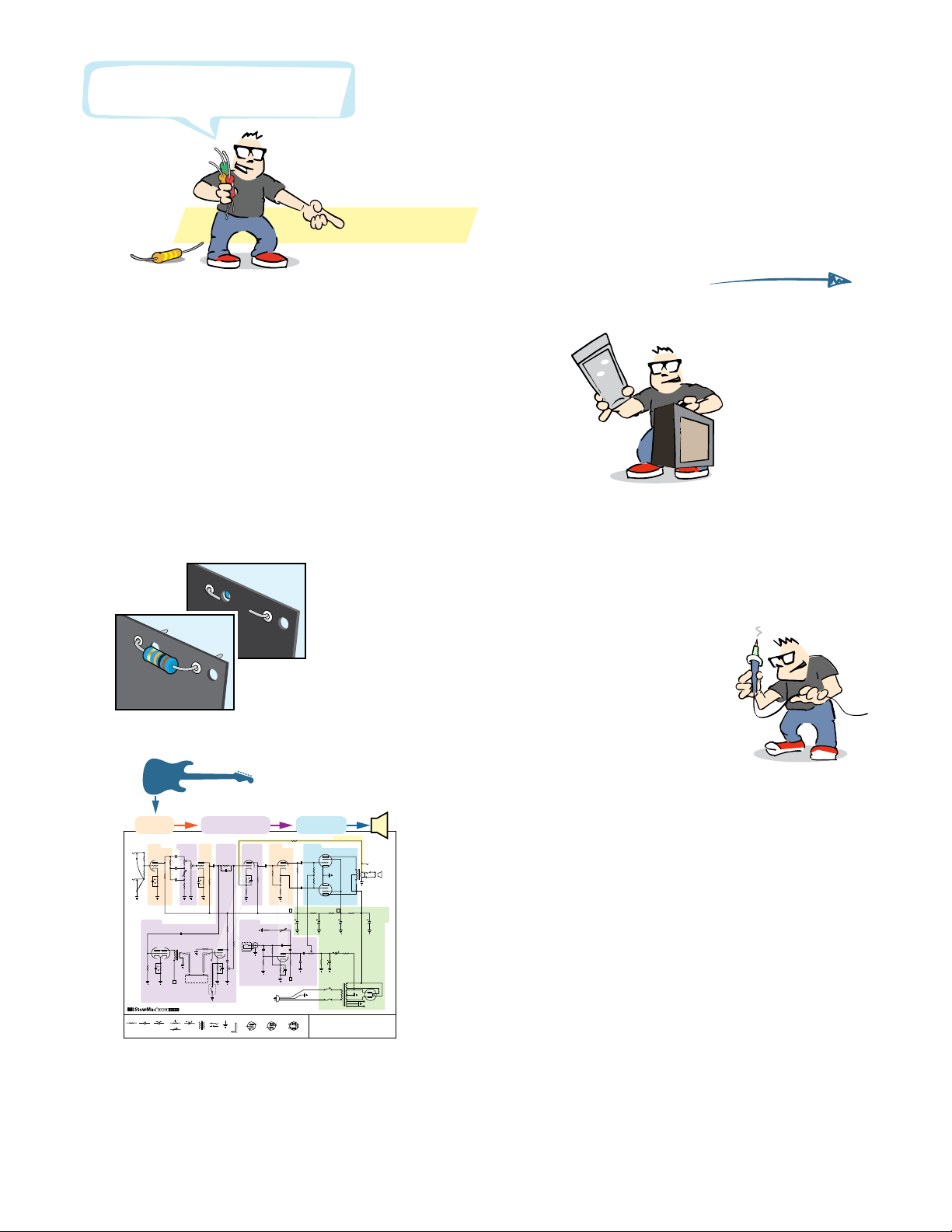
Learn more:
You don’t need to read the schematic, but it’s fun!
See how your guitar’s signal gets processed into sound
on page 46.
Sort your components by type, using the parts list.
Quick look:
#10734 © 2018 StewMac
’65 P-REVERB 15W
ORIGINAL AA1 164 CIRCUIT
GroundJackTransformer Preamp tube
plate
grid
cathode
Power tube
grid
plate
cathode
screen
Capacitor Electrolytic Cap. Diode
Resistor Potentiometers Rectifier tube
plate cathode
filament
plate
Shielded
cable
Gain GainGainProcessing Processing
ProcessingProcessing
Output
Power
Processing
Negative Feedback
68K
250KA250KA
25μF 50V
25μF 50V
25μF 50V
25μF 50V
1.5K
100K
68K
1
M
40μF
500V
20μF
500V
20μF
500V
20μF
500V
B
B
D B
.1μF
22K
100μF
100V
2
2
1
+160V
+160V
6
3
+1.3V8
+1.3V
+160V
6
8
+1.2V
+200V
6
8
+50V
7
25μF 50V
25μF 50V
1.5K
1.5K
100K
250pF
+240V+240V
100K
3MRA
Speed
+320V
Vibrato
pedal
Reverb
pedal
Reverb
100KL
Reverb unit
OutputInput
15K-2W15K-2W
1K-1W
.1μF
.022μF .022μF
SOCKETV1
7025
SOCKETV2
12AT7
SOCKETV7
GZ34
SOCKETV6
6V6 GT
SOCKETV4
12AX7
SOCKETV5
6V6 GT
SOCKETV3
12AX7 .1μF
.1μF
.01μF
500pF
3.3M
2700
10pF
.047μF
1
100K
TREBLE
VOLUME
BASS
6.8K
1MA
77
5Extension
Speaker
TR2
TR3
TR1
TR1: 125P1B
TR2: 125A10B
TR3: 125A20B
8
8
5
6 8
4 2
3 +2.4V
2
3
3 +1.2V
+160V
1
2
1
7
2
4
+400V
+400V
6
8
+8.0V
+400V
4
3 +410V
3 +410V
+49V
100K
47Ω
56K1K
-34V
220K
+420V
220K
1M
1M
1M
220K
2.2K
1M
100K
470K
.033μF
+420V
.02μF
.02μF
.01μF
56K
1M
+260V+250KL
Intensity
100K
340VAC
AC switch
1 amp
slow-blow fuse Totube heaters
and pilot light
340VAC
3.3K
220K
1.5K
OutputGain Processing
stewmac.com 3 © 2018 StewMac
A magnifier
helps!
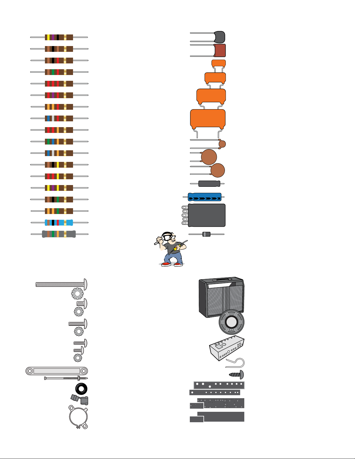
Capacitors and diode
r(1) 250pF 500V silver mica
r(1) 500pF 500V silver mica
r(3) .0033μF 600V Orange Drop
r(3) .022μF 600V Orange Drop
r(2) .047μF 600V Orange Drop
r(4) .1μF 600V Orange Drop
r(1) 10pF 500V ceramic disk
r(2) .01μF 500V ceramic disk
r(1) .02μF 500V ceramic disk
r(6) 25μF 50V Sprague Atom
r(1) 100μF 100V aluminum electrolytic
r(1) 40μF/20μF/20μF/20μF 500V filter cap
r(1) 1N4007 1000V rectifier diode
510K
332J 600V
223J 600V
473J 600V
104J 600V
+
25µF
100μf
500V
Resistors
r(1) 47Ω .5W carbon composite
r(2) 100Ω .5W carbon composite
r(1) 1K .5W carbon composite
r(4) 1.5K .5W carbon composite
r(1) 2.2K .5W carbon composite
r(1) 2.7K .5W carbon composite
r(1) 3.3K .5W carbon composite
r(1) 6.8K .5W carbon composite
r(1) 22K .5W carbon composite
r(2) 56K .5W carbon composite
r(2) 68K .5W carbon composite
r(7) 100K .5W carbon composite
r(4) 220K .5W carbon composite
r(1) 470K .5W carbon composite
r(6) 1M .5W carbon composite
r(1) 3.3M .5W carbon composite
r(1) 1K 2W metal oxide
r(2) 15K 2W metal oxide
Yellow Violet Black Gold
Brown Black Brown Gold
Brown Black Red Gold
Brown Green Red Gold
Red Red Red Gold
Red Violet Red Gold
Orange Orange Red Gold
Blue Gray Red Gold
Red Red Orange Gold
Green Blue Orange Gold
Blue Gray Orange Gold
Brown Black Yellow Gold
Red Red Yellow Gold
Yellow Violet Yellow Gold
Brown Black Green Gold
Orange Orange Green Gold
Brown Black Red Gold
Brown Green Orange Gold
Hardware
r (8) 10-32 machine screw, 3/4"
r (8) 10-32 locknut
r (6) 8-32 machine screw, 3/8"
r (10) 8-32 locknut
r (6) 6-32 machine screw, 1/2"
r (6) 6-32 locknut
r (6) 4-40 machine screw, 3/8"
r (8) 4-40 machine screw, 1/4"
r (14) 4-40 locknut
r (2) Chassis mounting strap
r (4) Chassis strap screw and nut
r (6) Rubber grommet
r (1) Strain relief for power cord
r (1) Filter cap mounting clamp
r (1) Cabinet
r (1) 10” speaker
r (1) Chassis
r (1) Cable clamp
r (1) Screw for cable clamp
r (1) Faceplate/backplate set
r (2) Eyelet boards set
r (2) Insulator boards set
Parts list
stewmac.com 4 © 2018 StewMac
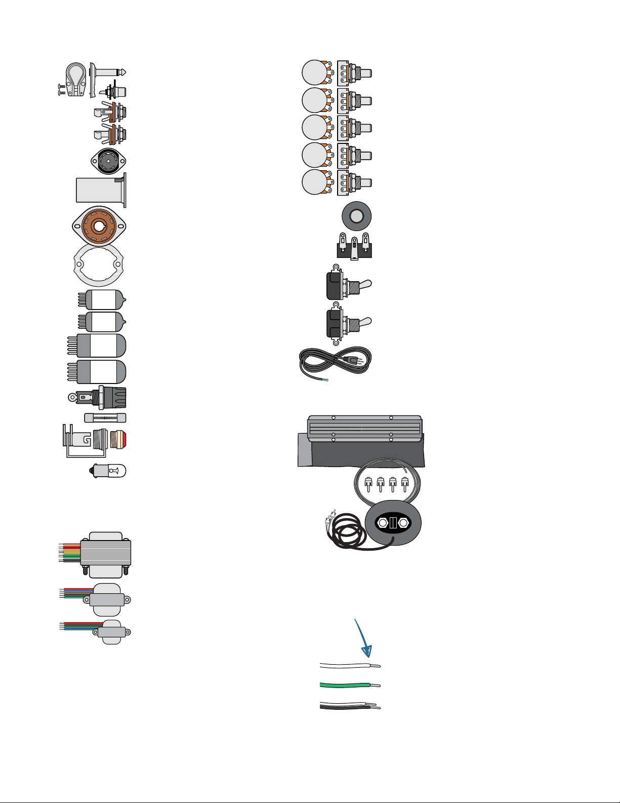
r (1) Speaker plug
r(4) RCA-style jack
r (3) Three-lug shorting jack
r (1) Two-lug mono jack
r (4) 9-pin tube socket
r (4) Shield for 9-pin socket
r (3) 8-pin tube socket
r (3) Tension clip for 8-pin socket
r (3) 12AX7 preamp tube (also called ECC83S)
r (1) 12AT7 preamp tube (also called ECC81)
r (2) 6V6S power tube
r (1) 5AR4 rectifier tube
r (1) Fuse socket
r (1) Fuse (1 amp, slow blow)
r (1) Pilot lamp socket with lens
r (1) Pilot lamp bulb (#47)
Transformers
r(1) Power transformer
r (1) Output transformer
r (1) Reverb driver
4
3
2
1
8
7
6
5
12AT712AX7 6V6 5AR4
6
4
3
2
1
9
8
7
5
r (2) 250K control pot (A–audio taper)
r (1) 1M control pot (A–audio taper)
r (1) 3M control pot (RA–reverse audio taper)
r (1) 100K control pot (L–linear taper)
r (1) 250K control pot (L–linear taper)
r (6) Knob
r (2) Three-lug ground terminal
r (2) Power switch (2 lugs)
r (1) Ground switch (3 lugs)
r (1) Power cord
Reverb
r (1) Reverb tank
r (1) Reverb tank bag
r (1) Reverb wiring kit
r (1) Reverb footswitch
Wire
r (1) White wire
r (1) Green wire
r (1) Speaker wire (two leads)
1
2
3
4
10
5
6
7
8
9
2
5
0
K
A
1
M
A
3
M
R
A
1
0
0
K
L
2
5
0
K
L
Parts list
Vintage-style push-back wire lets you push
the insulation back instead of cutting it away.
BUT: Trimming the insulation still works better.
stewmac.com 5 © 2018 StewMac
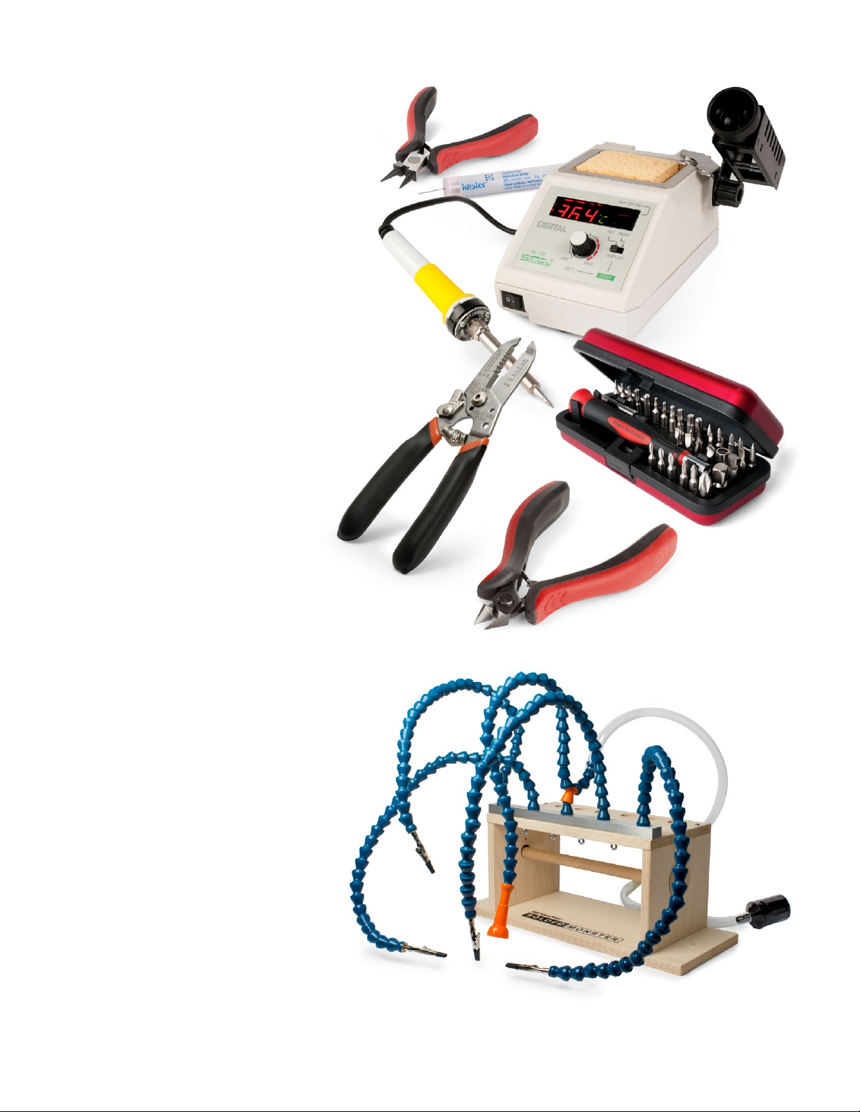
#0531
StewMac
Solder Monster
#3000
Guitar Tech
Screwdriver Set
#1606
Wire Stripper
#1607
Wire Cutter
#0501
Solomon SL-30
Soldering Station
#1609
Round Nose
Bending Pliers #0505
Kester
Pocket-Pak
Solder
StewMac’s Solder Monster
holds parts while you solder
Tools and supplies
Required Phillips screwdrivers, #1 and #2
Item #3000 Guitar Tech Screwdriver Set
Needle nose pliers
Item #1610 Long Nose Pliers
Wire cutter
Item #1607 Wire Cutter
Wire stripper
Item #1606 Wire Stripper
Soldering iron (preferably 40W)
Item #0501 Solomon SL-30 Soldering Station
Solder (at least one Pocket-Pak)
Item #0505 Kester Pocket-Pak Solder
Solder sucker
Item #0503 Solomon Solder Sucker
Drill with a 5/32" bit
For mounting eyelet board and filter cap
Ruler
Item #4905 StewMac Shop Rule
Digital multimeter
Item #3618 Fieldpiece Pocket Multimeter
Snuffer stick (bleed resistor)
Item #1552 Snuffer Stick
Copper shielding tape
Item #0028 2" Conductive Copper Tape
Pencil
Colored art markers
Wooden chopsticks
Glue
Wood glue, white glue or contact cement
for gluing a paper label inside the cabinet
Helpful Round nose bending pliers
Item #1609 Round Nose Bending Pliers
Solder wick
Item #0504 Solder Wick, 5-foot roll
Soldering aids
Item #0521 StewMac Soldering Aids
Soldering stand
Item #0506 Solomon Soldering Stand
Solder Monster, or helping hand tool
Item #0531 StewMac Solder Monster
Chassis stand
Item #10750 Chassis Stand
Printed circuit board vise
Scratch awl or center punch
Item #3000 Guitar Tech Screwdriver Set
Tray for loose parts
stewmac.com 6 © 2018 StewMac
High voltage, even when unplugged
When you turn on an amp, the capacitors are designed to
take on a charge and hold it. That stored voltage is enough
to injure you seriously, or even kill you.
These components aren’t a threat until the first time you plug
the amp in. The stored electricity can be safely discharged to
ground with a snuffer stick. See how to use it below.
Once your amp has been turned on, don’t touch the wiring
with your bare hands—even after turning it off. If you need
to press on a contact, use a chopstick or Sharpie marker,
which are both non-conductive. Don’t use a pencil, because
graphite is conductive.
It’s important that you understand the dangers so you’re
working safely. Here’s how to do it right.
Wear rubber-soled shoes
Rubber soles increase the insulation
between yourself and the ground.
Take off your ring
A metal ring on your finger can
bridge a hot connection to ground.
Wear safety glasses
Rosin-core solder sometimes bubbles up, and it can spew
molten specks into the air. You don’t want molten solder in
your eyes.
It’s better not to work alone
Electrical shocks can incapacitate you, and having someone
available to call 911 can be a lifesaver.
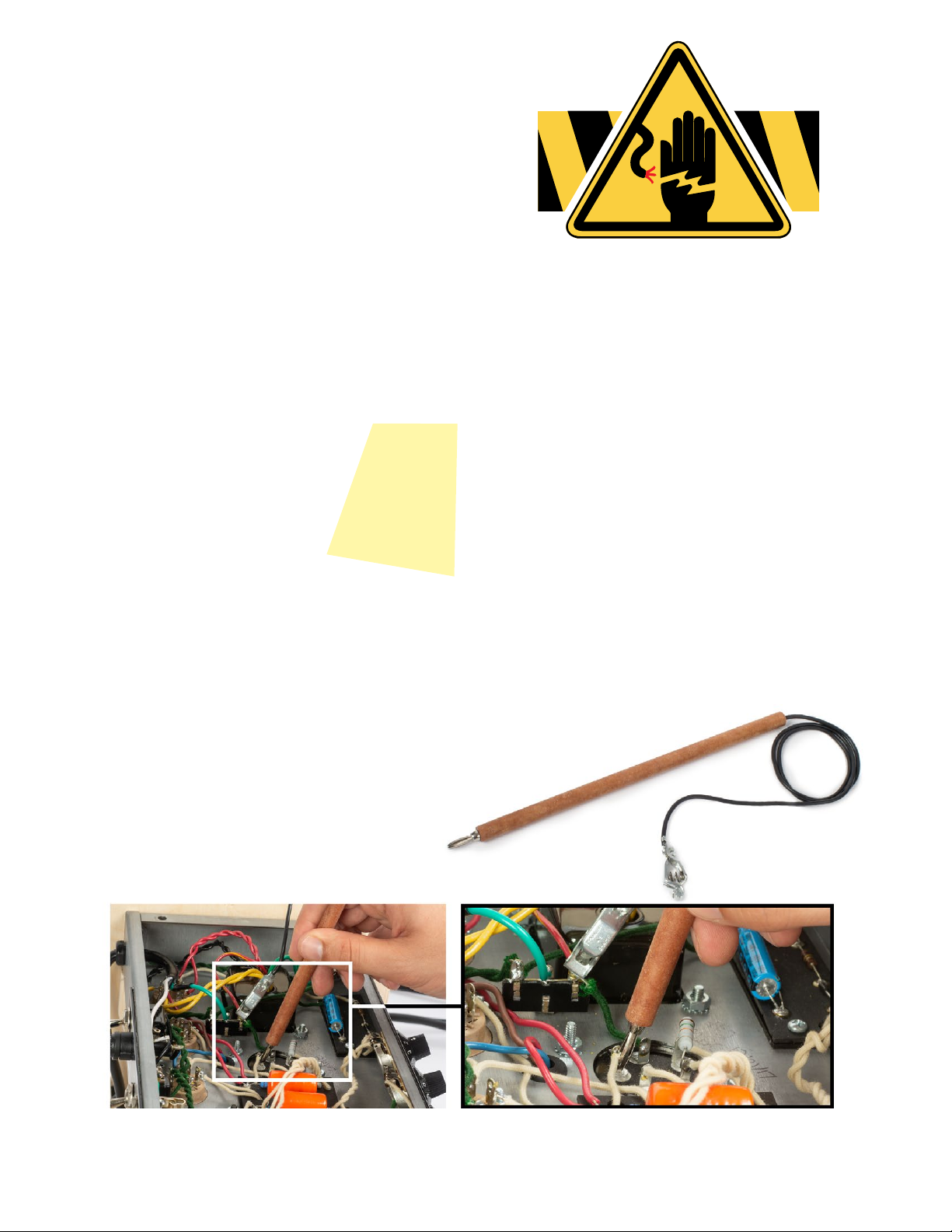
How to use a snuffer stick
To discharge a capacitor, clip the snuffer stick lead
to ground—preferably a mounting bolt on the
power transformer. Hold the tip of the stick to the
cap’s positive lead and use your multimeter to
watch the voltage drain to less than 18V.
Take breaks and stop when you’re tired
Fatigue leads to mistakes, and no one can afford mistakes
when working with electricity.
Stay suspicious
Whether it’s the first time you’ve been inside a live ampli-
fier or the 100th time, don’t become complacent. If you
discharge the caps and walk away for a few minutes, check
again for residual voltage when you return. Capacitors can
self-charge through a phenomenon known as dielectric
memory.
Check before powering on
It’s easy to forget that you a left a stray tool or wire in the
chassis. It’s also easy to forget to re-attach the speaker wire,
and that can fry an output transformer in seconds. Constant
vigilance is your friend when working on amps.
Always unplug it
Unplug the amp whenever you don’t specifically need it
plugged in. Some points are always hot when the amp’s
plugged in, even if the power switch is off. These points
include the lugs on the fuse socket, power switch, and
standby switch.
Amp voltages are seriously dangerous!
Professionals
who work on
amps take these
safety habits
very seriously

stewmac.com 7 © 2018 StewMac
A resistor’s value—the amount of resistance it creates—is
rated in ohms (Ω ). Larger ohm values mean more resistance.
For example, a 100Ω resistor creates ten times as much re-
sistance as a 10Ω resistor.
The resistors used in amplifiers are too small to have value
numbers printed on them. Instead, a system of colored
bands tells their values. The key to reading these bands is
provided below. However, an easier way to decode these
bands is to download one of the many smartphone apps
for this purpose.
One band will be the nearest to an end of the resistor. That
band tells the first value. Combine it with the value of band
2 to get a two-digit number (68 in our example below).
Multiply that number by band 3 (68 x 1,000 = 68,000). Thou-
sands are represented by the letter K, so this resistor is 68K
(kilo-ohms, or KΩ).
If there is a fourth band, it will be either silver or gold. This
indicates the tolerance allowed during manufacturing. The
resistors used in this kit have a +/- 5% tolerance, represented
by a gold band 4.
A magnifying glass helps a lot. The bands on a 470Ω resistor
are yellow/violet/brown, and the bands on a 47K resistor are
yellow/violet/orange. They’re easily confused!
Can’t read the colors?
You can always use a multimeter to test a resistor’s value.
Set your meter to ohms and connect the test leads on each
side of the resistor.
Capacitor values are typically printed on the component.
The key values with caps are their capacitance and voltage.
Think of a capacitor as a container that can hold electricity.
Capacitance, measured in farads, refers to how much elec-
tricity this container can hold—its capacity. One farad (1F)
would be much too large for use in an amplifier. Caps for
amps are rated in millionths of a farad, called microfarads
(μF), or trillionths of a farad: picofarads (pF). The voltage
spec for a cap refers to how much DC voltage it can handle
at any given time.
A unique property of capacitors is that they don’t allow DC
current to flow past them, only AC current. This is important
in parts of an amplifier circuit, such as the path between a
preamp stage and a power amp stage. Here, a “coupling
capacitor” will block DC voltage, allowing only the AC guitar
signal to pass.
Filter caps
Capacitors also filter out 60Hz hum, or “ripple,” after the AC
current from the wall is converted to DC. These capacitors
are called filter caps, because they filter out the ripple from
a power supply. The filter caps in this amp are the 8μF and
16μF electrolytic capacitors.
Electrolytic caps
Electrolytic capacitors contain electrolyte: a liquid or gel
that gives them a large storage capacity. Electrolytic caps
are typically polarized.
Polarized caps
Some capacitors have polarity and some don’t. It’s extremely
important to install polarized caps correctly in a circuit. The
positive lead of an electrolytic cap will be indicated by an
indented ring around one edge of the capacitor. The nega-
tive lead will often be indicated by a band of arrows pointing
to the negative lead.
Installing capacitors with the polarity backwards will make
the circuit malfunction and quickly destroy the capacitor—
even causing it to explode.
Band 1 Band 2 Band 3 Band 4
1st Digit 2nd Digit Multiplier Tolerance
6 8 x1,000 +/- 5%
68K +/- 5%
K=1,000
Blue
Read this band first (closest to an end)
Gray Orange Gold
BLACK 0 0 1 None +/- 20%
BROWN 1 1 10
RED 2 2 100
ORANGE 3 3 1,000
YELLOW 4 4 10,000
GREEN 5 5 100,000
BLUE 6 6 1,000,000
VIOLET 7 7
GRAY 8 8 0.01 +/- 10% SILVER
WHITE 9 9 0.1 +/- 5% GOLD
NegativePositive
+
25μF
8μf
How to read resistor values Capacitor values
stewmac.com 8 © 2018 StewMac
STEP 3
Solder the speaker leads
Twist the speaker leads together to
keep them neat.
Push the insulation back 3/8" and in-
sert the white lead into the speaker’s
positive terminal and the black lead
into the negative terminal.
Before soldering these leads, place
a business card or other protection
under the terminals to prevent sol-
der dripping onto the speaker cone.
Solder the two leads to the speaker
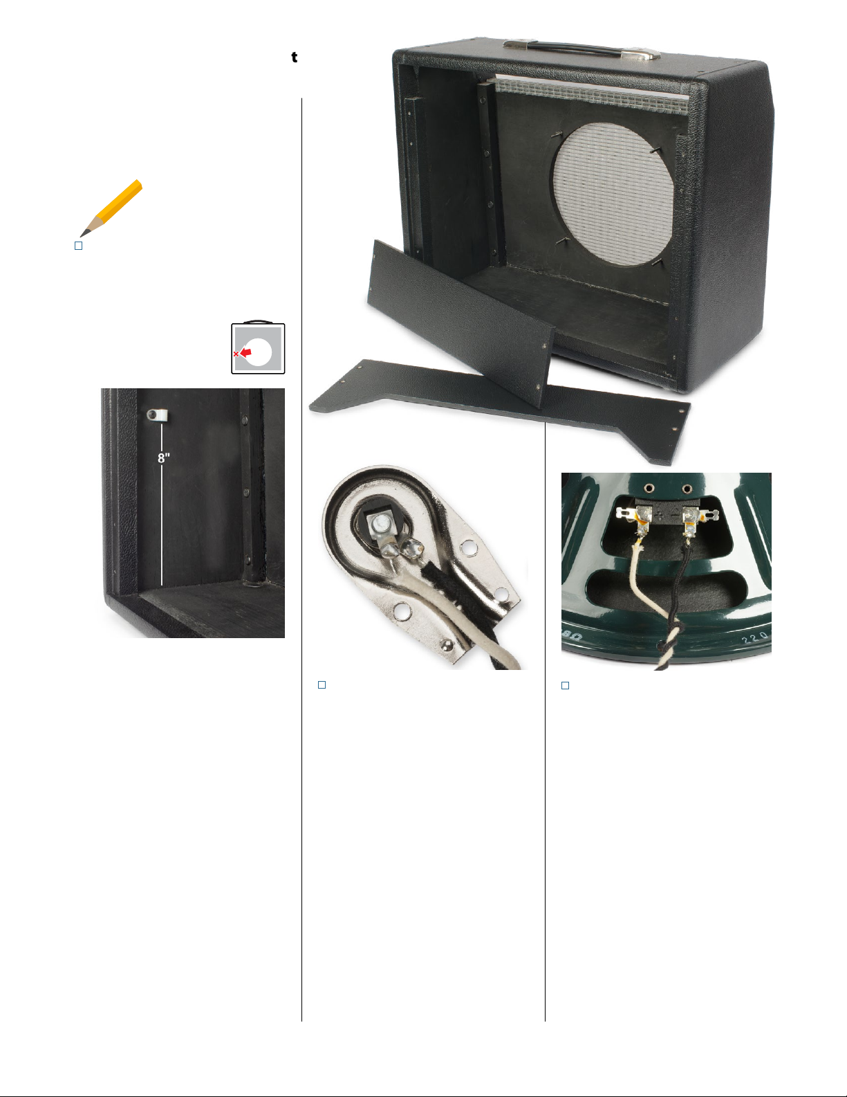
terminals.
Prepare the cabinet for mounting the
amp chassis by first removing the two
back panels.
STEP 1
Mount the power cord clamp
Drill a 5/64" pilot hole to mount the
nylon cable clamp. Locate the clamp
inside the left wall of the
cabinet, 8" up from the
bottom and 1" in from the
panel mounting ledge.
Don’t drill through the cabinet! Use a
piece of masking tape on your drill bit
to mark the depth, or use a StewMac
Depth-stop Drill Bit (item #1712).
Use the black cable clamp screw to
mount the clamp. You’ll secure the
power cord with this clamp later, after
the testing.
Start by prepping the cabinet
Check off each
completed step
STEP 2
Solder the speaker plug
Use a small screwdriver to remove the
back of the speaker plug.
On the black and white speaker leads,
push the insulation back 3/8". Solder
the white positive lead to the tip lug
(center of the plug).
Trim the black lead and solder it to the
sleeve lug. The solder joints need to
be neat so they won’t short against
the metal case. See “Tips for great
soldering” on page 11.
Reassemble the plug and do a con-
tinuity test with your multimeter
to make sure there’s no connection
between the plug’s tip and its metal
case (see page 43).
Back
Here

stewmac.com 9 © 2018 StewMac
’65 P-REVERB 15W
ORIGINAL A A1 1 6 4 CIRCUIT
StewMac®
ICON KITS
Use only 1-amp slow-blow fuse.
DANGER: Unplug the amp before changing tubes.
Tube locations from left to right:
5AR4
(GZ34) 6V6 6V6 12AT 7
(ECC81)
12AX7
(ECC83)
V7 V6 V5 V2 V1
12AX7
(ECC83)
12AX7
(ECC83)
V4 V3
STEP 7
Solder four RCA plugs
The shielded wire is in two 3-foot
lengths. At the ends of each piece, pull
3/4" of the wire mesh shielding away
to one side and strip away 3/8" of the
internal cloth shielding. Insert the
exposed wire into an RCA plug so that
it reaches the tip of the center post.
Solder this lead in place at the tip of
the plug. Don’t leave solder on the
outside of the plug tip which would
keep it from fitting into the jack. See
“Tips for great soldering” on page 11.
After the plug tip cools and the inside
solder joint is set, solder the braided
wire shielding onto the outside of the
plug. Solder the four RCA plugs this
way, on each end of the two cables.
These two cables will connect the
reverb tank.
Test for continuity between the tips
of the plugs on each cable, then test
for continuity between the shields of
the plugs in the same way.
Also test to make sure you don’t
have continuity between the tip and
the shield of each plug, which would
indicate a short in the jumper. If your
multimeter finds unwanted continu-
ity, the likely culprit is the inside (tip)
wire shorting to the outer shield. If
that happens, de-solder the tip con-
nection and redo that solder joint.
STEP 5
Install the faceplate + backplate
Secure the faceplate by putting the
Volume and Bass control pots in their
holes and sliding the faceplate over
them. Install washers and nuts on the
pots to hold the plate in place.
Use the 1MA pot for Volume and a
250KA pot for Bass. Install them with
their lugs facing up for soldering. See
the wiring diagram on Page 12.
Install the backplate the same way,
using the 2-lug extension speaker jack
and the 3-lug ground switch.
This switch is just for looks, because
ground switches are not needed in
modern amps with 3-wire grounding
power cords. But having it there keeps
the vintage 1960s look.
Mount the ground switch so it toggles
left/right rather than up/down.
STEP 6
Glue the tube placement chart
Cut out the tube replacement chart
on page 51. Put a thin coat of glue
or contact cement on the back
and glue it to the inside wall of the
cabinet.
STEP 4
Install the speaker
Remove the nuts from the four
speaker mounting screws. Carefully
slide the speaker onto the mounting
screws until it’s flush with the front
panel.
Install the mounting nuts so they
lightly touch the speaker frame.
Do not tighten the nuts in a circular
pattern around the speaker, because
this can warp the speaker frame.
Instead tighten one nut with a quarter
turn so it’s just snug, then do the same
to the opposite side. Then snug the
third nut and fourth. Repeat this criss-
cross pattern of quarter-turns until all
four nuts have had one full turn. This
will give proper tension to compress
the speaker gasket. Overtightening
can damage the cone and cause un-
wanted distortion.
Criss-cross
tightening
prevents warping.

stewmac.com 10 © 2018 StewMac
This circuit is built on two eyelet
boards: the large main board and a
smaller one called the bias board. For
each of these, there’s an additional
blank insulator board of the same size.
These insulators mount behind the
eyelet boards to prevent the com-
ponents from contacting the metal
chassis.
Each pair of boards will mount to the
chassis with two machine screws.
The first step in preparing these
boards is to drill mounting holes
through the blank insulators.
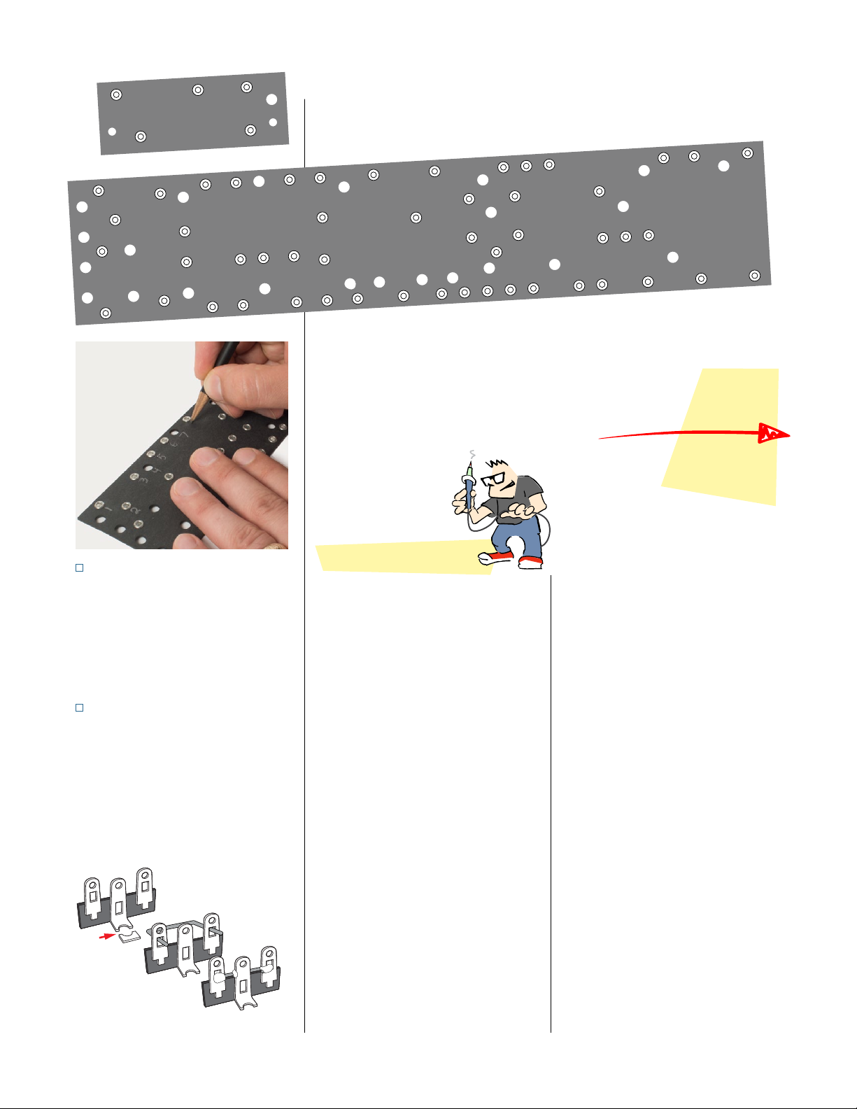
Prepping the eyelet boards
STEP 8
Drill the insulator boards
Noting the eyelet holes, orient the
boards as shown above. Align each
eyelet board with its insulator and
tape them together.
The mounting holes are pre-drilled
in the main eyelet board, but not in
its insulator board. Drill through the
holes indicated using a 5/32" drill
bit. Separate the boards and set the
insulator board aside for later.
The smaller bias board does not have
pre-drilled mounting holes. Place it
in the chassis as shown. Holding the
board in position, turn the chassis
over to see the mounting holes.
With a sharp pencil, mark the two
hole locations onto the insulator
board. Drill two 5/32" mounting holes
through this pair of boards. Set the
insulator board aside for later.
You'll drill the mounting holes in the bias board.
In the main board, they're already drilled.
Insulator
stewmac.com 11 © 2018 StewMac
STEP 9
Number the eyelets and holes
These instructions will refer to the
eyelets and holes on the main eyelet
board by number and the bias board
by letter. Use a pencil to mark these
numbers and letters onto the boards.
STEP 10
Prep one grounding strip
With a wire cutter, snip the mounting
holes on a 3-lug terminal strips as
pictured. Cut a 1" piece of green wire
and remove the insulation. Wrap and
solder the wire across the terminals,
electrically connecting all three lugs.
This will be used as a grounding strip.
Snip
Wrap
Solder
15
34
2
10
59
20
17
678911
58
57
56
55
54 60 61 62 63 64 65 68 69 70
71
72
73
74
66 67
12
13
14 15 16 18 19 21
24 25 26
27 30
29
28 31
22 23
32 33 34 35
37 40 41 42
43 44 45 46 47 48 49 50 51 52 53
38
39
36
ABC
D
EF
Tips for great soldering!
nWrap the leads tightly for a good
electrical contact before soldering.
Don’t use solder to “glue” loose joints.
nMelt a small amount of solder onto
the tip of the iron (“tinning” the iron).
Hold the tip against the connection
until the connection reaches solder-
ing temperature. This should take just
a few seconds.
Also tin component leads like multi-
strand wires to help the solder flow
for a better joint.
nKeep your soldering tip clean by
wiping it often on a damp sponge.
And keep it tinned by occasionally
melting a little solder onto it.
nFeed solder to the connection, not
to the iron. Stop feeding solder once
an eyelet is filled. Keep the iron on
the connection for a second longer
to allow time for all of the flux to cook
out of the joint.
nDon’t ever blow on the hot solder,
or touch anything until the joint is
completely cool. A good solder joint
is shiny—a sign that it was left to cool
undisturbed.
nAfter the joint has cooled, trim away
the excess wires.
nPlan ahead so each joint is only
soldered once. Resoldered joints are
messy and more likely to fail.
nPosition the parts so their specs face
out so you can read them later. Many
builders also align resistor bands to
read in the same direction.
nHow much insulation to strip? With
plastic insulation, strip 3/8" from the
wire ends. Push-back wire works best
when you strip away about 1/4" of the
cloth wrap.
You’re ready to build!
stewmac.com 12 © 2018 StewMac
VIBRATO
PEDAL
REVERB
PEDAL
REVERB
OUTPUT
REVERB
INPUTSPEAKERPOWERGROUND FUSE EXTENSION
PILOT
LAMP
V7
5AR4
V6
6V6
V5
6V6
V4
12AX7
V3
12AX7
V2
12AT7
V1
12AX7
INTENSITY SPEED REVERB BASS TREBLE VOLUME INSTRUMENTS
2 1
POWER
TRANSFORMER FILTER CAP
OUTPUT TRANSFORMER
(mounted outside)
REVERB DRIVER
(mounted outside)
4
3
2
1
8
7
6
5
4
3
2
1
8
7
6
5
4
3
2
1
8
7
6
5
6
4
3
2
1
9
8
7
5
6
4
3
2
1
9
8
7
5
6
4
3
2
1
9
8
7
5
6
4
3
2
1
9
8
7
5
O
–
U
X
Y
2
5
0
K
A
1
M
A

stewmac.com 13 © 2018 StewMac
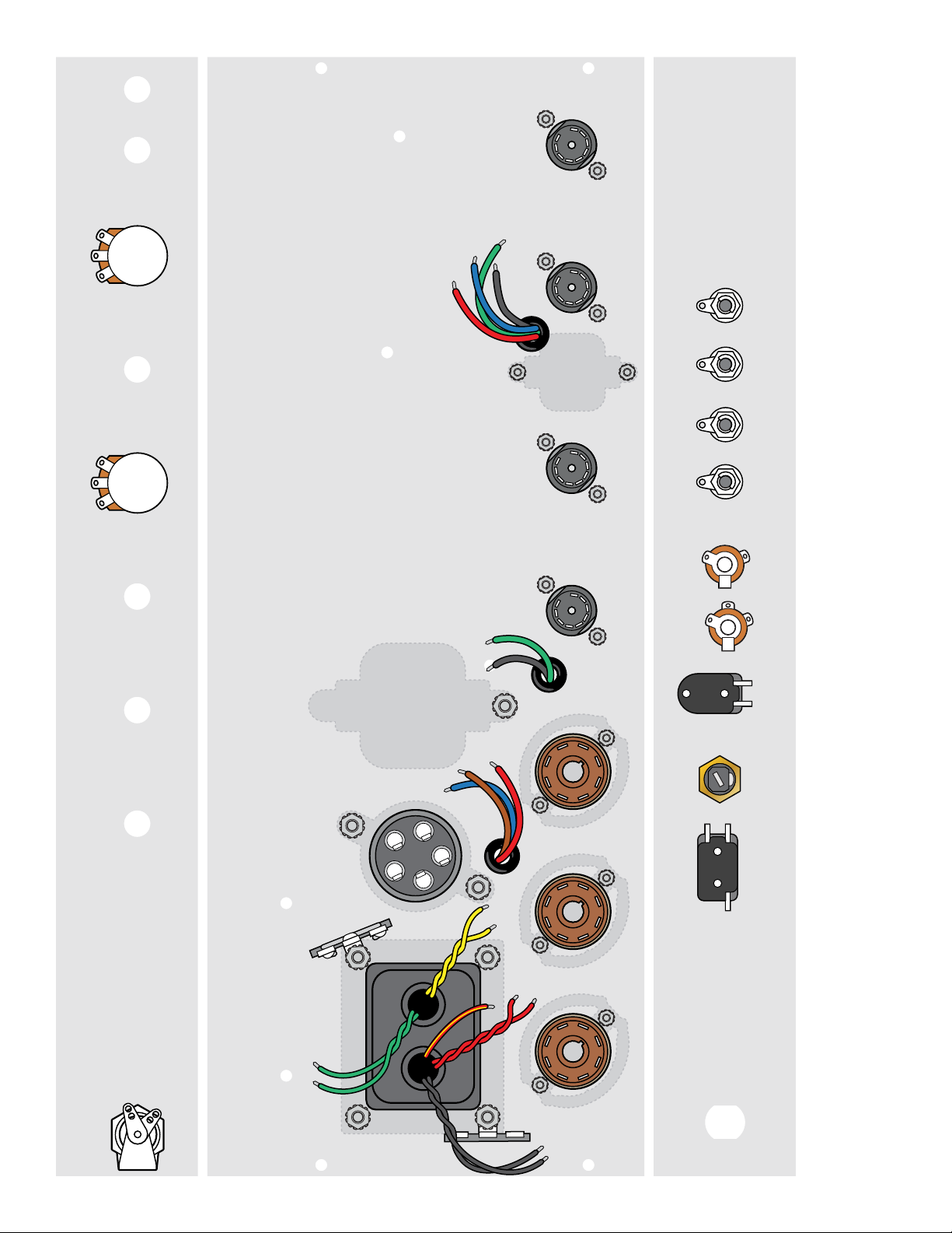
Installing the chassis-mounted components
STEP 11
Mount the power transformer
and two 3-lug terminal strips
The power transformer has nine leads
color-coded in four pairs, plus a single red/
yellow striped lead. Twist the same-color
pairs together. Feed all the leads into the
chassis through the square hole.
Install the transformer on the outside
of the chassis, using four 8-32 locknuts
inside. Mount the two terminal strips
under the locknuts at the front and back
corners as shown: the one you’ve turned
into a grounding strip goes to the front.
STEP 12
Install three rubber grommets
Squeeze these into the three holes as
shown. These grommets provide strain
relief for the transformer wires that will
pass through the metal chassis.
STEP 13
Mount the output transformer
The output transformer has red, blue,
brown, black, and green leads. Thread the
red, blue and brown leads through the
left rubber grommet as pictured in the
diagram, and the black and green leads
through the middle grommet.
Using two 8-32 x 1/4" machine screws,
mount the transformer to the outside of
the chassis.
STEP 14
Mount the reverb driver
The reverb driver is a transformer with
red, blue, green, and black leads. Thread
these four leads through the remaining
rubber grommet.
Use two 8-32 x 1/4" machine screws to
mount the reverb driver on the outside
of the chassis.
STEP 15
Mount the filter capacitor
The large filter cap mounts to the chassis
with the filter capacitor mounting clamp.
The clamp attaches to the end of capaci-
tor near the lugs, and then mounts to the
chassis using 6-32 x 1/2" machine screws
and locknut. If needed, enlarge the screw
holes by drilling them with a 5/32" bit.
Attach the clamp so that the capacitor’s
negative lug (marked “–”) is closest to the
power transformer, as shown.
STEP 16
Install the speaker output jack
Add the 3-lug speaker output jack next
to the 2-lug extension speaker jack which
you’ve already installed.
These jacks are electrically grounded
through contact with the metal chassis,
so tighten them well for a good ground.
STEP 17
Install the three large tube sockets
with tension clips
Orient these 8-pin tube sockets so that
pin 1 is closest to the rear panel of the
chassis.
Use 4-40 x 3/8" machine screws to mount
these sockets on the outside of the chas-
sis. Include a tension clip on top of each
socket to provide support for these three
tubes when they’re installed later.
STEP 18
Install the four small tube sockets
Use two 4-40 x 1/4" machine screws to
mount the four remaining tube sockets.
Position these sockets so pin 3 is closest
to the rear panel of the chassis.
STEP 19
Install the fuse socket
Mount the fuse socket so its side lug
faces the open side of the chassis. This
orientation makes it easier to solder later.
STEP 20
Install the power switch
Mount the power switch with its two lugs
facing up for soldering later.
STEP 21
Install the four RCA jacks
Mount the RCA jacks to the chassis with
the large washers on the outside. Once in-
stalled, bend the grounding tabs slightly
away from the inside of the chassis.
STEP 22
Install the pilot lamp socket
Mount the socket by screwing the lens
from the outside into the socket as-
sembly. Position the socket so the arm
supporting the lamp faces the side wall
of the chassis.
Some amp builders add a drop of glue to
the mounting threads to keep vibrations
from loosening the socket from high-vol-
ume playing.
stewmac.com 14 © 2018 StewMac
VIBRATO
PEDAL
REVERB
PEDAL
REVERB
OUTPUT
REVERB
INPUTSPEAKERPOWERGROUND FUSE EXTENSION
PILOT
LAMP
V7
5AR4
V6
6V6
V5
6V6
V4
12AX7
V3
12AX7
V2
12AT7
V1
12AX7
INTENSITY SPEED REVERB BASS TREBLE VOLUME INSTRUMENTS
2 1
4
3
2
1
8
7
6
5
4
3
2
1
8
7
6
5
4
3
2
1
8
7
6
5
6
4
3
2
1
9
8
7
5
6
4
3
2
1
9
8
7
5
6
4
3
2
1
9
8
7
5
6
4
3
2
1
9
8
7
5
OU
X
Y
O
–
U
X
Y
2
5
0
K
A
2
5
0
K
A
1
M
A
3
M
R
A
1
0
0
K
L
2
5
0
K
L

stewmac.com 15 © 2018 StewMac
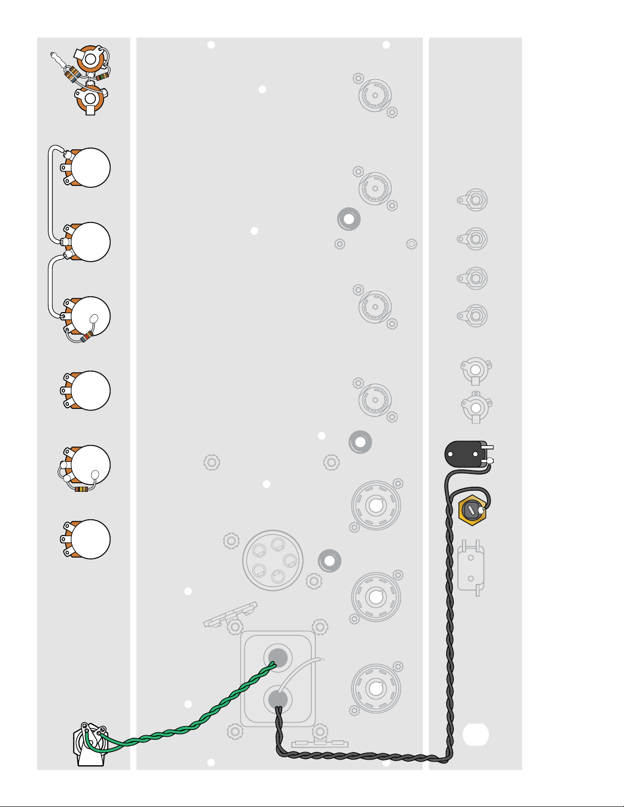
STEP 23
Install the remaining control pots
Mount the control pots with their lugs
facing up for soldering. When we refer to
lugs as left or right, it’s assuming you’re
looking at the pot from the same point
of view as in the wiring diagram.
Mount them as follows:
Intensity: 250KL pot
Speed: 3MRA pot
Reverb: 100KL pot
Bass: 250KA pot
Treble: 250KA pot
Volume: 1MA pot
STEP 24
Install 100K resistor + 6.8K resistor
Run one lead of the 100K resistor up
through the bottom of the left lug of the
speed pot and wrap it down through the
middle lug of the same pot. It doesn’t
matter which direction this resistor is in-
stalled, because resistors aren’t polarized.
Solder the resistor lead to both lugs.
Solder the other lead of this resistor to
the back of the speed pot.
Wrap one lead of the 6.8K resistor through
the left lug of the bass pot but don’t sol-
der this connection yet.
Solder the 6.8K resistor’s other lead to the
back of the bass pot.
STEP 25
Install two jumpers
Cut two white wires, 2" long. Connecting
wires like this are called jumpers.
Wrap one end of a jumper onto the mid-
dle lug of the bass pot and wrap the other
end of this jumper onto the left lug of the
treble pot. Solder the connection to the
left lug of the treble pot, but leave the
middle lug of the bass pot unsoldered
for now.
Wrap one end of the other jumper onto
the middle lug of the treble pot. Wrap
the other end onto the right lug of the
volume pot. Solder the connections at
both ends of this jumper.
STEP 26
Install two jacks + a 1K resistor
Add instrument jacks 1 and 2. Position
them so the center lug of jack 2 is close to
the side lug of jack 1 as pictured.
Wrap one lead of a 1M resistor through
the right lug of jack 1 and wrap it onto
the center lug of the same jack. Make
sure this lead won’t be in the way when
an instrument cable is plugged in.
Run this resistor’s other lead through the
left lug of jack 1 and onto the center lug of
jack 2. Don’t solder these connections yet.
STEP 27
Install two 68K resistors
Twist the leads of the two 68K resistors
together, creating one connection. Wrap
the other lead from one resistor onto the
right lug of jack 2 as shown.
Wrap the remaining resitor lead onto the
left lug of jack 1, adding it to the connec-
tion made in the previous step.
Solder all these connections, and also
solder the twisted 68K resistor leads.
STEP 28
Power transformer black leads
Run either of the black wires from the
power transformer to the side lug of the
fuse socket. Trim it to fit and solder it. Trim
and solder the other black wire to the left
lug on the power switch.
STEP 29
Power transformer green leads
Run the two green wires from the power
transformer to the lugs on the pilot lamp
socket (either wire can go to either lug).
Trim these wires to length and wrap
them onto the lugs. Don’t solder these
connections yet.
Despite being green, these aren’t
ground wires. They power the pilot
lamp and tube heater filaments.

stewmac.com 16 © 2018 StewMac
VIBRATO
PEDAL
REVERB
PEDAL
REVERB
OUTPUT
REVERB
INPUTSPEAKERPOWERGROUND FUSE EXTENSION
PILOT
LAMP
V7
5AR4
V6
6V6
V5
6V6
V4
12AX7
V3
12AX7
V2
12AT7
V1
12AX7
INTENSITY SPEED REVERB BASS TREBLE VOLUME INSTRUMENTS
2 1
4
3
2
1
8
7
6
5
4
3
2
1
8
7
6
5
4
3
2
1
8
7
6
5
6
4
3
2
1
9
8
7
5
6
4
3
2
1
9
8
7
5
6
4
3
2
1
9
8
7
5
6
4
3
2
1
9
8
7
5
OU
X
Y
O
–
U
X
Y
4
3
2
1
8
7
6
5
4
3
2
1
8
7
6
5
4
3
2
1
8
7
6
5
6
4
3
2
1
9
8
7
5
6
4
3
2
1
9
8
7
5
Enlarged to
show detail

stewmac.com 17 © 2018 StewMac
STEP 30
Power transformer red/yellow lead
Trim the power transformer’s red/yellow
lead to an appropriate length and solder
it to the front grounding strip as shown.
STEP 31
Power transformer red leads
Trim the power transformer’s red leads to
an appropriate length and wrap one lead
onto pin 4 of the V7 tube socket (5AR4).
Socket pins have upper and lower eyelets
for multiple connections.
Wrap the other red lead onto pin 6 of
the same socket. Don’t solder these red
leads yet.
STEP 32
Power transformer yellow leads
Trim the power transformer’s yellow leads
to an appropriate length. Wrap one of
these leads onto pin 2 of socket V7.
Wrap the other yellow lead onto pin 8
of the same socket. Don’t solder these
yellow leads yet.
STEP 33
Output transformer
blue and brown leads
Trim the blue wire from the output trans-
former to an appropriate length and wrap
it onto pin 3 of socket V5. Don’t solder this
connection yet.
Trim the brown wire from the output
transformer to an appropriate length
and wrap it onto pin 3 of socket V6. Don’t
solder this connection yet.
Leave the red output transformer lead
free for now, you’ll connect it later, when
the eyelet board is installed.
STEP 34
Two jumpers
Add a 1-1/2" white jumper between the
right lug of the speaker jack and the right
lug of the extension jack. Wrap these
joints, but do not solder them yet.
Cut a 3/4" white jumper and remove the
insulation. Add this short wire between
the speaker jack’s left lug and center lug.
Solder the both ends.
STEP 35
Output transformer green and
black leads
Trim these two wires to reach the speaker
jack and extension speaker jack.
Solder the green lead to the right lug of
the speaker jack along with the jumper
from the previous step.
Solder the black lead to the left lug of the
extension speaker jack.
STEP 36
Connect the reverb driver leads
Trim the green lead to reach the middle
lug of the reverb input jack, tin it and
solder it to the lug.
Trim the black lead to reach the ground
tab on the reverb input jack. Tin it and
solder it to this tab.
Trim the blue lead to reach pin 6 of socket
V2. Tin it and wrap it onto the pin, but
don’t solder it yet.
Leave the red lead free for now, you’ll
connect it to the eyelet board later on.
STEP 37
Add three white jumpers
Cut two 3/4" white jumpers. Wrap one of
them between pin 2 and pin 7 of socket
V2. Solder the connection to pin 2.
Wrap the second short jumper between
pin 3 and pin 8 of socket V2. Solder the
connection to pin 3.
Cut a 2" white jumper and connect it be-
tween pins 1 and 6 on socket V2. Route
this jumper in a semicircle around the
socket. Solder this jumper at pin 1 and
also at pin 6 where it joins the blue wire
from the reverb driver.
For neat looking wiring, use wire
strippers to trim 1/4" of the insulation
from the ends of the push-back wire.

stewmac.com 18 © 2018 StewMac
VIBRATO
PEDAL
REVERB
PEDAL
REVERB
OUTPUT
REVERB
INPUTSPEAKERPOWERGROUND FUSE EXTENSION
PILOT
LAMP
V7
5AR4
V6
6V6
V5
6V6
V4
12AX7
V3
12AX7
V2
12AT7
V1
12AX7
INTENSITY SPEED REVERB BASS TREBLE VOLUME INSTRUMENTS
2 1
6
4
3
2
1
9
8
7
5
6
4
3
2
1
9
8
7
5
6
4
3
2
1
9
8
7
5
4
3
2
1
8
7
6
5
4
3
2
1
8
7
6
5
6
4
3
2
1
9
8
7
5
6
4
3
2
1
9
8
7
5
6
4
3
2
1
9
8
7
5
4
3
2
1
8
7
6
5
4
3
2
1
8
7
6
5
O
–
U
X
Y
6
4
3
2
1
9
8
7
5
Table of contents
Other StewMac Amplifier manuals


