StewMac 57 MINI TWEED User manual
’57 MINI TWEED 5W
COMBO AMP KIT
ORIGINAL 5F1 CIRCUIT
ASSEMBLY INSTRUCTIONS
One-knob
titan of tone.
With loads of
helpful tips!

stewmac.com 2 © 2018 StewMac
Contents
About this iconic amp ............................................ 1
...................................................
2
Parts list ........................................................... 3
Tools and supplies ................................................ 5
Amp voltages are seriously dangerous! .......................... 6
How to use a snuffer stick ........................................ 6
How to read resistor values ...................................... 7
Capacitor values .................................................. 7
Complete wiring diagram ........................................ 8
Prepping the cabinet ............................................. 9
Prepping the boards ............................................. 11
Installing the chassis-mounted components ................... 12
How to wrap and solder the eyelet board ....................... 16
Tips for great soldering ......................................... 16
Wrapping parts onto the eyelet board .......................... 17
Soldering and installing the boards ............................ 21
Installing the eyelet board and insulator board ................ 22
Connecting the eyelet board and chassis components ......... 22
Final assembly ................................................... 25
Testing and troubleshooting .................................... 26
Learning more: secrets revealed in the schematic .............. 28
5F1 circuit schematic ............................................ 29
Mounting hole template ........................................ 33
Tube replacement chart ......................................... 35
COPYRIGHT WARNING
This material is protected by copyright and has been created by and solely for the purposes of StewMac.
You may not sell, alter or further reproduce any part of this material, or distribute it to any other per-
son. Where provided to you in electronic format, you may only print from it for your own private use.
Failure to comply with the terms of this warning exposes you to legal action for copyright infringement.
How to build this kit!

stewmac.com 1 © 2018 StewMac
Iconic Tweed tone
is now in your hands
Be excited!
Your new StewMac ’57 Mini Tweed will be a blast
to play through and even more fun to build.
This one-knob titan of tone takes you from jazz
to blues, from restrained to rockin’, and from
clean to clobbered, all at volumes that won’t
get you evicted.
This amp is an ICON
The ’57 Mini Tweed is a timeless studio darling whose tiny size contradicts
its impressive punch and versatility.
Its 5F1 amp circuit was introduced in the mid-1950s as a “student” amp.
It wasn’t kid stuff for long; rock’s finest guitarists adopted it for some of
the greatest solos ever recorded. These artists include Joe Walsh and
Eric Clapton (listen to “Layla” while you build this kit!).
StewMac ICON KITS bring classics that are no longer made, or are simply
unaffordable, within reach. And the best part is you get to build them
with your own hands.
We give painstaking attention to parts selection, authentic materials, and
instantly recognizable details—everything that makes the originals so
sought after.
Build it with StewMac
These immersive instructions walk you through every step of creating
your pint-sized prince of rock-n-roll. And you’ll learn a lot, gaining a deep
knowledge of your amp’s inner workings.
Follow our steps closely for safety, too: we’ve carefully laid out a path that
even newcomers can follow in handling electrical components.
Building an amp can seem daunting, but nobody makes it easier than
StewMac. Watch for helpful tips along the way, too—we’re here to help!
Let’s get building!
’57 MINI TWEED 5W
COMBO AMP KIT ORIGINAL 5F1 CIRCUIT
stewmac.com 2 © 2018 StewMac
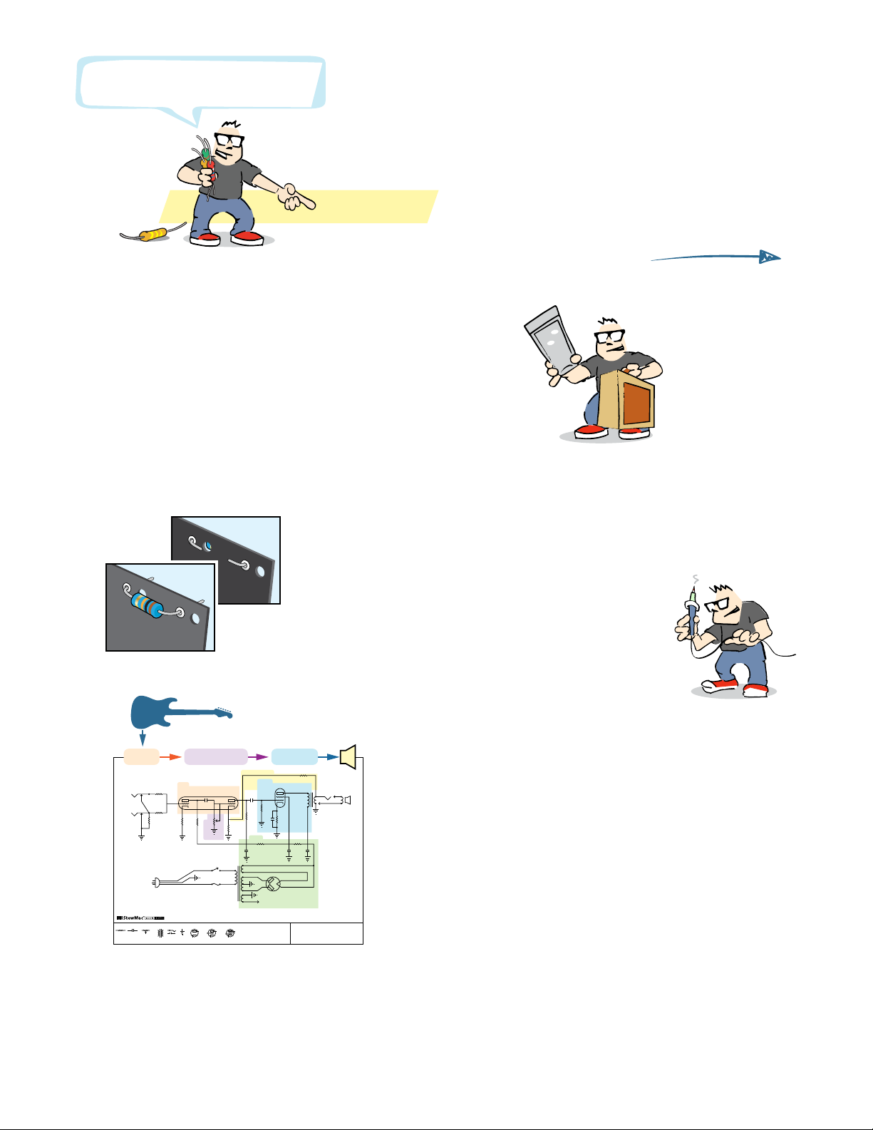
Here’s how to build this amp!
See page
1
6
Wiring goes like this:
1. First, you’ll wrap the leads, connecting them without solder.
2. Then double-check all the connections. Don’t rush!
3. When everything checks out, it's time to solder.
The numbered steps tell you when.
Get the cabinet ready,
starting at Step
1
on page
9
.
You’ll prep the metal chassis
and the eyelet board too.
Learn more:
You don’t need to read the schematic, but it’s fun!
See how your guitar’s signal gets processed into sound
on page 28.
Sort your components by type, using the parts list.
Quick look:
#10730 © 2018 StewMac
’57 T WEED 5W
5F1 CIRCUIT SCHEMATIC
Resistor Capacitor GroundJackTransformerPotentiometer Diode tube
plate
cathode
Triode tube
plate
grid
cathode
Pentode tube
grid
plate
cathode
screen
Power
Gain
Negative Feedback
Processing
Output
Power
4Ω
2
68K
22K 10K 2W
AC switch
To tube heaters and pilot light
.022 µF
25µ F 25V
470 1W
8–450
8–450
16–450
.022 µF
1 MEG
1 MEG
100 K
1.5 K
220 K
1.5 K
100 K
22 K
68K
1
12AX7
6V6 GT
5Y3 GT
1 amp
slow-blow fuse
OutputGain Processing

stewmac.com 3 © 2018 StewMac
+
25µF
473J 600V
223J 600V
8μf
16μf
r(1) Cabinet
r(1) Chassis
r(1) Eyelet board
r(1) Insulation board
r(1) 4Ω, 8" speaker
A magnifier helps!
Resistors
r(2) 100Ω .5W carbon composite
r(2) 1.5K .5W carbon composite
r(2) 22K .5W carbon composite
r(2) 68K .5W carbon composite
r(1) 220K .5W carbon composite
r(2) 100K .5W carbon composite
r(1) 1M .5W carbon composite
r(1) 470Ω 1W carbon film
r(1) 10K 2W metal oxide
Hardware
r(2) 10-32 machine screw, 1-1/2"
r(2) 10-32 locknut
r(2) 8-32 machine screw, 1/4"
r(6) 8-32 locknut
r(2) 6-32 machine screw, 1/2"
r(2) 6-32 locknut
r(4) 4-40 machine screw, 3/8"
r(2) 4-40 machine screw, 1/4"
r(6) 4-40 locknut
r(1) Black wood screw
r(1) Strain relief for power cord
r(1) Cable clamp for power cord
r(2) Rubber strain relief grommet
Capacitors
r(1) .047μF 600V Orange Drop
r(2) .022μF 600V Orange Drop
r(1) 25μF 50V Sprague Atom
r(2) 8μF 475V electrolytic filter cap
r(1) 16μF 475V electrolytic filter cap
Brown Black Brown Gold
Brown Green Red Gold
Red Red Orange Gold
Blue Gray Orange Gold
Red Red Yellow Gold
Brown Black Yellow Gold
Brown Black Green Gold
Yellow Violet Brown Gold
Brown Black Orange Gold
Parts list

stewmac.com 4 © 2018 StewMac
Tubes, lamps, fuses, and sockets
r(1) Speaker jack
r(1) Speaker plug
r(2) Input jack
r(1) 9-pin tube socket for preamp tube
r(1) Shield for 9-pin tube socket
r(2) 8-pin tube socket for power and rectifier tube
r(2) Tension clip for 8-pin tube socket
r(1) Preamp tube (12AX7, also called ECC83S)
r(1) Power tube (6V6 or 6V6S)
r(1) Rectifier tube (5Y3 or 5Y3S)
r(1) Fuse socket
r(1) Fuse (1-amp, slow-blow)
r(1) Pilot lamp socket
r(1) Pilot lamp lens
r(1) Pilot lamp bulb (#47)
Terminals, knobs, and cords
r(1) Control pot with switch (1M)
r(1) Chicken head knob
r(2) Three-lug ground terminal
r(1) Power cord
Transformers
r(1) Power transformer
r(1) Output transformer
Wire
r(1) Yellow wire
r(1) Green wire
r(1) Speaker wire (two leads)
6
4
3
2
1
9
8
7
5
4
3
2
1
8
7
6
5
12AX7 6V6 5Y3
Parts list
Vintage-style push-back wire
lets you push the insulation back
instead of cutting it away.
BUT: We find that trimming the
insulation still works better.

stewmac.com 5 © 2018 StewMac
#0531
StewMac
Solder Monster
#3000
Guitar Tech
Screwdriver Set
#1606
Wire Stripper
#1607
Wire Cutter
#0501
Solomon SL-30
Soldering Station
#1609
Round Nose
Bending Pliers #0505
Kester
Pocket-Pak
Solder
Tools and supplies
Required Phillips screwdrivers, #1 and #2
Item #3000 Guitar Tech Screwdriver Set
Needle nose pliers
Item #1610 Long Nose Pliers
Wire cutter
Item #1607 Wire Cutter
Wire stripper
Item #1606 Wire Stripper
Electric drill
Soldering iron (preferably 40W)
Item #0501 Solomon SL-30 Soldering Station
Solder (at least one Pocket-Pak)
Item #0505 Kester Pocket-Pak Solder
Solder sucker
Item #0503 Solomon Solder Sucker
Drill bits: 3/16" and 5/32"
3/16" for mounting chassis to cabinet
5/32" for mounting eyelet board to chassis
Ruler
Item #4905 StewMac Shop Rule
Digital multimeter
Item #3618 Fieldpiece Pocket Multimeter
Snuffer stick (bleed resistor)
Item #1552 Snuffer Stick
Copper shielding tape
Item #0028 2" Conductive Copper Tape
Pencil
Wooden chopsticks
Glue
Wood glue, white glue or contact cement
for gluing a paper label inside the cabinet
Helpful Round nose bending pliers
Item #1609 Round Nose Bending Pliers
Solder wick
Item #0504 Solder Wick, 5-foot roll
Soldering aids
Item #0521 StewMac Soldering Aids
Soldering stand
Item #0506 Solomon Soldering Stand
Printed circuit board vise
Solder Monster, or helping hand tool
Item #0531 StewMac Solder Monster
Fine tip permanent marker
Scratch awl or center punch
Item #3000 Guitar Tech Screwdriver Set
Tray for loose parts
StewMac’s Solder Monster
holds parts while you solder

stewmac.com 6 © 2018 StewMac
High voltage, even when unplugged
When you turn on an amp, the capacitors are designed to
take on a charge and hold it. That stored voltage is enough
to injure you seriously, or even kill you.
These components aren’t a threat until the first time you plug
the amp in. The stored electricity can be safely discharged to
ground with a snuffer stick. See how to use it below.
Once your amp has been turned on, don’t touch the wiring
with your bare hands—even after turning it off. If you need
to press on a contact, use a chopstick or Sharpie marker,
which are both non-conductive. Don’t use a pencil, because
graphite is conductive.
It’s important that you understand the dangers so you’re
working safely. Here’s how to do it right.
Wear rubber-soled shoes
Rubber soles increase the insulation
between yourself and the ground.
Take off your ring
A metal ring on your finger can
bridge a hot connection to ground.
Wear safety glasses
Rosin-core solder sometimes bubbles up, and it can spew
molten specks into the air. You don’t want molten solder in
your eyes.
It’s better not to work alone
Electrical shocks can incapacitate you, and having someone
available to call 911 can be a lifesaver.
How to use a snuffer stick
To discharge a capacitor, clip the snuffer stick lead
to ground—preferably a mounting bolt on the
power transformer. Hold the tip of the stick to the
cap’s positive lead and use your multimeter to
watch the voltage drain to less than 18V.
Take breaks and stop when you’re tired
Fatigue leads to mistakes, and no one can afford mistakes
when working with electricity.
Stay suspicious
Whether it’s the first time you’ve been inside a live ampli-
fier or the 100th time, don’t become complacent. If you
discharge the caps and walk away for a few minutes, check
again for residual voltage when you return. Capacitors can
self-charge through a phenomenon known as dielectric
memory.
Check before powering on
It’s easy to forget that you a left a stray tool or wire in the
chassis. It’s also easy to forget to re-attach the speaker wire,
and that can fry an output transformer in seconds. Constant
vigilance is your friend when working on amps.
Always unplug it
Unplug the amp whenever you don’t specifically need it
plugged in. Some points are always hot when the amp’s
plugged in, even if the power switch is off. These points
include the lugs on the fuse socket, power switch, and
standby switch.
Amp voltages are seriously dangerous!
Professionals
who work on
amps take these
safety habits
very seriously

stewmac.com 7 © 2018 StewMac
A resistor’s value—the amount of resistance it creates—is
rated in ohms (Ω ). Larger ohm values mean more resistance.
For example, a 100Ω resistor creates ten times as much re-
sistance as a 10Ω resistor.
The resistors used in amplifiers are too small to have value
numbers printed on them. Instead, a system of colored
bands tells their values. The key to reading these bands is
provided below. However, an easier way to decode these
bands is to download one of the many smartphone apps
for this purpose.
One band will be the nearest to an end of the resistor. That
band tells the first value. Combine it with the value of band
2 to get a two-digit number (68 in our example below).
Multiply that number by band 3 (68 x 1,000 = 68,000). Thou-
sands are represented by the letter K, so this resistor is 68K
(kilo-ohms, or KΩ).
If there is a fourth band, it will be either silver or gold. This
indicates the tolerance allowed during manufacturing. The
resistors used in this kit have a +/- 5% tolerance, represented
by a gold band 4.
A magnifying glass helps a lot. The bands on a 470Ω resistor
are yellow/violet/brown, and the bands on a 47K resistor are
yellow/violet/orange. They’re easily confused!
Can’t read the colors?
You can always use a multimeter to test a resistor’s value.
Set your meter to ohms and connect the test leads on each
side of the resistor.
Capacitor values are typically printed on the component.
The key values with caps are their capacitance and voltage.
Think of a capacitor as a container that can hold electricity.
Capacitance, measured in farads, refers to how much elec-
tricity this container can hold—its capacity. One farad (1F)
would be much too large for use in an amplifier. Caps for
amps are rated in millionths of a farad, called microfarads
(μF), or trillionths of a farad: picofarads (pF). The voltage
spec for a cap refers to how much DC voltage it can handle
at any given time.
A unique property of capacitors is that they don’t allow DC
current to flow past them, only AC current. This is important
in parts of an amplifier circuit, such as the path between a
preamp stage and a power amp stage. Here, a “coupling
capacitor” will block DC voltage, allowing only the AC guitar
signal to pass.
Filter caps
Capacitors also filter out 60Hz hum, or “ripple,” after the AC
current from the wall is converted to DC. These capacitors
are called filter caps, because they filter out the ripple from
a power supply. The filter caps in this amp are the 8μF and
16μF electrolytic capacitors.
Electrolytic caps
Electrolytic capacitors contain electrolyte: a liquid or gel
that gives them a large storage capacity. Electrolytic caps
are typically polarized.
Polarized caps
Some capacitors have polarity and some don’t. It’s extremely
important to install polarized caps correctly in a circuit. The
positive lead of an electrolytic cap will be indicated by an
indented ring around one edge of the capacitor. The nega-
tive lead will often be indicated by a band of arrows pointing
to the negative lead.
Installing capacitors with the polarity backwards will make
the circuit malfunction and quickly destroy the capacitor—
even causing it to explode.
Band 1 Band 2 Band 3 Band 4
1st Digit 2nd Digit Multiplier Tolerance
6 8 x1,000 +/- 5%
68K +/- 5%
K=1,000
Blue
Read this band first (closest to an end)
Gray Orange Gold
BLACK 0 0 1 None +/- 20%
BROWN 1 1 10
RED 2 2 100
ORANGE 3 3 1,000
YELLOW 4 4 10,000
GREEN 5 5 100,000
BLUE 6 6 1,000,000
VIOLET 7 7
GRAY 8 8 0.01 +/- 10% SILVER
WHITE 9 9 0.1 +/- 5% GOLD
NegativePositive
+
25μF
8μf
How to read resistor values Capacitor values
stewmac.com 8 © 2018 StewMac
5Y35Y35Y3 6V66V66V6 12AX712AX712AX7
SPEAKER JACKSPEAKER JACKSPEAKER JACK
JACK 1JACK 1JACK 1VOLUME POTVOLUME POTVOLUME POTLAMPLAMPLAMPFUSEFUSEFUSE JACK 2JACK 2JACK 2
5Y35Y3 6V66V6 12AX712AX7
SPEAKER JACKSPEAKER JACK
JACK 1JACK 1VOLUME POTVOLUME POTLAMPLAMPFUSEFUSE JACK 2JACK 2
4
3
2
1
8
7
6
5
4
3
2
1
8
7
6
5
6
4
3
2
1
9
8
7
5
12
13
14
15 16 17 18 19 20 21 22 23 24 25 26
2
1345678910 11
+
25μF
.022μf
8μf
8μf
16μf
.022μf
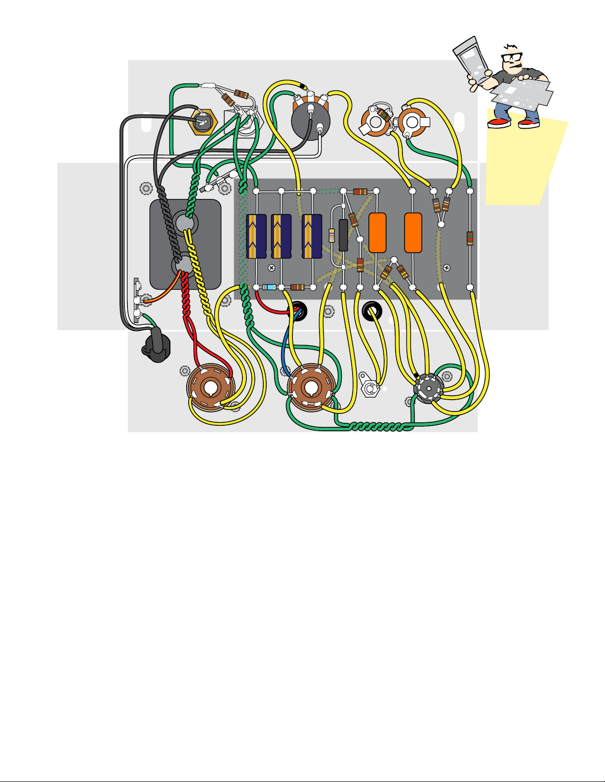
Complete wiring diagram
Our diagrams
show a flat
view of the
metal chassis
Here’s the complete 5F1 wiring
When you’ve finished the kit, you’ll have connected all the
parts shown in this wiring diagram. If it looks complex now,
don’t worry; we’ll start at the very beginning and do this
one step at a time.
Your amp-building skills will get stronger with each step!
stewmac.com 9 © 2018 StewMac
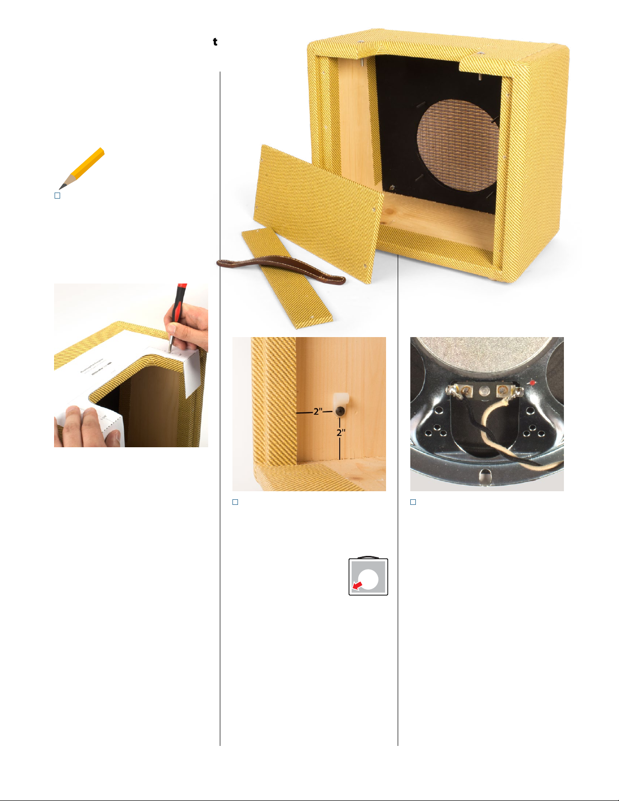
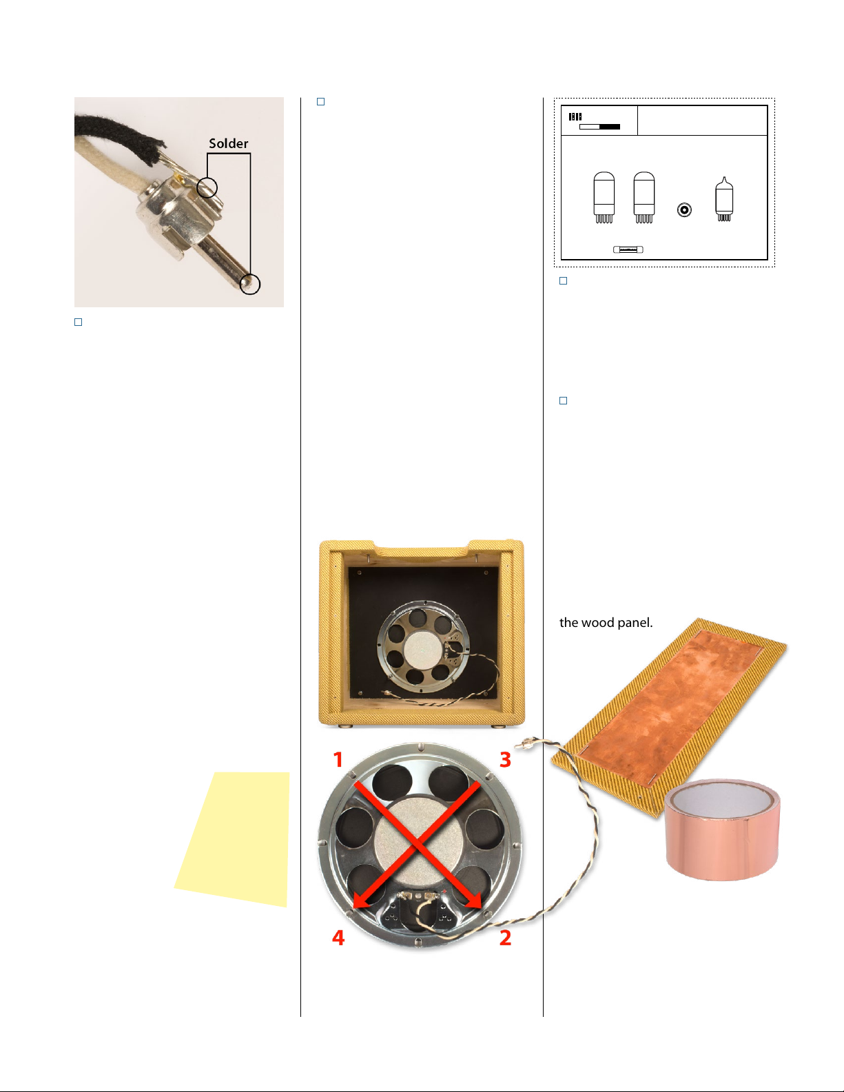
STEP 3
Solder the speaker leads
The speaker leads are black and white
wires with vintage push-back insu-
lation. Twist them together to keep
them neat.
Push the insulation back 3/8" and in-
sert the white lead into the speaker’s
positive terminal and the black lead
through the negative terminal.
Before soldering these leads, place
a business card or other protection
under the terminals to prevent sol-
der dripping onto the speaker cone.
Solder the two leads to the speaker
terminals. See “Tips for great solder-
ing” on page 16.
Prepare the cabinet for mounting the
amp chassis by first removing the two
back panels.
Remove the leather handle and set
it aside with its mounting hardware.
STEP 1
Drill two holes in the cabinet
Two 10-32 x 1.5" machine screws hold
the metal chassis inside the top of the
cabinet. The mounting hole template
on page 31 shows where to drill the
holes for these two screws.
The holes you're about to drill line
up with holes on the chassis, to the
right and left of the print control area.
Compare this template to the mount-
ing holes in the chassis, and you’ll see
how these holes line up.
Cut out the gray area and fold the
template on the dotted lines. Center
it over the control panel cutaway,
aligning it with the back edge. Tape
it in place.
Press a sharp awl through the tem-
plate at the screw locations to create
a starter hole for drilling.
Drill two 3/16" holes through the
top of the cabinet, keeping the drill
square to the surface.
Reinstall the leather handle.
Start by prepping the cabinet
Back
Here
Check off each
completed step
STEP 2
Mount the power cord clamp
Drill a 5/64" pilot hole to mount the
nylon cable clamp. Locate the clamp
on the left wall of the cab-
inet, near the lower-left
corner as seen from the
back, 2" from the bottom.
Don’t drill through the
cabinet! Use a piece of masking tape
on your drill bit to mark the depth, or
use a StewMac Depth-stop Drill Bit
(item #1712).
Use the black cable clamp screw to
mount the cable clamp. You’ll secure
the power cord with this clamp later,
during final assembly.
stewmac.com 10 © 2018 StewMac
STEP 6
Glue the tube placement chart
Cut out the tube replacement chart
on page 35. Put a thin coat of glue or
contact cement on the back and glue
it to the inside wall of the cabinet.
STEP 7
Optional copper shielding
If you prefer extra shielding on your
amp, apply copper shielding tape
(item #0028) on the top back panel,
covering the exposed wood. This
helps shield the circuit from unwant-
ed interference caused by other
electrical devices.
Because this tape’s adhesive will be
subjected to heat from the tubes, it’s
a good idea to staple the corners to
the wood panel.
STEP 5
Install the speaker
Remove the nuts from the four
speaker mounting screws. Carefully
slide the speaker onto the mounting
screws until it’s flush with the front
panel.
Install the four speaker mounting
nuts so they’re lightly touching the
speaker frame.
Do not tighten the nuts in a circular
pattern around the speaker, because
this can warp the speaker frame.
Instead tighten one nut with a quarter
turn so it’s just snug, then do the same
to the opposite side. Then snug the
third nut and fourth. Repeat this criss-
cross pattern of quarter-turns until all
four nuts have had one full turn. This
will give proper tension to compress
the speaker gasket. Overtightening
can warp the frame, damage the cone,
and cause unwanted distortion.
STEP 4
Solder the speaker plug
Push the insulation back 3/8" at the
other end of the leads. Insert the
white positive lead into the center
post of the speaker plug until it reach-
es the tip. Solder this lead in place by
heating the tip and feeding solder
through the small hole at the end of
the tip. Give the solder time to cool
before soldering the negative lead.
Use wire cutters to trim the black
negative lead so its end lines up with
the edge of the speaker plug’s cup.
Solder it to the outside of the cup as
shown above.
Don’t leave any solder on the outside
of the plug tip, or it won’t fit into the
jack.
This criss-cross pattern
keeps the speaker frame
flat against the cabinet.
Tightening in a circular
pattern makes it warp.
Prepping the cabinet
’57 MINI TWEED 5W
ORIGINAL 5F1 CIRCUIT
StewMac®
ICON KITS
Use only 1-amp slow-blow fuse.
DANGER: Unplug the amp before changing tubes.
Tube locations from left to right:
5Y3 6V6 12AX7
5Y3 6V6 12AX7
(ECC83S)
Speaker
jack

stewmac.com 11 © 2018 StewMac
The components will be soldered to
the eyelet board. The blank piece of
fiberboard is an insulator to keep the
eyelet board from touching the metal
chassis.
Two bolts hold the eyelet and insu-
lator boards to the chassis. The first
step in preparing these boards is to
drill mounting holes for these bolts.
STEP 8
Drill two holes in the boards
Place the insulator board behind the
eyelet board, aligning the two boards
so the edges are flush. Tape them
together with masking tape to keep
them aligned for drilling.
Position the taped boards inside the
chassis as shown above, with a gap
of roughly 1/4" between the boards
and the top of the chassis. The ends
of the boards are flush against the side
of the chassis.
Holding the boards in place, turn
the chassis so you can see the two
mounting holes. Using a sharp pen-
cil through the holes, mark the hole
locations onto the insulator board.
Prepping the boards
Drill the 5/32" mounting holes
through the pair of boards. Separate
the boards and set the insulator aside
for later.
STEP 9
Number the eyelets and holes
These instructions will refer to the
eyelets and holes by number. Use a
pencil to mark these numbers onto
your eyelet board:
12
13
14
15 16 17 18 19 20 21 22 23 24 25 26
2
1345678910 11

stewmac.com 12 © 2018 StewMac
Power Transformer
Output Transformer
5Y3 6V6 12AX7
4
3
2
1
8
7
6
5
4
3
2
1
8
7
6
5
6
4
3
2
1
9
8
7
5
SPEAKER JACK
Transformers
are outside
Terminals
go under
transformer
mounting
nuts
Tube mounts and clips are outside
Snip
Wrap
Solder
STEP 10
Prep two terminal strips
With a wire cutter, snip the mounting
holes on the three-lug terminals as
pictured. Cut two 1" pieces of green
wire and remove the insulation. Wrap
and solder the wires to the terminals,
electrically connecting all three lugs.
These are used as grounding strips.
STEP 11
Mount the power transformer
The power transformer has nine leads
color-coded in four pairs, plus a single
red/yellow striped lead. Twist the
same-color pairs together. Feed the
leads into the chassis through the
large hole in the chassis.
Uncover the mounting bolts and
install the transformer on the outside
of the chassis, with four 8-32 locknuts
inside. Mount the two grounding
strips at the corners as shown.
Installing the chassis-mounted components
STEP 12
Install two rubber grommets
Squeeze these into the two holes as
shown. These provide strain relief for
the transformer wires that will pass
through the metal chassis.
STEP 13
Mount the output transformer
The output transformer has red, blue
and yellow leads. Thread the red and
blue leads through one rubber grom-
met as shown, and the yellow lead
through the other grommet.
Using two 8-32 x 1/4" machine screws,
mount the transformerto the outside
of the chassis.
STEP 14
Install the speaker output jack
Mount the speaker jack to the chassis
with the large washer on the outside.
STEP 15
5Y3 tube socket + tension clip
The sockets for the 5Y3 and 6V6
tubes are identical, so you can use
either of the two for this step. Orient
the socket so pin 1 is nearest the open
side of the chassis. Use two 4-40 x 3/8"
machine screws to mount the socket
outside of the chassis. Include a ten-
sion clip on the outside to support
the tube.
STEP 16
6V6 tube socket + tension clip
Mount the 6V6 tube socket in the
same way as the 5Y3 socket.
STEP 17
12AX7 tube socket
With two 4-40 x 1/4" machine screws,
mount the 12AX7 socket. Position the
socket so pin 3 is toward the open side
of the chassis.
stewmac.com 13 © 2018 StewMac
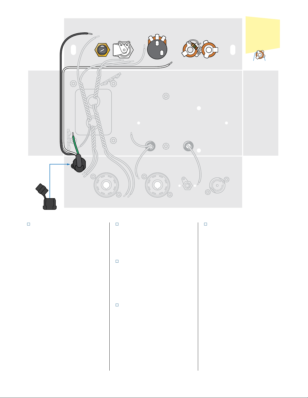
STEP 18
Add the power cord + strain relief
Strip away the power cord’s outer
insulation to reveal 7-1/2" of the three
leads inside.
Trim the black lead to 5".
Trim the green lead to 3".
Leave the white lead 7-1/2" long.
Pull the power cord leads through the
hole in the chassis and secure with the
black strain relief.
The strain relief is a tight fit. Use pliers
to squeeze it onto the power cord out-
side the chassis, and keep squeezing
to fit it into the mount hole.
STEP 19
Install the fuse socket
Mount the fuse socket so its side lug
is facing the open side of the chassis.
This makes it easier to solder later.
STEP 20
Install the pilot lamp socket
Mount the socket by screwing the
lens from the outside into the socket
assembly. Turn the arm supporting
the lamp toward the fuse.
STEP 21
Install the volume pot
A small metal tab protrudes from the
face of the pot. Bend and snap this
off, so the pot can mount flush to the
surface of the chassis.
Mount the pot so its three lugs face
out toward the chassis opening.
STEP 22
Install two jacks + 1M resistor
Add the two input jacks. Turn the
jacks so the right lug of jack 1 is close
to the center lug of jack 2 as pictured.
Run one lead of the 1M resistor
through the right lug of jack 1 and
through the center lug of jack 2.
Make sure the lead won’t be in the
way when an instrument cable is
plugged in.
This resistor connects to all three
lugs of jack 1. Run the resistor’s other
lead through the left lug of jack 1 and
connect it to the center lug of jack 1.
Don’t solder these connections yet.
5Y3 6V6 12AX7SPEAKER JACK
JACK 1VOLUME POTLAMPFUSE JACK 2
4
3
2
1
8
7
6
5
6
4
3
2
1
9
8
7
5
4
3
2
1
8
7
6
5
LEFT+RIGHT
refer to however
the parts are
shown on the
diagram
RIGHTLEFT
stewmac.com 14 © 2018 StewMac
5Y3 6V6 12AX7SPEAKER JACK
JACK 1VOLUME POTLAMPFUSE JACK 2
6
4
3
2
1
9
8
7
5
4
3
2
1
8
7
6
5
4
3
2
1
8
7
6
5
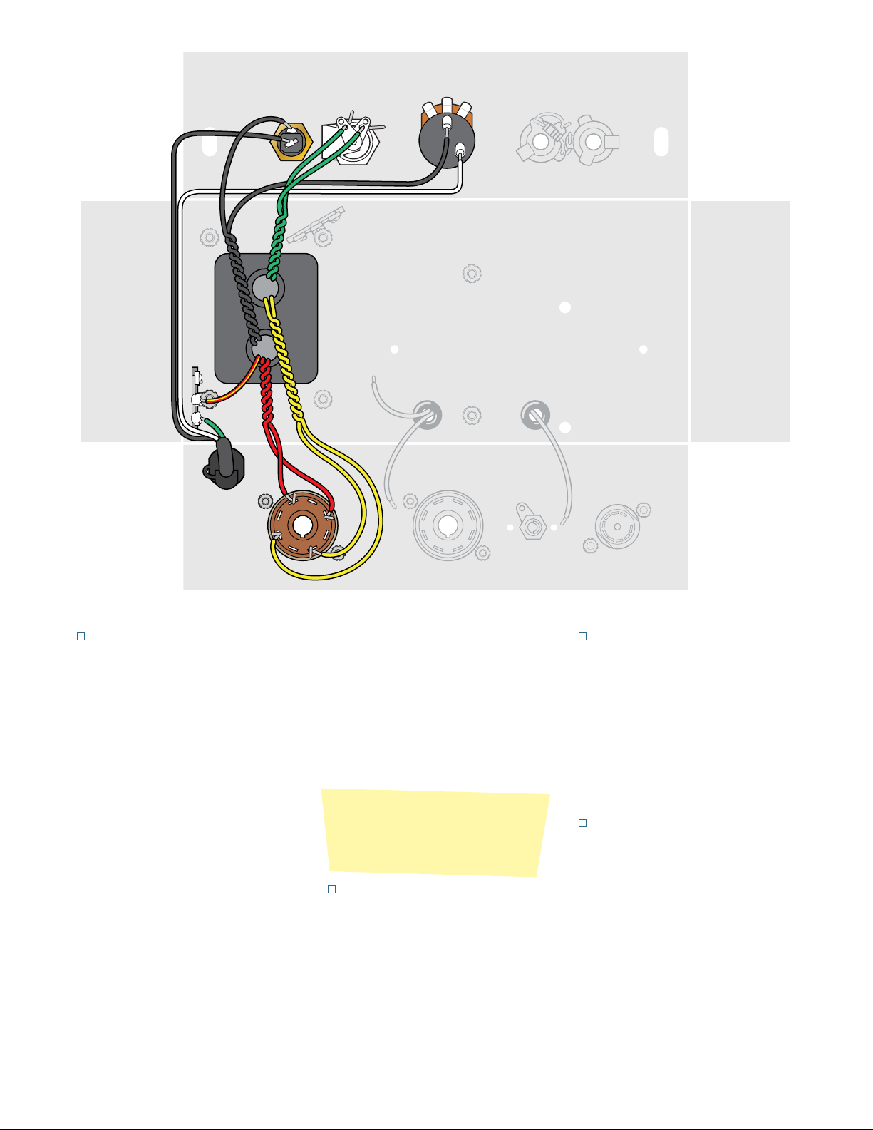
STEP 23
Connect the power cord leads
Route the power cord’s white lead
around the edge of the chassis to the
volume pot. Solder it to the lower
right switch lug on the back of the pot.
Solder the power cord’s black wire to
the center/back lug of the fuse socket.
Danger: Soldering this lead to the
side lug of the fuse socket will create
a shock hazard.
Solder the power cord’s green ground
wire onto the nearby grounding strip.
uSTEP 24
Power transformer black leads
Run one black lead from the power
transformer to the side lug of the fuse
socket. Trim it to fit and solder it.
Trim and solder the other black lead to
the remaining switch lug on the back
of the volume pot.
uSTEP 25
Power transformer green leads
Run the two green wires from the
power transformer to the lugs on
the pilot lamp socket (either wire can
go to either lug). Trim these wires to
length and wrap them onto the lugs.
Don’t solder these connections yet.
STEP 26
Power transformer
red/yellow lead
Trim the power transformer’s red/
yellow lead to an appropriate length
and solder it to the 3-lug terminal
strip along with the green wire from
the power cord.
STEP 27
Power transformer red leads
Trim the power transformer’s red
leads to an appropriate length and
wrap one lead onto pin 4 of the 5Y3
socket.
Wrap the other red lead onto pin 6 of
the same socket. Don’t solder these
red leads yet.
STEP 2 8
Power transformer yellow leads
Trim the power transformer’s yellow
leads to an appropriate length. Wrap
one yellow lead onto pin 2 of the 5Y3
socket.
Wrap the other yellow lead onto pin 8
of the same socket. Don’t solder these
yellow leads yet.
Despite being green, these aren’t
ground wires. They power the pilot
lamp and tube heater filaments.
stewmac.com 15 © 2018 StewMac
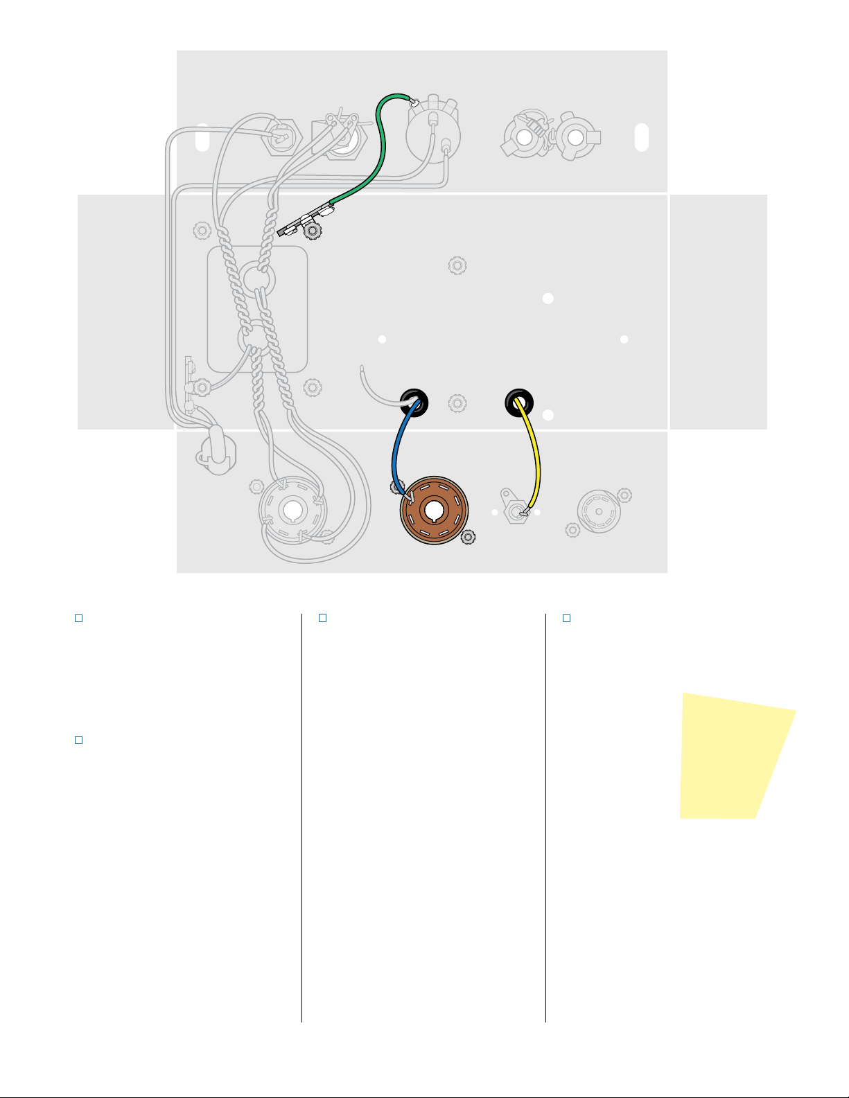
STEP 29
Output transformer blue lead
Trim the blue wire from the output
transformer to a suitable length and
wrap it onto pin 3 of the 6V6 socket.
Don’t solder this connection yet.
STEP 30
Output transformer yellow lead
Trim the yellow wire from the output
transformer to an appropriate length
and wrap it onto the center lug of the
speaker output jack.
5Y3 6V6 12AX7SPEAKER JACK
JACK 1VOLUME POTLAMPFUSE JACK 2
4
3
2
1
8
7
6
5
6
4
3
2
1
9
8
7
5
4
3
2
1
8
7
6
5
STEP 31
Ground the volume pot
Cut a 3" piece of green wire and solder
it to the left lug of the volume pot as
pictured.
Wrap and solder the other end of this
wire to the three-lug grounding strip
near the pilot lamp.
A wire between two parts like this is
called a jumper. Don’t cut this piece
too long, because there’s just enough
green wire to create all the jumpers
you’re going to need.
STEP 32
Inspect and double-check
This is a good time to step away from
the project for a few minutes and take
a break.
When you’re ready
to go at it again,
carefully review
every connection
you’ve made so far.
When everything
checks out, you're ready to move on
to the eyelet board.
Be suspicious
Assume there's
a mistake and
you’re the one
who’ll find it!
stewmac.com 16 © 2018 StewMac
Wrap
Don’t solder the components as they
go onto the eyelet board. Instead
wrap all the parts onto the board,
bending their leads tightly so the
parts stay in place without solder.
Don’t think of solder as glue
Good mechanical connections make
good electrical connections. Solder’s
job is to finalize an already good joint,
not to hold the parts on the board.
Inspect
When all the parts are in place, stop
and inspect. Go back over every step.
Careful inspection is the best way to
make sure your amp works the first
time you turn it on.
Make the specs visible
Attach components with the specs
facing out so you can read them. Many
builders also align resistor bands to
read in the same direction.
Solder
Solder each connection point only
once. Reheating to add another part
makes a messy, faulty solder joint.
Use the soldering tips below to get
professional results.
How much insulation to strip?
With plastic insulation, strip 3/8" from
the wire ends. Push-back wire works
best when you strip away about 1/4"
of the cloth wrap.
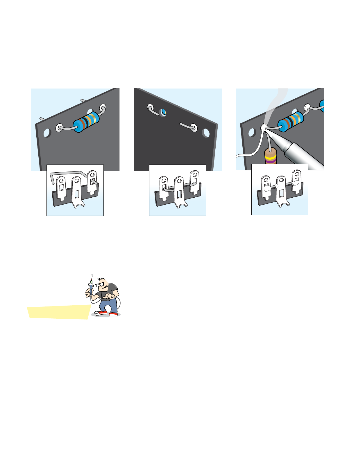
How to wrap and solder the eyelet board
Put the lead through
the eyelet or lug
Bend it tight against
the opposite side
Solder after
all the parts
are in place
Trim excess wire
Tips for great soldering
nWrap the leads tightly for good
electrical contact before soldering.
nMelt a small amount of solder onto
the tip of the iron (“tinning” the iron).
Hold the tip against the connection
until the connection reaches solder-
ing temperature. This should take just
a few seconds.
You should also tin component leads,
like coating multi-strand wires to help
the solder flow for a more solid joint.
nKeep your soldering tip clean by
wiping it often on a damp sponge.
Also keep it tinned by occasionally
melting a little solder onto it.
nFeed solder to the connection, not
to the iron. Stop feeding solder once
the eyelet is filled. Keep the iron on
the connection for a second longer;
this pause gives time for all of the flux
to cook out of the joint.
nDon’t blow on the hot solder or
touch anything until the joint has
cooled completely. A good solder
joint is shiny — a sign that it was left
to cool undisturbed.
nAfter the joint has cooled, trim away
the excess wires.
nPlan so each joint is only soldered
once. Resoldered joints are messy and
more likely to fail.

stewmac.com 17 © 2018 StewMac
12
13
14
15 16 17 18 19 20 21 22 23 24 25 26
2
1345678910 11
Dotted wires are on
back of board
Dotted wires are on
back of board
.022μf
STEP 33
Install a 1.5K resistor
+ two jumpers
Wrap a 1.5K resistor’s leads onto eye-
lets 11 and 26. These leads aren’t long
enough to wrap onto the back of the
board, but masking tape will hold this
resistor in position temporarily.
Resistors have no polarity, so they can
be installed in either direction.
Cut a 3" piece of green wire and wrap
one end of this jumper onto eyelet 11.
Cut and wrap a 3" yellow jumper onto
eyelet 26.
STEP 34
Add two 68K resistors
+ three jumpers
Place one 68K resistor between
eyelets 10 and 13, and the other 68K
resistor between 9 and 13.
Cut a 2" yellow jumper and wrap it
onto eyelet 9. Wrap a 4" yellow jumper
onto eyelet 10.
Turn the board over and add a 5" yel-
low jumper from the back at eyelet
13. Run this jumper to the front of the
board through hole 25 and pull it tight
to keep it in place.
STEP 35
Install a .022μF cap + one jumper
Wrap one of the .022μF Orange Drop
capacitors between eyelets 8 and 24.
This cap is not polarized, so it can be
installed in either direction.
Add a 4" yellow jumper to eyelet 8.
STEP 36
Add two 100K resistors
+ one jumper
Place one 100K resistor between eye-
lets 14 and 24.
Attach one 3" yellow jumper to eyelet
24 with the capacitor and resistor
leads.
Attach the other 100K resistor be-
tween eyelets 22 and 14.
STEP 37
Wrap a jumper wire onto
the back of the board
Turn the board over and attach a
2-1/4" yellow jumper between eyelets
14 and 18.
Wrapping parts onto the eyelet board
For neat looking wiring, use wire
strippers to trim 1/4" of the insulation
from the ends of the push-back wire.

stewmac.com 18 © 2018 StewMac
12
13
14
15 16 17 18 19 20 21 22 23 24 25 26
2
1345678910 11
.022μf
+
25μF
STEP 38
Install a .022μF capacitor
+ one jumper
Wrap the second .022μF 600V Or-
ange Drop cap between eyelets 7
and 22 (not polarized; okay in either
direction).
Cut a 2" yellow jumper and add it to
eyelet 22.
STEP 39
Add a 220K resistor
+ one jumper
Add the 220K resistor between eye-
lets 6 and 7.
Turn the board over and add a 5"
yellow jumper at eyelet 7. Run the
jumper up through hole 19 and pull
it tight so it stays in place.
STEP 40
Add a 22K resistor
+ one jumper
Attach a 22K resistor between eyelets
21 and 12.
Add a 1-1/2" yellow jumper to eyelet
21.
STEP 41
Add a 1.5K resistor
+ one jumper
Add the other 1.5K resistor between
eyelets 6 and 12.
Flip the board and add a 5" yellow
jumper to eyelet 12. Run the jumper
up through hole 23 and pull it tight.
STEP 42
Install a 25μF cap + a 470Ω
resistor, soldered together
Wrap the leads from the 25μF 50V
capacitor around the leads on the
470Ω resistor.
Note the polarity of the capacitor.
Install this resistor/capacitor assembly
between eyelets 6 and 20, making
sure the capacitor’s negative lead
goes to eyelet 6.
Add a 2-1/2" yellow jumper wire at
eyelet 20.
20
6
+
25μF
Positive Negative
Table of contents
Other StewMac Amplifier manuals


Popular Amplifier manuals by other brands

MCM Custom Audio
MCM Custom Audio MPA-20 Operation manual

Audio Research
Audio Research LS5 owner's manual

Goldmund
Goldmund MIMESIS 24 user manual

Crestron
Crestron 4K DigitalMedia 3-Series Supplemental guide

Digital Acoustics
Digital Acoustics IP7-FD Reference manual

Onkyo
Onkyo Integra P-388F Service manual


