StewMac '81 BRIT-800 User manual
ASSEMBLY INSTRUCTIONS
With loads of
helpful tips!
’81 BRIT-800 50W
AMPLIFIER KIT
ORIGINAL BRITISH CIRCUIT
The king of shred

stewmac.com 2 © 2019 StewMac
Contents
About this iconic amp ............................................ 1
...................................................
2
Parts list ........................................................... 3
Tools and supplies ................................................ 5
Amp voltages are seriously dangerous! .......................... 6
How to use a snuffer stick ........................................ 6
How to read resistor values ...................................... 7
Capacitor values .................................................. 7
Complete wiring diagram ........................................ 8
Prepping the turret board ........................................ 9
Tips for great soldering .......................................... 9
Installing the chassis-mounted components ................... 11
Wrapping parts onto the turret board .......................... 27
Soldering components to turret board ......................... 33
Installing the turret board in the chassis ....................... 35
Installing parts and preparing for testing ...................... 40
Testing and troubleshooting .................................... 41
Final assembly ................................................... 44
Tips for using this amp .......................................... 44
Photograph of completely wired chassis ....................... 45
Learning more: secrets revealed in the schematic .............. 46
Circuit schematic ................................................ 47
More iconic amp kits from StewMac . . . . . . . . . . . . . . . . . . . . . . . . . . . . . 48
Full page wiring diagram ........................................ 50
Tube replacement chart ......................................... 51
COPYRIGHT WARNING
This material is protected by copyright and has been created by and solely for the purposes of StewMac.
You may not sell, alter or further reproduce any part of this material, or distribute it to any other per-
son. Where provided to you in electronic format, you may only print from it for your own private use.
Failure to comply with the terms of this warning exposes you to legal action for copyright infringement.
How to build this kit!

stewmac.com 1 © 2019 StewMac
’81 BRIT-800 50W
AMPLIFIER KIT ORIGINAL BRITISH CIRCUIT
This amp is an ICON
This is the defining British circuit that dominated the '80s.
This 50W giant created your favorite heavy rock and metal albums. Used
by Slayer and Pixies, and recorded on early Metallica albums, this circuit
produces that screaming guitar tone that your mother despises. With
solid-state rectification there's no sag, and the distortion created by this
ciruit is way more about treble than mids or bass.
StewMac ICON KITS bring classics that are no longer made, or are simply
unaffordable, within reach. And the best part is you get to build them with
your own hands.
We give painstaking attention to parts selection, authentic materials, and
instantly recognizable details—everything that makes the originals so sought
after.
Build it with StewMac
These immersive instructions walk you through every step of creating your
’81 Brit-800. And you’ll learn a lot, gaining a deep knowledge of your amp’s
inner workings.
Follow our steps closely for safety, too: we’ve carefully laid out a path that
even newcomers can follow in handling electrical components.
Building an amp can seem daunting, but nobody makes it easier than
StewMac. Watch for helpful tips along the way, too—we’re here to help!
Let’s get building!
Iconic British tone
is now in your hands
Be excited!
Your new StewMac ’81 Brit-800 will be a blast
to play through and even more fun to build.
This amp is renowned for its saturated lead
tone that is bright and tight, with an in-your-
face crunch. You can scoop the mids and
have a completely different tone in an instant.
Often overlooked, the clean tone is rich,
full, and gives this amp unrivaled presence
onstage. This amp fueled the sound of ’80s
heavy metal.

stewmac.com 2 © 2019 StewMac
Here’s how to build this amp!
Wiring goes like this:
1. First, you’ll wrap the leads, connecting them without solder.
2. Then double-check all the connections. Don’t rush!
3. When everything checks out, it's time to solder.
The numbered steps tell you when.
Get the turret board ready,
starting at Step
1
on page
9
.
You’ll prep the metal chassis
too.
Learn more:
You don’t need to read the schematic, but it’s fun!
See how your guitar’s signal gets processed into sound
on page 47.
Sort your components by type, using the parts list.
Quick look:
OutputGain Processing Gain GainProcessing Negative feedback
See page
9
#10735 © 2019 StewMac
Ground
JackTransformer Preamptube
plate
grid
cathode
Power tube
grid
plate
cathode
screen
Capacitor Electrolytic Cap. Diode
Resistor Potentiometers Rectifier tube
plate cathode
filament
plate
Shielded
cable ’81 BRIT-80050W
ORIGINAL BRITISH CIRCUIT
Output
Gain
Gain
Gain
Power
Processing Processing
Power
Negative Feedback

stewmac.com 3 © 2019 StewMac
Hardware
r (4) M6 machine screw, 30mm
r (4) M6 cagenut
r (12) 8-32 machine screw, 3/8"
r (12) 8-32 locknut
r (6) 6-32 locknut
r (4) 4-40 threaded standoff, 1/2"
r (10) 4-40 machine screw, 3/8"
r (14) 4-40 machine screw, 1/4"
r (16) 4-40 locknut
r (3) Filter cap mounting clamp
r (1) Small rubber grommet
r (4) Large rubber grommet
Capacitors & diodes
r (1) 10pF 500V silver mica
r (1) 47pF 500V silver mica
r (3) 500pF 500V silver mica
r (1) .001μF (1nF) 630V Mojo Dijon
r (7) .022μF (22nF) 630V Mojo Dijon
r (2) .01μF (10nF) 630V Mojo Dijon
r (1) .68μF 630V Mojo Dijon
r (2) 8μF 150V Sprague Atom
r (3) 50μF+50μF 500V electrolytic filter cap
r (1) 1N4007 1000V rectifier diode
r (2) 1N5408 1000V rectifier diode
r (1) Cabinet
r (1) Chassis
r (1) Turret board
r (1) Faceplate/backplate set
Resistors
r (1) 470Ω .5W carbon composite
r (2) 820Ω .5W carbon composite
r (1) 2.7K .5W carbon composite
r (1) 4.7K .5W carbon composite
r (2) 5.1K .5W carbon composite
r (1) 10K .5W carbon composite
r (1) 15K .5W carbon composite
r (1) 33K .5W carbon composite
r (1) 47K .5W carbon composite
r (1) 56K .5W carbon composite
r (1) 82K .5W carbon composite
r (6) 100K .5W carbon composite
r (2) 220K .5W carbon composite
r (3) 470K .5W carbon composite
r (3) 1M .5W carbon composite
r (2) 220K 2W metal oxide
r (2) 10K 5W ceramic
r (1) 1K 5W ceramic
5W 1K
5W 10K
+
8µF
510K4710
.01μF
.68μF
.001μF
Green Brown Red Gold
Brown Green Orange Gold
Red Red Yellow Gold
Yellow Violet Brown Gold
Gray Red Brown Gold
Red Violet Red Gold
Yellow Violet Red Gold
Brown Black Orange Gold
Orange Orange Orange Gold
Yellow Violet Orange Gold
Yellow Violet Yellow Gold
Brown Black Green Gold
A magnifier helps!
Green Blue Orange Gold
Gray Red Orange Gold
Brown Black Yellow Gold
Red Red Yellow Gold
50μF + 50μF
500V
+
.022μF
Parts list

stewmac.com 4 © 2019 StewMac
Parts list
Tubes, lamps, fuses, and sockets
r (4) Four-lug jack
r (3) Nine-pin tube socket
r (3) Shield for nine-pin tube socket
r (2) Eight-pin tube socket
r (2) Spring retainer for eight-pin socket
r (3) 12AX7 preamp tube (also called ECC83S)
r (2) EL34 power tube
r (2) Fuse socket
r (1) Fuse (3 amp, slow blow)
r (1) Fuse (1/2 amp, slow blow)
r (1) Power inlet
Control pots and more
r (1) 10KL bias pot
r (3) 1M control pot (A-audio taper)
r (1) 5K control pot (L-linear taper)
r (1) 25K control pot (L-linear taper)
r (1) 250K control pot (L-linear taper)
r (1) Impedance selector switch
r (1) Voltage selector switch
r (1) Power switch (5 lugs)
r (1) Standby switch (4 lugs)
r (6) Knob
r (2) Three-lug terminal strip
r (2) Ground tab
r (1) Power cord
Wire
r (1) White wire
r (1) Green wire
r (1) Shielded wire
r (1) White heater wire
r (1) Black heater wire
r (1) Bare copper bus wire
Transformers
r (1) Power transformer
r (1) Output transformer
r (1) Filter choke
Heat-shrink tubing
r(2) 1/8” diameter (2-1/2” length)
12AX7 EL34
4
3
2
1
8
7
6
5
6
4
3
2
1
9
8
7
5
1
M
A
5
K
2
5
K
2
5
0
K
1
0
K
L
4
Ω
8
Ω
1
6
Ω
1
1
0
V
2
2
0
V
2
3
0
V

stewmac.com 5 © 2019 StewMac
#0531
StewMac
Solder Monster
#3000
Guitar Tech
Screwdriver Set
#1606
Wire Stripper
#1607
Wire Cutter
#0501
Solomon SL-30
Soldering Station
#1609
Round Nose
Bending Pliers #0505
Kester
Pocket-Pak
Solder
StewMac’s Solder Monster
holds parts while you solder
Tools and supplies
Required Phillips screwdrivers, #1 and #2
Item #3000 Guitar Tech Screwdriver Set
Needle nose pliers
Item #1610 Long Nose Pliers
Wire cutter
Item #1607 Wire Cutter
Wire stripper
Item #1606 Wire Stripper
Soldering iron (preferably 40W)
Item #0501 Solomon SL-30 Soldering Station
Solder (at least one Pocket-Pak)
Item #0505 Kester Pocket-Pak Solder
Solder sucker
Item #0503 Solomon Solder Sucker
Drill with a 5/32" bit
For mounting turret board and filter cap
Ruler
Item #4905 StewMac Shop Rule
Digital multimeter
Item #3618 Fieldpiece Pocket Multimeter
Snuffer stick (bleed resistor)
Item #1552 Snuffer Stick
Pencil
Wooden chopsticks
Glue
Wood glue, white glue, or
contact cement for gluing a
paper label inside the cabinet
Butane lighter or matches
For heating heat-shrink tubing
Contact cement
Helpful Round nose bending pliers
Item #1609 Round Nose Bending Pliers
Solder wick
Item #0504 Solder Wick, 5-foot roll
Soldering aids
Item #0521 StewMac Soldering Aids
Soldering stand
Item #0506 Solomon Soldering Stand
Solder Monster, or helping hand tool
Item #0531 StewMac Solder Monster
Chassis stand
Item #10750 Chassis Stand
Printed circuit board vise
Scratch awl or center punch
Item #3000 Guitar Tech Screwdriver Set
Tray for loose parts
Bias meter for accurate biasing
Item #1580 VHT Tube Tester
+ Amp Bias Meter
stewmac.com 6 © 2019 StewMac
High voltage, even when unplugged
When you turn on an amp, the capacitors are designed to
take on a charge and hold it. That stored voltage is enough
to injure you seriously, or even kill you.
These components aren’t a threat until the first time you plug
the amp in. The stored electricity can be safely discharged to
ground with a snuffer stick. See how to use it below.
Once your amp has been turned on, don’t touch the wiring
with your bare hands—even after turning it off. If you need
to press on a contact, use a chopstick or Sharpie marker,
which are both non-conductive. Don’t use a pencil, because
graphite is conductive.
It’s important that you understand the dangers so you’re
working safely. Here’s how to do it right.
Wear rubber-soled shoes
Rubber soles increase the insulation
between yourself and the ground.
Take off your ring
A metal ring on your finger can
bridge a hot connection to ground.
Wear safety glasses
Rosin-core solder sometimes bubbles up, and it can spew
molten specks into the air. You don’t want molten solder in
your eyes.
It’s better not to work alone
Electrical shocks can incapacitate you, and having someone
available to call 911 can be a lifesaver.
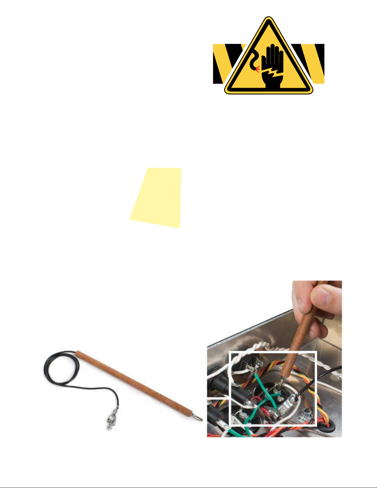
How to use a snuffer stick
To discharge a capacitor, clip the snuffer stick lead
to ground—preferably a mounting bolt on the
power transformer. Hold the tip of the stick to the
cap’s positive lead and use your multimeter to
watch the voltage drain to less than 18V.
Take breaks and stop when you’re tired
Fatigue leads to mistakes, and no one can afford mistakes
when working with electricity.
Stay suspicious
Whether it’s the first time you’ve been inside a live ampli-
fier or the 100th time, don’t become complacent. If you
discharge the caps and walk away for a few minutes, check
again for residual voltage when you return. Capacitors can
self-charge through a phenomenon known as dielectric
memory.
Check before powering on
It’s easy to forget that you a left a stray tool or wire in the
chassis. It’s also easy to forget to re-attach the speaker wire,
and that can fry an output transformer in seconds. Constant
vigilance is your friend when working on amps.
Always unplug it
Unplug the amp whenever you don’t specifically need it
plugged in. Some points are always hot when the amp’s
plugged in, even if the power switch is off. These points
include the lugs on the fuse socket, power switch, and
standby switch.
Amp voltages are seriously dangerous!
Professionals
who work on
amps take these
safety habits
very seriously

stewmac.com 7 © 2019 StewMac
A resistor’s value—the amount of resistance it creates—is
rated in ohms (Ω). Larger ohm values mean more resistance.
For example, a 100Ω resistor creates ten times as much re-
sistance as a 10Ω resistor.
The resistors used in amplifiers are too small to have value
numbers printed on them. Instead, a system of colored
bands tells their values. The key to reading these bands is
provided below. However, an easier way to decode these
bands is to download one of the many smartphone apps
for this purpose.
One band will be the nearest to an end of the resistor. That
band tells the first value. Combine it with the value of band
2 to get a two-digit number (68 in our example below).
Multiply that number by band 3 (68 x 1,000 = 68,000). Thou-
sands are represented by the letter K, so this resistor is 68K
(kilo-ohms, or KΩ).
If there is a fourth band, it will be either silver or gold. This
indicates the tolerance allowed during manufacturing. The
resistors used in this kit have a +/- 5% tolerance, represented
by a gold band 4.
A magnifying glass helps a lot. The bands on a 470Ω resistor
are yellow/violet/brown, and the bands on a 47K resistor are
yellow/violet/orange. They’re easily confused!
Can’t read the colors?
You can always use a multimeter to test a resistor’s value.
Set your meter to ohms and connect the test leads on each
side of the resistor.
Capacitor values are typically printed on the component.
The key values with caps are their capacitance and voltage.
Think of a capacitor as a container that can hold electricity.
Capacitance, measured in farads, refers to how much elec-
tricity this container can hold—its capacity. One farad (1F)
would be much too large for use in an amplifier. Caps for
amps are rated in millionths of a farad, called microfarads
(μF), or trillionths of a farad: picofarads (pF). The voltage
spec for a cap refers to how much DC voltage it can handle
at any given time.
A unique property of capacitors is that they don’t allow DC
current to flow past them, only AC current. This is important
in parts of an amplifier circuit, such as the path between a
preamp stage and a power amp stage. Here, a “coupling
capacitor" will block DC voltage, allowing only the AC guitar
signal to pass.
Filter caps
Capacitors also filter out 60Hz hum, or “ripple," after the AC
current from the wall is converted to DC. These capacitors
are called filter caps, because they filter out the ripple from a
power supply. The filter caps in this amp are the 50μf + 50μf
electrolytic can capacitors. This means that each physical
capacitor has two caps inside, each with their own positive
lug, and they share a common negative lug.
Electrolytic caps
Electrolytic capacitors contain electrolyte: a liquid or gel
that gives them a large storage capacity. Electrolytic caps
are typically polarized.
Polarized caps
Some capacitors have polarity and some don’t. It’s extremely
important to install polarized caps correctly in a circuit. The
positive lead of an electrolytic cap will be indicated by an
indented ring around one edge of the capacitor. The nega-
tive lead will often be indicated by a band of arrows pointing
to the negative lead.
Installing capacitors with the polarity backwards will make
the circuit malfunction and quickly destroy the capacitor—
even causing it to explode.
Band 1 Band 2 Band 3 Band 4
1st Digit 2nd Digit Multiplier Tolerance
6 8 x1,000 +/- 5%
68K +/- 5%
K=1,000
Blue
Read this band first (closest to an end)
Gray Orange Gold
BLACK 0 0 1 None +/- 20%
BROWN 1 1 10
RED 2 2 100
ORANGE 3 3 1,000
YELLOW 4 4 10,000
GREEN 5 5 100,000
BLUE 6 6 1,000,000
VIOLET 7 7
GRAY 8 8 0.01 +/- 10% SILVER
WHITE 9 9 0.1 +/- 5% GOLD
50μF + 50μF
500V
NegativePositive
+
8μF
How to read resistor values Capacitor values
stewmac.com 8 © 2019 StewMac
V5
EL34 V4
EL34
POWER STANDBY PRESENCE BASS MIDDLE TREBLE MASTER
VOLUME
PREAMP
VOLUME
INPUT
(NORMAL)
H.T. FUSE
V3
12A X7 V2
12A X7 V1
12A X7
SPEAKER EXTENSION
SPEAKER
VOLTAGE
SELECTOR
IMPENDANCE
SELECTOR
FILTER CAP 3
FILTER CAP 2FILTER CAP 1
MAINS INPUT MAINS
FUSE
1
M
A
1
2
4
3
1
2
4
3
1
M
A
1
M
A
2
5
0
K
L
2
5
K
L
1
M
A
5
K
L
4
3
2
1
8
7
6
5
4
3
2
1
8
7
6
5
3
6
5
2
1
4
6
4
3
2
1
9
8
7
5
6
4
3
2
1
9
8
7
5
6
4
3
2
1
9
8
7
5
D
-
-
D
-
-
D
-
-
A
B
3
6
5
2
1
4
4 2
3 1
4 2
3 1
.1μF
5W 1K
5W 1K
.001μF 510K
1
29
2
26
34567
20 21
22 23 24
27
25
28
8910 11 12 13 14 15 16 17 18
34 35 36 37 38 39 40 44 45 46
33
32
31
19
30 41 42 43
.022μF
.022μF
.68μF +
500pF
500pF
.022μF
.022μF
.022μF
5W 10K
5W 10K
.022μF
.022μF
.01μF
47
+
8µF
+
8µF
10
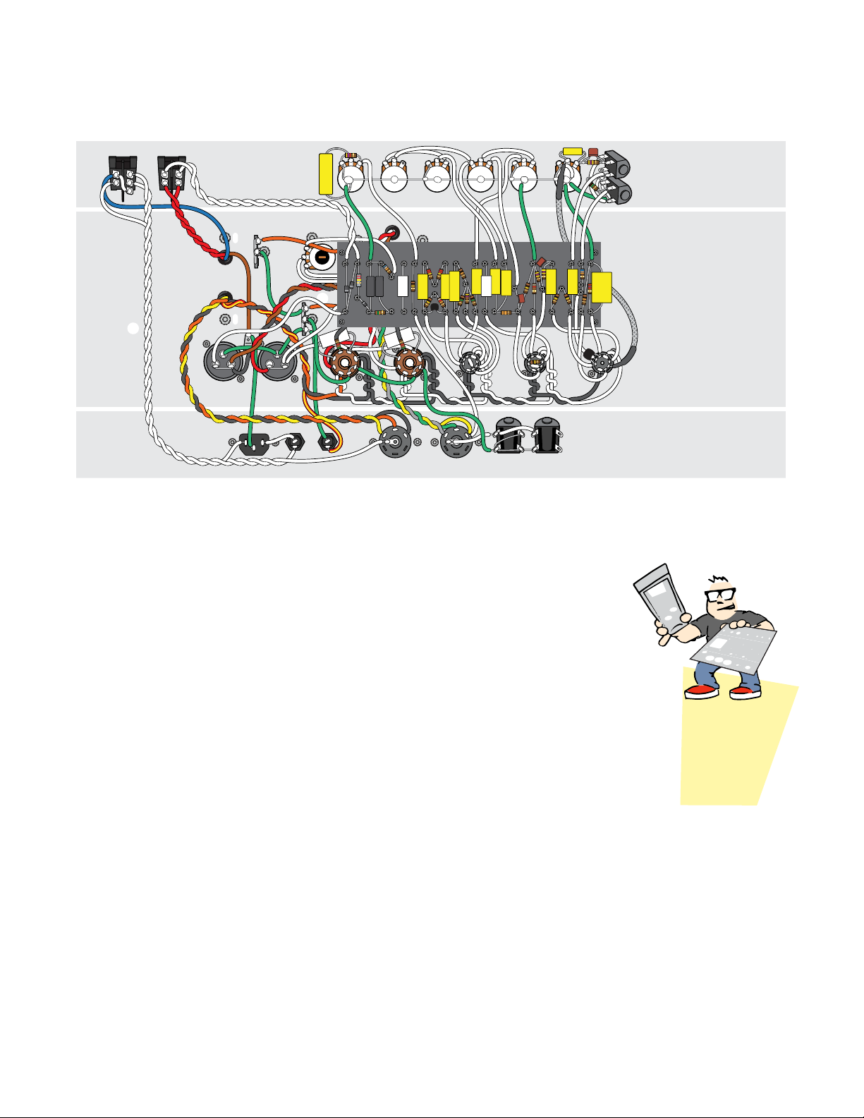
Complete wiring diagram
Our diagrams
show a flat
view of the
metal chassis
Here’s the complete Brit-800 50 wiring
When you’ve finished the kit, you’ll have connected all the
parts shown in this wiring diagram. If it looks complex now,
don’t worry; we’ll start at the very beginning and do this
one step at a time.
Your amp-building skills will get stronger with each step!

stewmac.com 9 © 2019 StewMac
Start by prepping the turret board
nWrap the leads tightly for a good
electrical contact before soldering.
Don’t use solder to “glue" loose joints.
nMelt a small amount of solder onto
the tip of the iron (“tinning" the iron).
Hold the tip against the joint for a few
seconds, until the connection reaches
soldering temperature.
Also tin component leads like multi-
strand wires to help the solder flow.
You’re ready to build!
Tips for great soldering!
STEP 1
Number the turrets
The steps refer to the turrets by num-
ber. Number the turrets on your board
by putting tape along the edges
and writing with a fine-point
marker. You’ll remove the
tape before installing
the board.
Leave the turrets in the center
of the board (#19–28) unmarked.
You can identify these turrets by
referring to the diagrams.
nKeep your soldering tip clean by
wiping it often on a damp sponge.
Keep it tinned by occasionally melting
a little solder onto it.
nFeed solder to the connection not
to the iron. Keep the iron on the con-
nection for a second longer to allow
time for all of the flux to cook out of
the joint.
nDon’t ever blow on the hot solder
or touch anything until the joint is
completely cool. A good solder joint
is shiny—a sign that it was left to cool
undisturbed.
1
29
2
26
34567
20 21
22 23 24
27
25
28
8910 11 12 13 14 15 16 17 18
34 35 36 37 38 39 40 44 45 46
33
32
31
19
30 41 42 43
nTrim away the excess wires after the
joint has cooled.
nPlan ahead so each joint is only
soldered once. Resoldered joints are
messy and more likely to fail.
nPosition the parts so their specs face
out so you can read them later. Many
builders also align resistor bands to
read in the same direction.
nHow much insulation to strip? With
plastic insulation, strip 3/8" from the
wire ends. Push-back wire works best
when you strip away about 1/4" of the
cloth wrap.
Component leads are wrapped onto
the turrets and left unsoldered while
you add other parts. This way, you can
check your work and make correc-
tions without having to redo a solder
joint. Ideally you solder a turret only
once, which is the best way to get
clean, trouble-free connections.
When it's time to solder, flow the
solder all the way around the turret.

stewmac.com 10 © 2019 StewMac
V5
EL34 V4
EL34
POWER STANDBY PRESENCE BASS MIDDLE TREBLE MASTER
VOLUME
PREAMP
VOLUME
INPUT
(NORMAL)
H.T. FUSE
V3
12AX7 V2
12AX7 V1
12AX7
SPEAKER EXTENSION
SPEAKER
VOLTAGE
SELECTOR
IMPENDANCE
SELECTOR
MAINS
FUSE
FILTER CAP 3
FILTER CAP 2FILTER CAP 1
MAINS INPUT
OUTPUT TRANSFORMER
(Mounted outside)
POWER TRANSFORMER
(Mounted outside)
FILTER CHOKE
(Mounted outside)
1
M
A
1
M
A
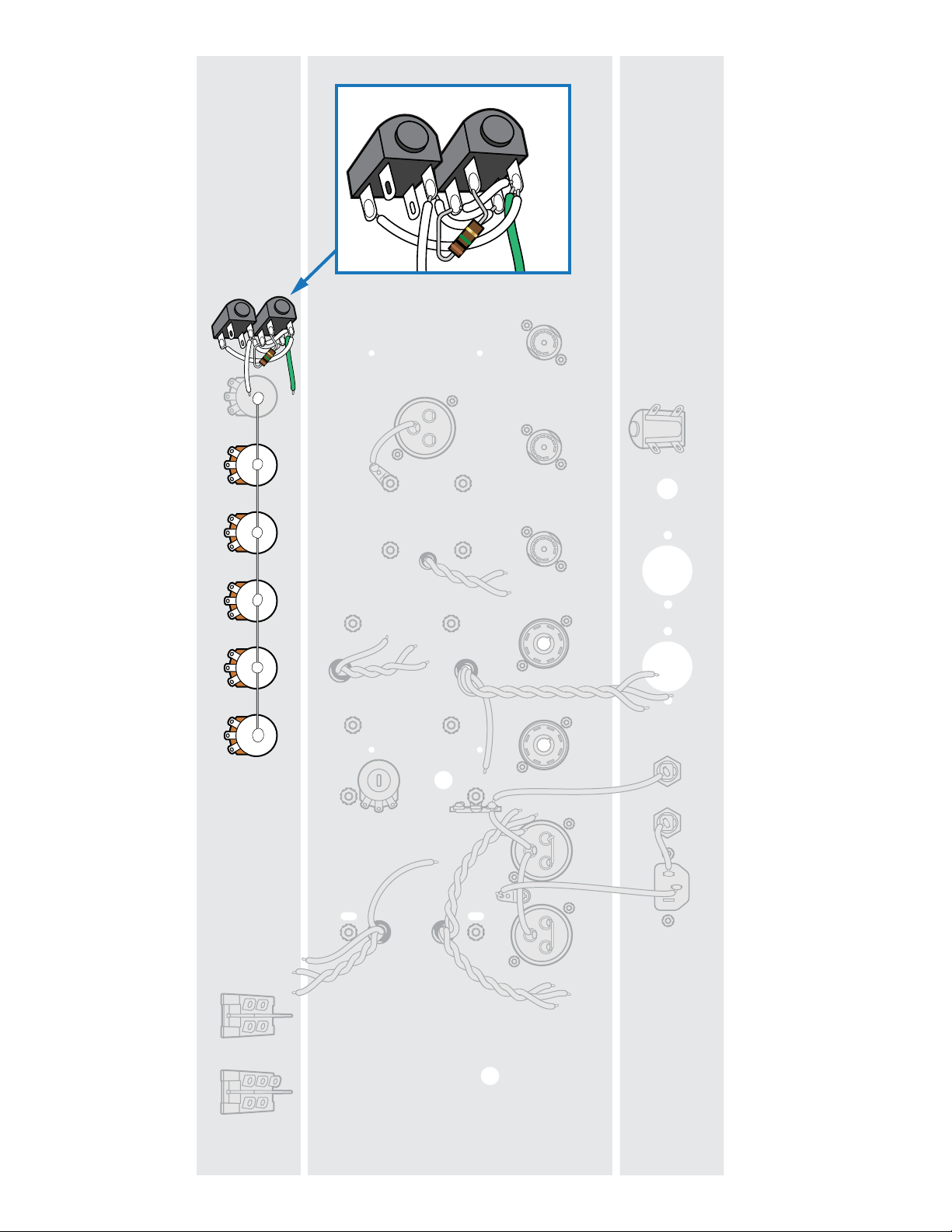
Solder three lugs
to make them a
common ground
3. Solder
1. Snip
2. Wrap

stewmac.com 11 © 2019 StewMac
Installing the chassis-mounted components
STEP 2
Mount the faceplate and backplate
Peel the protective film off the chassis,
faceplate, and backplate. Secure the
faceplate by placing the preamp volume
control pot (1MA) in its hole and sliding
the faceplate over the shaft. Install this
pot with the lock washer inside the
chassis and the flat washer and nut
outside the chassis. Mount the other end
of the faceplate using the power switch,
by sliding the power switch through the
faceplate and the front of the chassis.
Secure the power switch in place by
pulling the four black tabs out from the
power switch housing so they sit tight
against the inside of the chassis.
Secure the backplate with the four-lug
extension speaker jack and the mains fuse
socket. Remove one of the fiber washers
from the four-lug speaker jack and install
this jack with one fiber washer inside the
chassis and the nut and plastic washer
outside the chassis. Install the mains fuse
socket by removing the nut, sliding the
socket through the chassis, and fastening
it with the nut. To keep the panel tight
against the chassis during assembly,
secure each corner of the panel with a
piece of masking tape.
STEP 3
Prep the single terminal strip
With a wire cutter, snip the mounting
holes on the three-lug terminal strips as
pictured above.
Cut one 1" piece of green wire and
remove the insulation. Wrap and solder
the wire across all three lugs, electrically
connecting them. This will be used as a
grounding strip.
STEP 4
Install five rubber grommets
Squeeze these into the five holes as
shown. These provide strain relief for the
transformer wires that will pass through
the metal chassis.
Inside a transformer is a primary coil and
a secondary coil. Your 120V AC household
current goes into the primary coil and is
transformed into higher voltage which
is output by the secondary coil. This
voltage can be as high as 500V, and is
referred to as high tension (H.T.). The leads
connecting to these two coils are called
primary and secondary leads.
STEP 5
Mount the power transformer
The power transformer has ten leads.
Separate these into color-coded pairs and
twist these sets together:
Two solid red leads
Thick solid black
Thick solid orange
Red/yellow striped
Thin solid black
Thin solid orange
Thin solid yellow
Feed the twisted red leads and the solid
blue and solid brown leads through the
grommet closest to the power switches.
Feed the two twisted trios of leads
through the nearby grommet, as shown
on the wiring diagram.
Use four 8-32 x 3/8" machine screws
with locknuts to mount the transformer
on the outside of the chassis. Add the
three-lug grounding strip on the back
right mounting screw as shown.
STEP 6
Mount the output transformer
One side of the output transformer has
red, white, and brown wires. These are
the primary leads of the transformer.
Twist the red and white wires together.
Pass these three wires through the
grommeted hole closest to the front
panel of the chassis.
The other side of the output transformer
has orange, green, yellow, and gray
wires. These are the secondary leads
of the transformer. Twist the green +
yellow + gray secondary wires together.
Pass all four of these wires through the
grommeted hole as shown on the wiring
diagram.
Use four 8-32 x 3/8" machine screws with
locknuts to mount the transformer on the
outside of the chassis.
STEP 7
Mount the filter choke
The filter choke is a single-coil transformer,
also called an inductor, that helps smooth
out the AC ripple left over in the high
voltage signal. This means the filter
choke only has two leads, one red and
one black. Twist these leads together and
thread them through the last grommeted
hole, in the middle of the chassis.
Use four 8-32 machine screws and
locknuts to mount the filter choke outside
of the chassis. Add a grounding tab on
the top right mounting screw as shown.
stewmac.com 12 © 2019 StewMac
V5
EL34 V4
EL34
POWER STANDBY PRESENCE BASS MIDDLE TREBLE MASTER
VOLUME
PREAMP
VOLUME
INPUT
(NORMAL)
H.T. FUSE
V3
12AX7
FILTER CAP 3
FILTER CAP 2FILTER CAP 1
V2
12AX7 V1
12AX7
SPEAKER EXTENSION
SPEAKER
VOLTAGE
SELECTOR
IMPENDANCE
SELECTOR
MAINS
FUSE
MAINS INPUT
B
A
-
B
A
-
B
A
-
4
3
2
1
8
7
6
5
4
3
2
1
8
7
6
5
6
4
3
2
1
9
8
7
5
6
4
3
2
1
9
8
7
5
6
4
3
2
1
9
8
7
5

stewmac.com 13 © 2019 StewMac
STEP 8
Mount the filter capacitors
The filter capacitors are held to the chassis
with mounting clamps. These clamps
attach to the capacitor on the same end
as the lugs, and are then mounted to the
chassis using 4-40 x 3/8" screws and nuts.
Position the clamp so you can mount the
capacitor’s negative (–) lug facing the
front panel of the chassis.
These three filter caps will be referred to
as filter cap 1, filter cap 2, and filter cap 3.
Their positive lugs are assigned the letters
A & B for clarity.
Mount the filter caps and clamps as
shown in the wiring diagram.
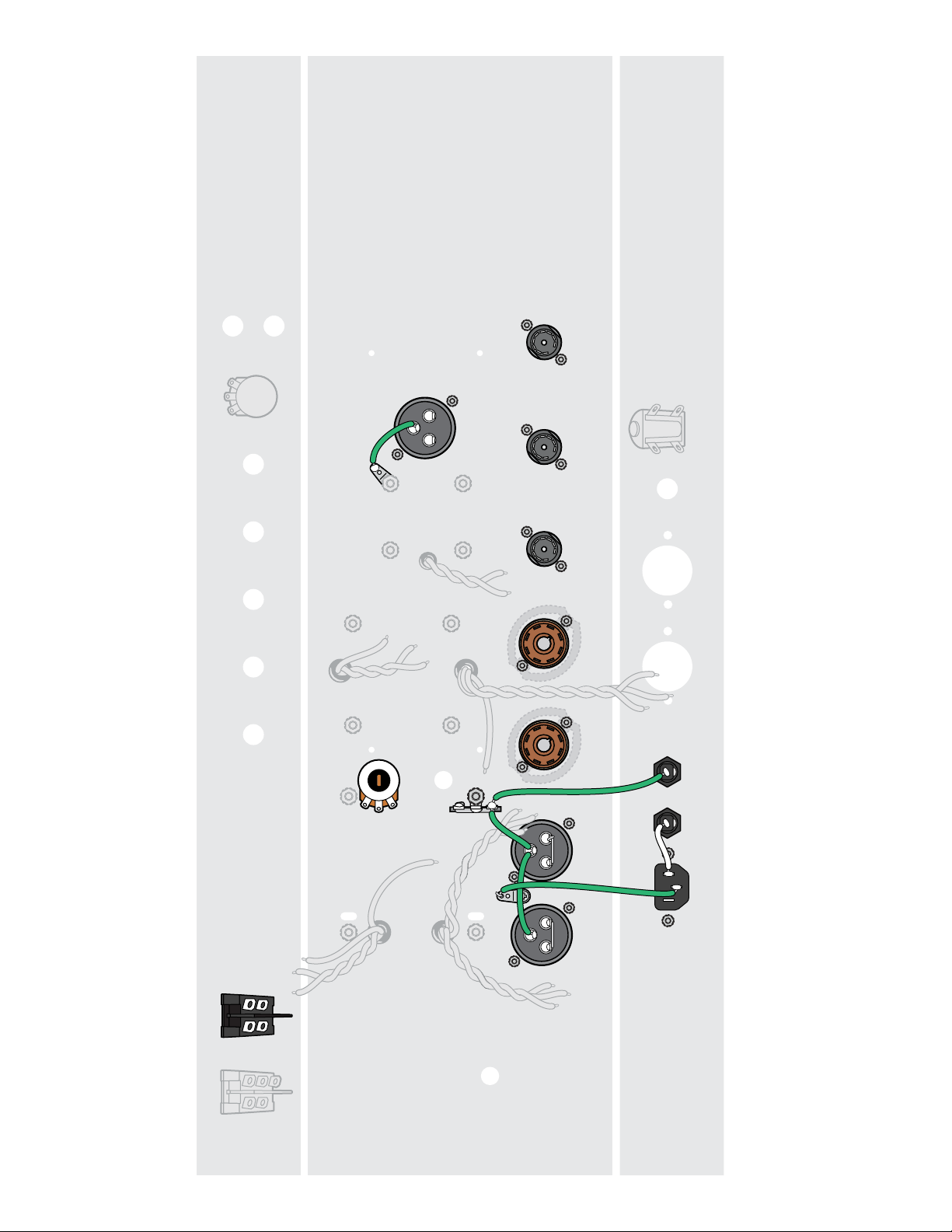
STEP 9
Ground the filter caps
Cut a 2-1/2" green jumper. Solder one
end of this jumper to the negative (-) lug
of filter cap 1. Wrap the other end of this
jumper to the negative lug of filter cap 2,
but don't solder it yet.
Cut a 1-1/2" green jumper. Solder one
end of this jumper to the negative lug of
filter cap 2 along with the jumper from
filter cap 1. Wrap the other end of the
jumper to the closest lug of the three-lug
grounding strip, but don't solder it yet.
Cut another 1-1/2" green jumper. Solder
one end to the negative (-) lug of filter cap
3. Solder the other end of the jumper to
the nearby grounding tab.
STEP 10
Connect the filter cap positive lugs
Cut two 1" green jumpers and remove
the insulation. Wrap one jumper between
filter cap 1's positive lugs and wrap the
other between filter cap 2's positive lugs.
Don't solder these jumpers yet.
STEP 11
Add one grounding tab
Use a 4-40 x 1/4" screw and locknut to
mount a grounding tab on the chassis
hole between filter cap 1 and filter cap 2.
STEP 12
Install the two large tube sockets
with spring retainers
Orient these eight-pin tube sockets so
that pin 1 is closest to the rear panel of
the chassis.
Use 4-40 x 3/8" machine screws and
locknuts to mount these sockets on the
outside of the chassis. Include a spring
retainer on the bottom of each socket
to provide support for these three tubes
when they’re installed later.
STEP 13
Install the three small tube sockets
Position these nine-pin sockets so pin 9
is closest to the rear panel of the chassis.
Use two 4-40 x 1/4" machine screws and
locknuts to mount the three remaining
tube sockets.
STEP 14
Install the H.T. fuse socket + one
jumper
Install the high-tension fuse socket in the
back panel.
Cut a 1" green jumper. Solder one end to
the back lug of the H.T. fuse socket. Solder
the other end of the jumper to the closest
lug of the three-lug grounding strip along
with the jumper already in place.
STEP 15
Install the mains input + two
jumpers
Use 4-40 x 3/8" screws and locknuts to
install the power input with its central
ground lug facing the chassis opening.
Cut one 2-1/4" green jumper. Solder one
end of this jumper to the central ground
lug of the mains input. Wrap the other
end of this jumper to the ground tab
between filter cap 1 and filter cap 2.
Cut one 3" white jumper. Solder one
end of this jumper to the right lug of the
power inlet and solder the other end of
this jumper to the back lug of the mains
fuse socket.
STEP 16
Add the standby switch
Mount the standby switch by pushing the
switch through the front of the chassis
and pulling the four black tabs out from
the switch housing so they sit tight
against the inside of the chassis.
STEP 17
Install the bias pot
Mount the 10KL bias pot in the floor of
the chassis as shown.
In building this amp, you’ll cut
pieces of wire to make connections.
These connecting wires are called
jumpers, and you’ll use a lot of them
in building this amp.
stewmac.com 14 © 2019 StewMac
V5
EL34 V4
EL34
POWER STANDBY PRESENCE BASS MIDDLE TREBLE MASTER
VOLUME
PREAMP
VOLUME
INPUT
(NORMAL)
H.T. FUSE
V3
12AX7 V2
12AX7 V1
12AX7
SPEAKER EXTENSION
SPEAKER
VOLTAGE
SELECTOR
IMPENDANCE
SELECTOR
FILTER CAP 3
FILTER CAP 2FILTER CAP 1
MAINS
FUSE
MAINS INPUT
4
3
2
1
8
7
6
5
6
4
3
2
1
9
8
7
5
6
4
3
2
1
9
8
7
5
6
4
3
2
1
9
8
7
5
B
A
-
B
A
-
B
A
-
1
2
4
3
1
M
A
2
5
0
K
L
2
5
K
L
1
M
A
5
K
L
4
3
2
1
8
7
6
5
1
2
4
3
LO
HI
STEP 00
Enlarged to
show detail
Mount jacks outside
on the front panel
1
2
4
3
1
2
4
3
LO
HI

stewmac.com 15 © 2019 StewMac
STEP 18
Install the remaining control pots
Mount the control pots so their three lugs
are facing the chassis opening. When
we refer to these lugs as left or right, it’s
assuming you’re looking at the pot from
the same point of view as the wiring
diagram.
Mount them as follows:
Presence: 5KL pot
Bass: 1MA pot
Middle (mids): 25KL pot
Treble: 250KL pot
Master Volume: 1MA
STEP 19
Wire the input jacks
Use two 4-lug jacks for the input jacks.
For these steps, we’ll refer to the names
they are given on the front panel, high-
sensitivity and low-sensitivity.
Mount the jacks temporarily on the
outside of the chassis, in their respective
holes with their lugs pointing away from
the power switch.
Mounting the jacks outside the chassis
will hold them in position and give you
room to do the tricky job of wiring them
up. Afterward, they’ll fit nicely inside the
chassis as a pre-wired assembly.
Cut a 1" piece of white wire and wrap one
end to lug 2 of the high-sensitivity jack.
Wrap the other end to lug 4 of the high-
sensitivity jack.
Run one lead of a 1M resistor through lug
1 of the high-sensitivity jack and the other
lead through lug 2 of the high-sensitivity
jack. Solder these leads in place on both
jacks, along with the jumper wrapped to
lug 1, and trim any excess leads.
Cut a 1-1/8" white jumper and wrap one
end to lug 4 of the low sensitivity jack.
Wrap the other end to lug 3 of the high-
sensitivity jack. Solder this jumper in
place on both lugs and trim any excess
leads.
Cut a 2-1/2" white jumper and wrap one
end to lug 2 of the low-sensitivity jack.
Wrap the other end to lug 4 of the high-
sensitivity jack. Solder this jumper in
place on lug 2 of the low-sensitivity jack
and trim any excess lead.
Cut a 2-1/2" green jumper and solder one
end to lug 4 of the high-sensitivity jack
along with the two jumpers already in
place. Trim any excess leads.
Remove these wired-up input jacks and
mount them in the same holes on the
inside of the chassis. (Their lugs are now
facing the power switch.)
STEP 20
Ground all control pots
Turn all pot shafts counterclockwise to
their zero position before starting this
step. This is because you’ll be applying
heat to their cases, and if the heat lingers
too long it could create an impression on
the wiper inside. This isn’t a concern if the
pot is in the zero position.
Straighten out the bare copper wire and
run it from the preamp volume pot to
the presence pot. Starting at the preamp
control pot, solder the bare copper wire
to the back of each pot. If you are having
trouble applying enough heat to the
back of the pot to get the solder to take,
create a solder puddle on the back of the
pot before attempting to solder the bare
copper wire to the housing.
Once you have the bare wire soldered
to the back of each pot, trim away any
excess wire.

stewmac.com 16 © 2019 StewMac
V5
EL34 V4
EL34
POWER STANDBY PRESENCE BASS MIDDLE TREBLE MASTER
VOLUME
PREAMP
VOLUME
INPUT
(NORMAL)
H.T. FUSE
V3
12AX7 V2
12AX7 V1
12AX7
SPEAKER EXTENSION
SPEAKER
VOLTAGE
SELECTOR
IMPENDANCE
SELECTOR
FILTER CAP 3
FILTER CAP 2FILTER CAP 1
MAINS
FUSE
MAINS INPUT
4
3
2
1
8
7
6
5
6
4
3
2
1
9
8
7
5
6
4
3
2
1
9
8
7
5
6
4
3
2
1
9
8
7
5
B
A
-
B
A
-
B
A
-
1
2
4
3
1
2
4
3
1
M
A
2
5
0
K
L
2
5
K
L
1
M
A
5
K
L
4
3
2
1
8
7
6
5
LO
HI
.1μF

stewmac.com 17 © 2019 StewMac
STEP 21
Ground three control pots
Cut three 1" jumpers of green wire, pull
off their insulation, and bend one end of
each into a hook.
Starting with the preamp volume pot,
solder the hook end of the jumper to the
left lug of the pot. Solder the straight end
of this jumper to the back of the pot.
Repeat this process for the master volume
pot and the mids pot.
STEP 22
Add one white jumper
Cut a 3" white jumper. Solder one end of
this jumper to the middle lug of the treble
pot. Solder the other end of this jumper
to the right lug of the master volume pot.
STEP 23
Add two white jumpers
Cut a 3-1/2" white jumper. Solder one
end to the left lug of the bass pot and
solder the other end to the right lug of
the mids pot.
Cut one 4-1/4" white jumper. Solder one
end to the middle lug of the bass pot.
Wrap the other end to the left lug of the
treble pot, but don't solder it yet. You'll
be adding a jumper from the turret board
here later.
STEP 24
Add a 4.7k resistor
Run one lead of a 4.7k resistor down
through the left lug of the presence
pot. Solder this lead to the back of the
presence pot and then to the left lug of
the presence pot. Wrap the other lead
of this resistor to the right lug of the
presence pot but don't solder it yet.
STEP 25
Add a .1μF capacitor
Solder one lead of a .1μF cap to the
middle lug of the presence pot. Solder
the other lead of this capacitor to the
back of the presence pot. Trim away all
excess leads from the components on
the presence pot.
STEP 26
Power transformer brown and blue
leads + one jumper
Run the brown power transformer lead
to the ground tab between filter cap 1
and filter cap 2. Trim this lead to length
and solder it to the tab along with the
green jumper from the middle lug of the
power inlet.
Run the blue power transformer lead to
the power switch and wrap it to the top
left lug.
Cut one 1-1/2" white jumper and solder
one end to the bottom right lug of the
power switch. Solder the other end of this
jumper to the top left lug of the power
switch along with the blue transformer
lead already in place.
STEP 27
Power transformer red leads
Run the two red wires from the power
transformer standby switch. Trim these
wires to length, solder one to the bottom
left lug of the standby switch, and solder
the other to the right bottom lug of the
standby switch. Either wire can go to
either lug.

stewmac.com 18 © 2019 StewMac
V5
EL34 V4
EL34
POWER STANDBY PRESENCE BASS MIDDLE TREBLE MASTER
VOLUME
PREAMP
VOLUME
INPUT
(NORMAL)
H.T. FUSE
V3
12AX7 V2
12AX7 V1
12AX7
SPEAKER EXTENSION
SPEAKER
VOLTAGE
SELECTOR
IMPENDANCE
SELECTOR
FILTER CAP 3
FILTER CAP 2FILTER CAP 1
MAINS INPUT MAINS
FUSE
6
4
3
2
1
9
8
7
5
6
4
3
2
1
9
8
7
5
6
4
3
2
1
9
8
7
5
B
A
-
B
A
-
B
A
-
1
2
4
3
1
2
4
3
LO
HI
4
3
2
1
8
7
6
5
4
3
2
1
8
7
6
5
Table of contents
Other StewMac Amplifier manuals


