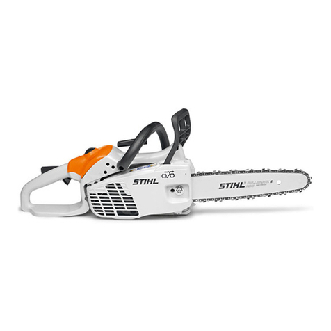
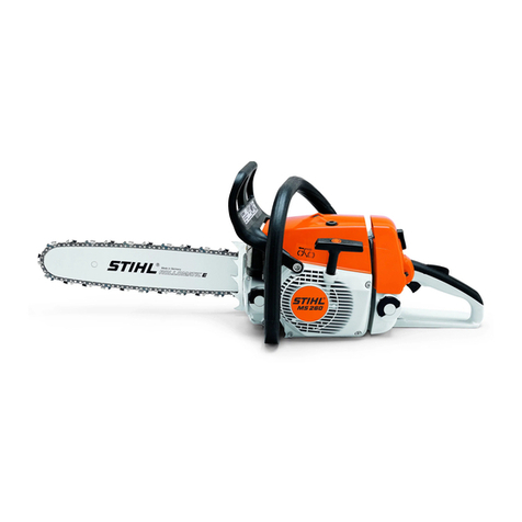
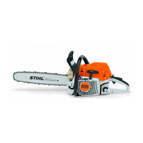
Stihl MS 270 User manual

Online version - not for reprint
1MS 270, MS 280
q
© 2002 Andreas Stihl AG & Co., Waiblingen
Contents
1 Introduction 3
2 Safety Precautions 4
3 Specifications 5
3.1 Engine 5
3.2 Fuel System 5
3.3 Ignition System 5
3.4 Chain Lubrication 5
3.5 Tightening Torques 6
4 Troubleshooting
Chart 8
4.1 Clutch, Chain Drive,
Chain Brake, Chain
Tensioner 8
4.2 Rewind Starter 10
4.3 Chain Lubrication 11
4.4 Ignition System 12
4.5 Carburetor 13
4.6 Engine 16
5 Clutch, Chain Drive,
Chain Brake and
Chain Tensioner 17
5.1 Clutch Drum/Chain
Sprocket 17
5.2 Replacing the Chain
Catcher 18
5.3 Clutch 18
5.4 Chain Brake 20
5.4.1 Checking Operation 20
5.4.2 Removing 21
5.4.3 Installing 23
5.5 Chain Brake with
QuickStop Super 25
5.5.1 Removing 25
5.5.2 Installing 26
5.5.3 Checking Play 28
5.5.4 Adjusting Play 29
5.5.5 Brake Cable 29
5.5.6 Checking Operation
of Coasting Brake 30
5.6 Brake Spring Anchor
Pin 30
5.7 Chain Tensioner 31
5.8 Bar Mounting Studs 32
6 Engine 33
6.1 Muffler/Spark
Arresting Screen 33
6.2 Leakage Test 33
6.2.1 Preparations 33
6.2.2 Pressure Test 34
6.2.3 Vacuum Test 35
6.3 Oil Seals 36
6.4 Shroud 37
6.5 Cylinder and Piston 38
6.5.1 Removing 38
6.5.2 Installing 39
6.6 Piston Rings 42
6.7 Crankcase 43
6.7.1 Crankshaft 43
6.8 Decompression Valve 44
7 Ignition System 44
7.1 Ignition Module 45
7.1.1 Ignition Timing 45
7.1.2 Removing and
Installing 45
7.1.3 Testing the Ignition
Coil 46
7.2 Spark Plug Boot 48
7.3 Flywheel 48
7.4 Short Circuit Wire/
Ground Wire 49
7.5 Stop Contact 50
7.6 Ignition System
Troubleshooting 51
8 Rewind Starter 54
8.1 General 54
8.2 Fan Cover 54
8.3 Pawls 54
8.4 Rope Rotor 55
8.5 Starter Rope 56
8.5.1 ElastoStart 57
8.5.2 Tensioning 57
8.6 Starter Rope Guide
Bush 58
8.7 Replacing the Rewind
Spring 59
9 AV Handle System 60
9.1 Handlebar 60
9.2 Replacing Annular
Buffers 61
9.2.1 Crankcase 61
9.2.2 Tank Housing 62
9.3 Spring 63
10 Master Control/
Handle System 64
10.1 Switch Shaft 64
10.2 Throttle Trigger/
Interlock Lever 65
10.2.1 Machines without
QuickStop Super 65
10.2.2 Machines with
QuickStop Super 66
11 Chain Lubrication 67
11.1 Pickup Body/
Suction Hose 67
11.2 Delivery Hose 68
11.3 Valve 69
11.4 Oil Pump 70
11.5 Fan Housing 70
12 Fuel System 71
12.1 Air Filter 71
12.2 Carburetor 72
12.2.1 Removing and
Installing 72
12.2.2 Leakage Test 73
12.3 Servicing the
Carburetor 73
12.3.1 Metering Diaphragm 73
12.3.2 Inlet Needle 74
12.3.3 Fixed Jet 75
12.3.4 Pump Diaphragm 76
12.3.5 Accelerator Pump 77
12.4 Adjusting 79
12.4.1 Standard Setting 80
12.5 Tank Vent 81
12.6 Pickup Body 82
12.7 Fuel Hose 82

Online version - not for reprint
3MS 270, MS 280
1 Introduction
This service manual contains
detailed descriptions of all the
typical repair and servicing
procedures for this power tool.
You should make use of the
illustrated parts lists while carrying
out repair work. They show the
installed positions of the individual
components and assemblies.
Refer to the latest edition of the
relevant parts list to check the part
numbers of any replacement parts.
A fault on the machine may have
several causes. To help locate the
fault, consult the troubleshooting
charts for all assemblies and
systems in this manual and the
"STIHL Service Training System".
Refer to the "Technical Information"
bulletins for engineering changes
which have been introduced since
publication of this service manual.
Technical information bulletins also
supplement the parts list until an
updated edition is issued.
The special tools mentioned in the
descriptions are listed in chapter
"Special Servicing Tools" of this
manual. Use the part numbers to
identify the tools in the "STIHL
Special Tools" manual.
The manual lists all special
servicing tools currently available
from STIHL.
Symbols are included in the text and
pictures for greater clarity.
The meanings are as follows:
In the descriptions:
= Action to be taken as
shown in the illustration
(above the text)
– = Action to be taken that is
not shown in the illustration
(above the text)
In the illustrations:
Pointer
Direction of movement
Service manuals and all technical
Information bulletins are intended
exclusively for the use of STIHL
servicing dealers. They must not be
passed to third parties.
Servicing and repairs are made
considerably easier if the clamp (1)
5910 890 2000 is used to mount the
machine on assembly stand (2)
5910 890 3100 so that one clamp
screw engages the outer 10 mm
bore (3) in the assembly stand.
The chainsaw can then be swivelled
to the best position for the ongoing
repair.
To service the underside of the
machine, turn it upside down and
mount it in the assembly stand.
Pull the hand guard back against
the front handle for this purpose.
Always use original STIHL
replacement parts.
They can be identified by the
STIHL part number,
the STIH)
STIH)STIH)
STIH) logo
and the STIHL parts symbol (
This symbol may appear alone on
small parts.

Online version - not for reprint
4MS 270, MS 280
If the engine is started up in the
course of repairs or maintenance
work, observe all local and country-
specific safety regulations as well
as the safety precautions and
warnings in the owner’s manual.
Gasoline is an extremely flammable
fuel and can be explosive in certain
conditions.
Improper handling may result in
burns or other serious injuries.
Warning!
Do not smoke or bring any fire,
flame or other source of heat near
the fuel. All work with fuel must be
performed outdoors only. Spilled
fuel must be wiped away
immediately.
2 Safety Precautions

Online version - not for reprint
5MS 270, MS 280
3 Specifications
3.1 Engine
MS 270 MS 280
Displacement: 49.6 cm3 54.2 cm3
Bore: 44.0 mm 46.0 mm
Stroke: 32.6 mm 32.6 mm
Engine power to ISO 7293: 2.6 kW (3.54 HP)
at 9,500 rpm
2.8 kW (3.81 HP)
at 9,500 rpm
Max. permissible engine
speed (with bar and chain): 13,500 ± 150 rpm 13,500 ± 150 rpm
Idle speed: 2,800 rpm 2,800 rpm
Clutch: Three-shoe centrifugal
clutch without linings
Three-shoe centrifugal
clutch without linings
Clutch engages at: 3,300 rpm 3,300 rpm
Crankcase leakage test
– at gauge pressure:
– under vacuum:
60 kPa (0.6 bar)
40 kPa (0.4 bar)
60 kPa (0.6 bar)
40 kPa (0.4 bar)
3.2 Fuel System
Carburetor leakage test
at gauge pressure: 80 kPa (0.8 bar) 80 kPa (0.8 bar)
Tank vent operates
at gauge pressure: 30 kPa (0.3 bar) 30 kPa (0.3 bar)
Fuel: see owner’s manual see owner’s manual
3.3 Ignition System
Air gap between ignition
module and fanwheel: 0.20 – 0.30 mm 0.20 – 0.30 mm
Spark plug (resistor type): NGK BPMR 7A NGK BPMR 7A
Electrode gap: 0.5 mm 0.5 mm
3.4 Chain Lubrication
Fully automatic speed-controlled oil pump with rotary piston
Oil delivery rate: 10 cc/min at 10,000 rpm 10 cc/min at 10,000 rpm

Online version - not for reprint
6MS 270, MS 280
3.5 Tightening Torques
DG and P screws (Plastoform) are used in polymer and light-alloy components. These screws form a
permanent thread when they are installed for the first time. They can be removed and installed as often as
necessary without detrimentally affecting the strength of the screwed assembly, providing the specified
tightening torque is observed.
For this reason always use a torque wrench.
Fastener Thread For component Torque Remarks
size Nm
Spline screw IS-M4x8 Cover plate, chain tensioner/crankcase 3.0 1)
Countersunk screw IS-PT4x12 Cover plate/chain sprocket cover 2.5 2)
Spline screw IS-B3.9x13 Cover plate/fan cover 1.5
Spline screw IS-M8x22 Brake band/crankcase 10.0 3)
Spline screw IS-P4x10 Brake cable, support/tank housing 1.0 4)
Collar screw IS-M10/M8 Guide bar/crankcase 30.0 2) 5) 6)
Collar screw IS-M8x21.5 Guide bar/crankcase 23.0 7) 3) 8)
Spline screw IS-DG4x16 Cover/crankcase 3.0
Decompression
valve IS-M10x1 Decompression valvel 14.0
Collar nut M5 Filter base/baffle/carburetor 5.0
Spline screw IS-B4.2x9.5 Screen/muffler 2.0 9)
Spline screw IS-DG5x24 Hand guard, sleeve/fan cover 4.0
Spline screw IS-DG5x24 Shroud/crankcase 4.5
Spline screw IS-DG5x24 Shroud/fan housing 4.5
Spline screw IS-DG5x18 Chain catcher/crankcase 9.0
Spline screw IS-DG5x18 Spiked bumper/crankcase 9.0
Spline screw IS-DG5x24 Fan cover/fan housing 4.0
Remarks:
1) Special accessory
2) Only machines with quick chain adjuster
3) Secure screw with Loctite 243
4) Only machines with QuickStop Super
5) Secure screw with Loctite 270
6) With quick chain adjuster
7) Only machines without quick chain adjuster
8) Without quick chain adjuster
9) Only muffler with spark arresting screen

Online version - not for reprint
7MS 270, MS 280
Fastener Thread For component Torque Remarks
size Nm
Spline screw IS-DG5x24 Fan housing/crankcase 9.0
Spline screw IS-DG5x24 Fan housing/bearing plug 4.0
Clutch carrier M12x1L Carrier/crankshaft 50.0
Spline screw IS-DG5x18 Muffler/cylinder 9.0
Nut M8x1 Flywheel/crankshaft 28.0
Pan head screw M4x8 Inner side plate 3.0 1)
Collar screw M8SK6 Dihedral sleeve/crankcase/bar guide 30.0 1) 6)
Spline screw IS-M5x28 Cylinder/crankcase 9.0
Spark plug M14x1.25 Spark plug 25.0
Spline screw IS-DG4x20 Ignition module/cylinder 4.0
Spline screw IS-DG4x16 Oil pump/crankcase 3.0
Remarks:
1) Only machines with quick chain adjuster
6) Secure screw with Loctite 270
Screws secured with adhesive are easier to loosen if the adhesive is heated first with a hot air blower.
Exercise caution on polymer components.
Use the following procedure to fit a P (Plastoform) screw in an existing thread:
– Place the P screw in the hole and rotate it counterclockwise until drops down slightly.
– Tighten the screw clockwise to the specified torque.
This procedure ensures that the screw engages properly in the existing thread and does not form a new thread,
which would weaken the assembly.
Power screwdriver speed setting for polymer:
– P screws: max. 500 rpm

Online version - not for reprint
8MS 270, MS 280
4 Troubleshooting Chart
4.1 Clutch, Chain Drive, Chain Brake, Chain Tensioner
Condition Cause Remedy
Saw chain stops under load at full
throttle
Clutch shoes badly worn Replace clutch shoes or install new
clutch
Clutch drum badly worn Install new clutch drum
Brake band stuck Check freedom of movement
and function of brake band. If
necessary, adjust brake cable of
QuickStop Super (option)
QuickStop Super brake cable
broken (option)
Replace the brake cable
Saw chain rotates at idle speed Engine idle speed too high Readjust with idle speed screw
(counterclockwise)
Clutch springs stretched or fatigued Replace the clutch springs
Clutch spring hooks broken Replace the clutch springs
Loud noises Clutch springs stretched or fatigued Replace all clutch springs
Needle cage damaged Fit new needle cage
Clutch shoe retainer broken Fit new retainer
Clutch shoes and carrier worn Install new clutch
Chain sprocket wears rapidly Chain not properly tensioned Tension chain as specified
Wrong chain pitch Fit chain of correct pitch

Online version - not for reprint
9MS 270, MS 280
Condition Cause Remedy
Saw chain does not stop
immediately when brake is
activated
Brake spring stretched or broken Fit new brake spring
Brake band stretched/worn/broken Fit new brake band

Online version - not for reprint
10 MS 270, MS 280
4.2 Rewind Starter
Condition Cause Remedy
Starter rope broken Rope pulled out too vigorously as
far as stop or over edge, i.e. not
vertically
Fit new starter rope
Normal wear Fit new starter rope
Rewind spring broken
(rope does not rewind)
Spring overtensioned – no reserve
when rope is fully extended
Fit new rewind spring
Very dirty or corroded Clean or replace rewind spring
Starter rope can be pulled out
almost without resistance
(crankshaft does not turn)
Guide peg on pawls or pawls
themselves are worn
Fit new pawls
Spring clip fatigued Fit new spring clip
Starter rope is difficult to pull
and rewinds very slowly
Starter mechanism is very dirty Thoroughly clean complete starter
mechanism
Lubricating oil on rewind spring
becomes viscous at very low
outside temperatures (spring
windings stick together)
Apply a few drops of kerosine
(paraffin) to spring, then pull rope
carefully several times until normal
action is restored

Online version - not for reprint
11MS 270, MS 280
4.3 Chain Lubrication
In the event of trouble with the chain
lubrication system, check and
rectify other sources of faults before
disassembling the oil pump.
Condition Cause Remedy
Chain receives no oil Oil tank empty Fill up with oil
Oil inlet hole in guide bar is
blocked
Clean oil inlet hole
Intake hose or pickup body
(strainer) clogged or intake hose
ruptured
Wash intake hose and pickup body
(strainer) in fresh STIHL cleaner or
replace if necessary
Valve in oil tank blocked Clean or replace valve
Teeth on pump piston and/or worm
worn
Install new oil pump and/or new
worm
Oil pump hoses blocked/damaged Clean or replace hoses
Machine losing chain oil Oil pump hoses porous/ruptured Fit new hoses
Bore in pump housing worn Fit new oil pump
Oil pump delivers insufficient oil Pump piston worn Fit new oil pump
Oil pump hoses not installed
correctly/leaking/ruptured/blocked
Check correct installation of hoses
or clean/replace hoses
Bore in pump housing worn Fit new oil pump

Online version - not for reprint
12 MS 270, MS 280
4.4 Ignition System
Exercise extreme caution while
carrying out maintenance and
repair work on the ignition system.
The high voltages which occur can
cause serious or fatal accidents!
Condition Cause Remedy
Engine runs roughly, misfires,
temporary loss of power
Spark plug boot is loose Press boot firmly onto spark plug
and fit new spring if necessary
Spark plug sooted, smeared
with oil
Clean the spark plug or replace if
necessary
Weak spark or no spark Faulty insulation on ignition lead or
short circuit wire. Use ohmmeter to
check ignition lead for break. If
break is detected or high resistance
measured, fit a new ignition lead
Incorrect air gap between ignition
coil and flywheel
Set air gap correctly
Flywheel cracked or has other
damage
Install new flywheel
Check operation of spark plug.
Inspect Master Control lever,
ignition coil/lead for damage
insulation and leakage current
Clean or replace spark plug,
replace faulty parts of ignition
system
No ignition spark Check operation of Master Control
lever and ignition module

Online version - not for reprint
13MS 270, MS 280
4.5 Carburetor
Condition Cause Remedy
Carburetor floods;
engine stalls
Inlet needle not sealing. Foreign
matter in valve seat or cone
damaged
Remove and clean or replace the
inlet needle, clean the fuel tank,
pickup body and fuel line if
necessary
Inlet control lever sticking on
spindle
Free off inlet control lever
Helical spring not located on nipple
of inlet control lever
Remove the inlet control lever and
refit it correctly
Perforated disc on diaphragm is
deformed and presses constantly
against the inlet control lever
Fit a new metering diaphragm
Inlet control lever too high
(relative to correct installed
position)
Set inlet control lever flush with top
edge of housing
Poor acceleration Idle jet too lean Rotate low speed screw (L)
counterclockwise (richer), no
further than stop
Main jet too lean Rotate high speed screw (H)
counterclockwise (richer), no
further than stop
Inlet control lever too low
(relative to correct installed
position)
Set inlet control lever flush with top
edge of housing
Inlet needle sticking to valve seat Remove inlet needle, clean and
refit
Diaphragm gasket leaking Fit a new diaphragm gasket
Metering diaphragm damaged or
shrunk
Fit a new metering diaphragm

Online version - not for reprint
14 MS 270, MS 280
Condition Cause Remedy
Engine speed drops quickly under
load – low power
Air filter dirty Clean the air filter
Tank vent faulty Replace tank vent
Leak in fuel line between tank
and fuel pump
Seal connections or install a new
fuel line
Pump diaphragm damaged or
fatigued
Fit a new pump diaphragm
Main jet bores or ports blocked Clean the bores and ports
Fuel pickup body dirty Clean the pickup body, fit a new
filter
Fuel strainers dirty Clean the fuel strainers
Spark arresting screen dirty Clean or replace spark arresting
screen
Setting of high speed screw (H)
too rich
Reset high speed screw (H)
correctly
Throttle shutter not opened fully Check linkage
Engine will not idle,
idle speed too high
Throttle shutter opened too wide
by idle speed screw (LA)
Reset idle speed screw (LA)
correctly
Engine leaking Seal the engine

Online version - not for reprint
15MS 270, MS 280
Condition Cause Remedy
Engine stalls at idle speed Idle jet bores or ports blocked Clean jet bores and ports and blow
clear with compressed air
Idle jet too rich or too lean Set low speed screw (L) correctly
Setting of idle speed (LA)
incorrect – throttle shutter
completely closed
Set idle speed screw (LA) correctly
Small plastic plate in valve jet
does not close
Clean or renew valve jet

Online version - not for reprint
16 MS 270, MS 280
4.6 Engine
Always check and, if necessary,
repair the following parts before
looking for faults on the engine:
– Air filter
– Fuel system
– Carburetor
– Ignition system
Condition Cause Remedy
Engine does not start easily, stalls
at idle speed, but operates normally
at full throttle
Oil seals in crankcase damaged Replace the oil seals
Crankcase leaking or damaged
(cracks)
Seat or replace the crankcase
Muffler leaking Replace the muffler
Engine does not deliver full power
or runs erratically
Piston rings worn or broken Fit new piston rings
Muffler/spark arresting screen
carbonized
Clean the muffler (inlet and
exhaust), replace spark arresting
screen
Air filter element dirty Replace air filter element
Fuel/impulse line severely kinked or
damaged
Replace lines or position them free
from kinks
Decompression valve sticking Replace the decompression valve
Engine overheating Insufficient cylinder cooling. Air
inlets in fan housing blocked or
cooling fins on cylinder very dirty
Thoroughly clean all cooling air
openings and the cylinder fins

Online version - not for reprint
17MS 270, MS 280
– Remove the chain sprocket
cover.
– Remove the bar an chain – wear
work gloves to protect your hands
from injury.
Disengage the chain brake by
VA
143RA004
pulling the hand guard towards
the front handle.
Remove the E-clip (1),
washer (2) and, if fitted, the rim
sprocket (3).
VA
146RA188
3
21
Pull off the clutch drum (1) with
needle cage (2).
– Inspect the needle cage for
damage.
On machines with
QuickStop Super:
VA
148RA062
1
2
– Press down the throttle trigger
interlock to disengage the
coasting brake and then pull off
the clutch drum (1) with needle
cage (2).
Pull off the chain sprocket (1) or
clutch drum (2).
– Remove the needle cage.
VA
138RA003
1
2
Inspect the clutch drum (1) for
signs of wear.
If there are noticeable wear marks
on the inside diameter of the clutch
drum (1), check its wall thickness. If
it is less than 80% of the original
wall thickness, fit a new clutch
VA
148RA101
80%
100%
1
!
drum.
If the clutch drum has to be
replaced, also check the brake band
– see 5.4.2.
5 Clutch, Chain Drive, Chain Brake and Chain Tensioner
5.1 Clutch Drum/Chain Sprocket

Online version - not for reprint
18 MS 270, MS 280
If the clutch drum is still serviceable,
use No. 120 emery paper or emery
cloth (grain size approx. 120 µm) to
clean and roughen its friction
surface.
Reassemble in the reverse
sequence.
Clean stub of crankshaft. Wash
needle cage in clean white spirit and
lubricate with STIHL multipurpose
grease – see 14.
– Rotate clutch drum/chain
sprocket and apply slight
pressure at the same time until
the oil pump drive spring
engages the notch (see arrow).
– Remove the chain sprocket
cover.
– Remove the bar and chain – wear
work gloves to protect your hands
from injury.
Take out the slotted screw (1).
VA
146RA001
1
4
2
3
Remove the side plate (2).
Take out the screw (3).
Remove the chain catcher (4).
Install in the reverse sequence.
Troubleshooting chart – see 4.1.
– Remove the clutch drum or chain
sprocket – see 5.1.
Release the twist lock (1) and lift
away the carburetor box
cover (2).
VA
146RA002
2
1
Remove the spark plug boot (1).
– Unscrew the spark plug.
VA
146RA003
1
5.2 Replacing the Chain
Catcher
5.3 Clutch

Online version - not for reprint
19MS 270, MS 280
– Close the decompression valve,
if fitted.
Push the locking strip (1)
0000 893 5903 into the spark
plug hole so that "OBEN-TOP"
faces up.
VA
146RA004
1
Unscrew the clutch from the
crankshaft clockwise (left-hand
thread).
VA
148RA068
Take the cover washer (1) off the
crankshaft stub.
VA
146RA209
1
TOP
Disassembling the clutch
Use hook (2) 5910 890 2800 to
remove the clutch springs (1).
VA
146RA205
1 2
– Pull the clutch shoes off the
carrier.
Pull the retainers off the clutch
shoes.
VA
208RA031
– Clean all parts with STIHL
cleaner – see 14.
– Replace any damaged parts.
VA
208RA026
Assembling the clutch
Slip the retainers onto the clutch
shoes.
VA
208RA029
Fit the clutch shoes (2) over the
arms (1) of the clutch carrier (3).
VA
146RA208
2 1 3

Online version - not for reprint
20 MS 270, MS 280
Clamp the clutch in a vise.
Use protective jaws so as not to
damage the clutch.
VA
146RA206
Attach one end of each spring (1)
to the clutch shoes.
Use the hook (2) 5910 890 2800
to attach other ends of springs
and press them firmly into the
clutch shoes.
VA
146RA207
2
1
Push cover washer (1), "TOP"
(arrow) facing outward, onto the
crankshaft.
VA
146RA204
1
TOP
Screw on the clutch and tighten it
down – see 3.5.
– Remove locking strip from the
cylinder.
– Screw home spark plug and
tighten it down – see 3.5.
VA
135RA024
– Fit boot on the spark plug.
– Fit the shroud.
– Install clutch drum/chain sprocket
– see 5.1.
The chain brake is one of the most
important safety devices on the
chainsaw. Its efficiency is measured
in terms of the chain braking time,
i.e. the time that elapses between
activating the brake and the saw
chain coming to a complete
standstill. The shorter the braking
time, the better the efficiency and
protection offered against being
injured by the rotating chain.
Contamination (with chain oil, chips,
fine particles of abrasion, etc.) and
smoothing of the friction surfaces of
the brake band and clutch drum
impair the coefficient of friction.
This, in turn, reduces the frictional
forces and thus prolongs the
braking time. A fatigued or stretched
brake spring has the same negative
effect.
– Start the engine.
– With the chain brake activated
(locked), open the throttle wide
for a brief period (max.
3 seconds) – the chain must not
rotate.
– With the chain brake released,
open the throttle wide and
activate the brake manually – the
chain must come to an abrupt
stop.
The braking time is in order if
deceleration of the saw chain is
imperceptible to the eye.
5.4 Chain Brake
5.4.1 Checking Operation
This manual suits for next models
1
Table of contents
Other Stihl Chainsaw manuals

Stihl
Stihl 056 Quick start guide

Stihl
Stihl MSA 60.0 C User manual

Stihl
Stihl MS 210 User manual

Stihl
Stihl MS 261 C User manual

Stihl
Stihl MS 201 C-M User manual

Stihl
Stihl MSA 160 T User manual

Stihl
Stihl MS 201 TC-M User manual

Stihl
Stihl HSE 42 User manual

Stihl
Stihl MS 231 User manual

Stihl
Stihl 9 User manual

Stihl
Stihl MS 362 C-M User manual

Stihl
Stihl MS 201 C-M User manual

Stihl
Stihl MS 193 User manual

Stihl
Stihl MS 461 Rescue User manual

Stihl
Stihl MS 200 User manual

Stihl
Stihl MSE 140 User manual

Stihl
Stihl MS 201 TC-M User manual

Stihl
Stihl MS 880 User manual

Stihl
Stihl MS 193 T User manual

Stihl
Stihl 018503 User guide