Stinson SR 9 User manual

MONOCULP/SR 9
MANUAL
BR COLOR BY COLOR
BW COLOR RW COLOR


Caution!
You should not regard this plane as a toy!
To ensure safety, please read this instruction manual thoroughly
before assembly.
Building and operating a model plane requires diligent practice and
correct guidance. An inexperienced flyer can cause serious injury
and property damage.
Seek the assistance of an experienced RC pilot or model airplane
club for help with assembly, operation and maintenance to ensure
your flying experience is both enjoyable and safe.
Fly only in AMA (Academy of Model Aeronautics) approved areas.
Approved areas or areas approved by the Model Association of
your country.

Main Landing Gear Installation and Tail wheel Set
Drill a hole and make it fit the steering tube. (Do not glue it into
position untill the tail wheel installation step is completed.)
Assembly photo for the tail wheel parts.
Use the tail wheel bracket as a template and drill holes for the
mounting bolts.
Install the blind nuts through the openning in the rear of the
fuselage.
Attach the tail wheel bracket and secure the bolts with Blue
Loctite.
Insert the steering arm into the rudder steering tube and position
the tube ready for gluing. Tighten the set nuts.
Epoxy the steering tube in place as shown.

Main Landing Gear Installation
Install the landing gear in the pre-drilled holes with the supplied
bolts and locking nuts. Secure the bolts with Blue Loctite.
Insert the landing gear into the covers before you install the
landing gear axles.
Install the landing gear axles with lock nuts but do not tighten yet.
Install the wheel and tighten the collar set screw using a drop of
Blue Loctite. Make sure the wheel rotates freely.
Slipping the wheel pant over the axles and mark the position for
the two attached bolts.
Drill the holes for the attached bolts and install the blind nuts as
shown.
Mount the wheel pants andsecure the bolts with a drop ofBlue
Loctite.

Doors and Stairs
Find out below parts for this step.
Findout the holes inside of the fuselage for the locks of the door.
Stick the locks onto the door in the right position.
Find out the holes inside of the fuselage for the hinges of the door.
Fix it up with self-taps as shown.
Install the stairs into the fuselage with screws as shown.
Repeat it the same on the other side of the fuselage.

Rudder Installation
Drill holes for the mounting screws. Fit the servos as shown with
the servo label facing the rudder. Harden the area around the
holes with a drop of thin CA
Use brass crimps on eachcable and thread, the cablethrough the
end of thepull-pull connector.
Crimp the brass tube with acrimping tool or pliers
A drop of thin CA may be applied to the brass tube to help secure
the cable
Install the rudder ball linkswith bolts and locking nuts.
Check the pull-pull cables. Rudder and the rudder servo should
both be in the neutral position.

Stabilizer Installation
Use the safety clips (buyseparately) to secure theservo and servo
extension.
Install servos as shown with the servo label facing the rear of the
fuselage.
Install the stab with mounting bolts and washers. Assemble the
servo arm in the vertical position as shown. Adjust the pushrod
length so that the servo and elevator are both in the neutral
position.
Repeat the previous steps for the other wing. Install the stabilizer
tube and bolts.

Engine Installation
Use a drill to drill screw holes for engine Installation.
The holes position for 3W & DL have been laser scribed on the
firewall.
Insert the bolts through flat fender washers, the firewall and into
the engine stand offs. Tighten firmly. Secure mounting bolt nuts
with Blue Loctite.
Use a bit to drill a pushrod exit hole on the firewall in line with the
engine carburetor throttle arm.
Attach the ball link to the throttle pushrod and secure to the
carburetor throttle arm with a bolt and nylon lock nut.
Insert the throttle servo into the servo mounting tray with an
output arm forward. Insert the throttle pushrod into the servo
arm easy link.
Mark a line for the throttle servo tray, then glue it to the fuselage.
Use a drill to drill the servo mounting holes. Install the servo with
servo screws.
Insert the throttle pushrod into the servo easy link. Move the
servo arm to the center position. So that carburetor is half open.
Tighten the easy link set screw.

Fuel Tank
Install the inside parts of fueltank as shown.
Assemble the outside fuelpipe as shown.
Tighten the velcro ties secure the fuel tank.
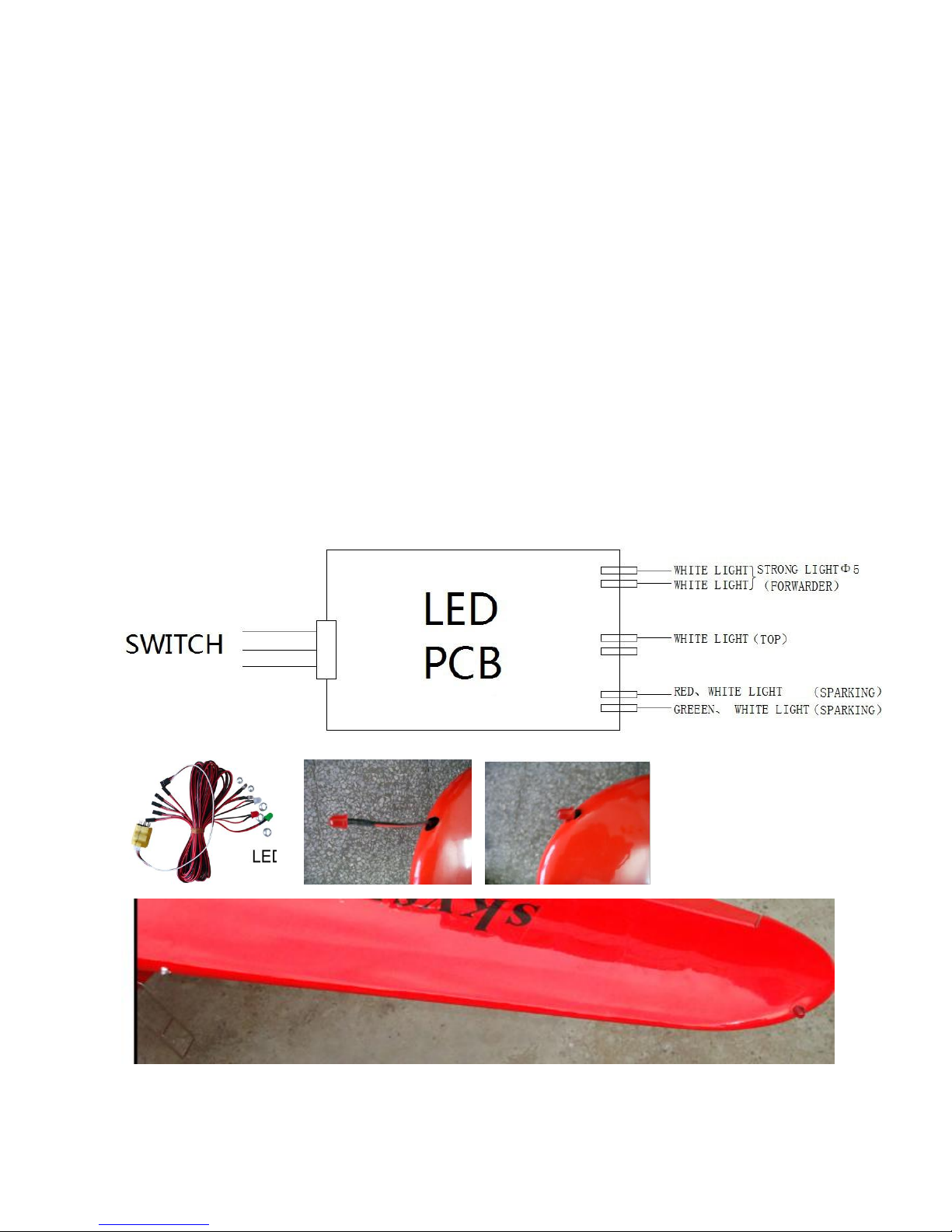
LED light
Find out the LED light system.
Insert the LED light into the tubes as shown.
Find out the holes for the LED light in the wings, both the wing tips
and the middle of the wings.
The voltage for the light is 6V.
Insert the LED light wire into the tubes for the wire specially.

Main Wing Assembly
Remove the covering from the servo position as shown.
Remove the covering from the servo position as shown.
Put the servo into the servo hole, and mark the position for the
screws to secure the servo in place. Pull the extension lead
through to the root of the wing.
Drill holes for the servomounting screws and harden the wood
aroundthe holes with a drop ofthin CA.
Install servo arm facing toward the wing tip and adjust pushrod
length to ensure the aileron and servo are in the neutral position.
Repeat the previous steps for the other wing.
Please install the wing tube and wing bolts in the final assembly.
Connect the two wings with carbon fiber tube and four nylon
screw supplied.

Wing Support
Find out 4 pcs wing support cover and 2 pcs of wing support.
Insert the wing support into the support cover.
Screw the wing support onto the wing and the fuselage.
Stick or screw the wing support cover with glue or screws.
Install the props and the scale spinner.

Float Installation
(Buy separately. If you want this part, please contact with your local distributor.)

Center of Gravity
The center of gravity is on the rear of the wing tube.
Your balance at the CG will determine the fin al mounting location
for batteries. Mount batteries and secure with Nylon zip ties.
D = 50mm

Trail run the Engine to check its stability at high speed and low
speed to ensure there are no problems with vibration on the
model. Run the motor at high speed about 30 min,check the
Engine and make sure the temperature is bleow the prescription
of manufacturer.Once everything is right.

Table of contents
Popular Toy manuals by other brands


REVELL
REVELL F-14D Super Tomcat Assembly manual

marklin
marklin 37230 instruction manual

GREAT PLANES
GREAT PLANES Dazzler ARF instruction manual

Eduard
Eduard F-18C Hornet Assembly instructions

Eduard
Eduard Bismarck part 6 catapult Assembly instructions

M.T.H.
M.T.H. PREMIER E8 ABA DIESEL ENGINE operating instructions