STOKVIS ENERGY SYSTEMS ECONOPRESS EP 1 Manual

ECONOPRESS
EP 1 AND EP 2
PRESSURISING UNITS
(INCLUDING H.P. UNITS)
OPERATING AND
MAINTENANCE
INSTRUCTIONS
STOKVIS ENERGY SYSTEMS
96R WALTON ROAD
EAST MOLESEY
SURREY
KT8 0DL
TEL: 08707 707 747
FAX: 08707 707 767
E-MAIL:[email protected]
WEBSITE:www.stokvisboilers.com
2008

2
Contents
Contents......................................................................................2
General Description.....................................................................3
Storage........................................................................................4
Installation...................................................................................4
Unit..............................................................................................5
Commissioning............................................................................5
Maintenance................................................................................7
Spare and service .......................................................................8
General data................................Error! Bookmark not defined.

3
General Description.
The ‘EP’ range of units are designed to pressurise sealed heating or chilled water systems, making
up for losses due to leakage, etc.
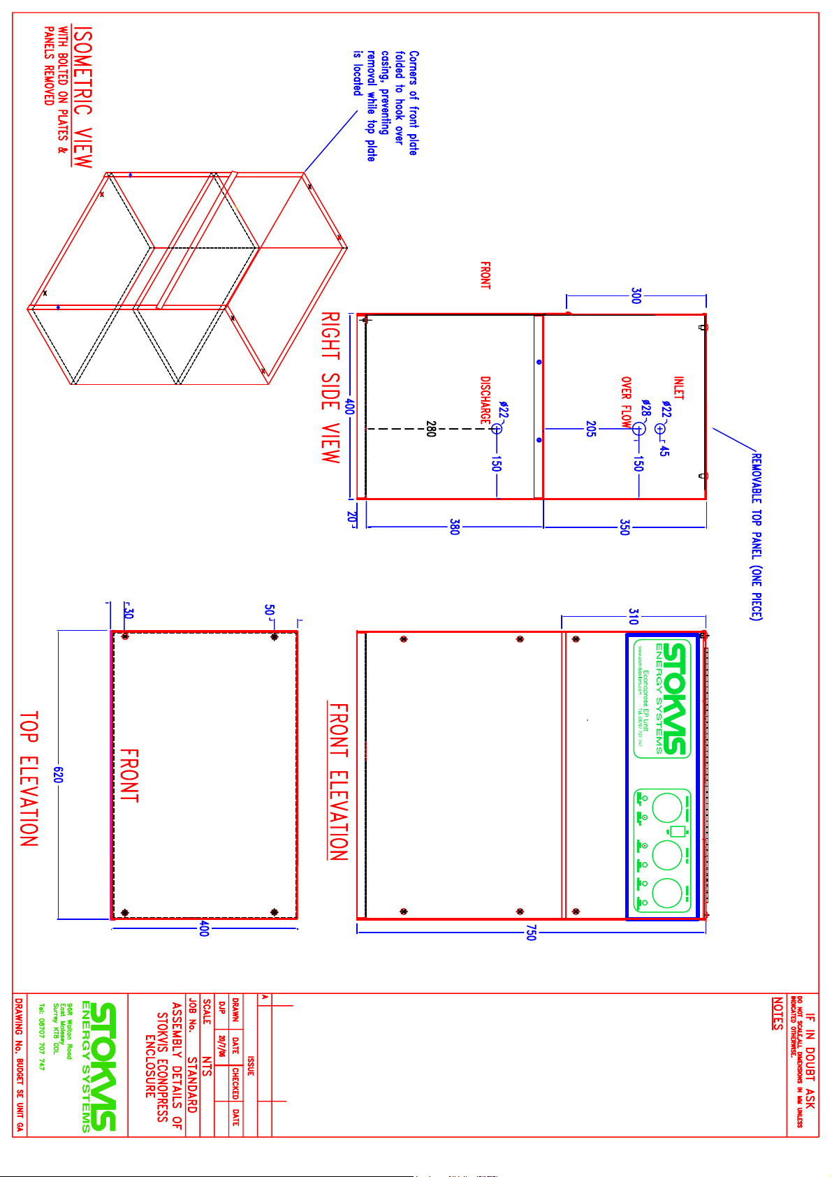
The units comprise a small mains break tank incorporating type ‘A’ air gap, supplied with water via a
ball valve, together with one (EP 1) or two (EP 2) regenerative type pressure pumps, all enclosed in a
purpose built sheet steel enclosure.
The control of the system is by the use of a close differential pressure switch, with a small pre-
charged pressure vessel and a flow-regulating valve.
As the pressure in the system falls below the preset fill pressure, the pressure switch will enabled
duty pump.
The pump will then deliver water to the system, via the flow-regulating valve, thereby raising the
pressure until the cut-out pressure is reached the pump will stop.
The duty pump will auto-rotate per operation in an attempt to achieve even wear on the pumps.
Should the duty pump fail to produce pressure, the standby pump (EP 2 units) will start as the
pressure falls further.
If the pressure, within the system, goes beyond preset design limits, then the system pressure alarm
switches will become activated, illuminating the ‘High Pressure’ or ‘Low Pressure’ lamp on the unit,
and operating a volt free contact (which is usually connected to shut down the burner / chiller).
EP units are available in an enhanced level, if required, incorporating additional control features and
alarms.
Expansion Vessels, which do not form part of the ‘EP’ units, are supplied either individually, or as
part of a complete packaged unit.
They are designed to accept the expanded water from the system, either as the system temperature
rises, in the case of a heating system, or as the system returns to ambient temperature after chilling,
in case of a chilled water system.
This water is held within the vessel, until the system pressure drops, when the expanded water is
forced back into the system by gas pre-charge.
The pressure vessel incorporates a flexible internal diaphragm, which prevents contact between the
gas and water, thus eliminating the need for frequent recharging.

4
Storage.
Units are normally dispatched from the works fully assembled although in some cases, particularly for
export models, certain ancillary parts may be dismantled and packed with the units.
Units will be packed for protection against transit damage, only and must be stored in a dry weather-
protected area, and protected against dust, damp, builder’s debris, etc.
We do not advise leaving the unit outdoors even if sheeted over.
On delivery to site check over the equipment for completeness and damage, but preferably do not
remove the packaging as this will give some degree of protection against site dust etc. Ensure,
however, that the delivery is complete as advised on the packaging note sent with the goods.
Please note that the design of many modern pumps does not always permit effective draining
of test water. It is imperative therefore that units are protected from frost at all times, even
before installation. Stokvis can not accept warranty claims in respect of frost damage.
Installation.
Non-packaged ‘EP’ units can be installed either on a smooth level surface, or alternatively back fixed
to a suitable wall or other vertical structure in areas which are dry, well ventilated and free from any
danger from frost.
Once the unit has been placed in position and fixed, the following connections have to be made.
1) Connect mains water supply to ball valve in tank. The BS1212 part 2 ball valve fitted is of high
pressure type and the water supply should be taken from the rising main or a boosted feed. All new
pipe work should be flushed out before connecting to the unit.
2) Provide an overflow connection from the break tank in accordance with water byelaws.
3) Couple the unit system connection to the system neutral point. This is normally on the return
to the boiler/ chillers, but in the suction side of the circulating pumps if these are mounted on the
return.
The connection must be made through a union and lock shield valve, so that unit can be isolated, if
necessary, and to aid commissioning,
If the unit is supplied as part of a packaged system, then no further connections or valving are
required. However, if the equipment has been purchased as separate components, then each
individual item e.g. EP units and Vessels must be connected to the system as described above, and

5
to suitable isolating valves be incorporated between each individual item of equipment and the
system. In addition, drain cocks must be fitted to enable each individual piece of equipment to be
drained down independently from the main system.
4) Connect a switched fused single phase mains supply at 240volt 1 phase 50hz to the terminals
in the control section of the unit (fused at 13amps).
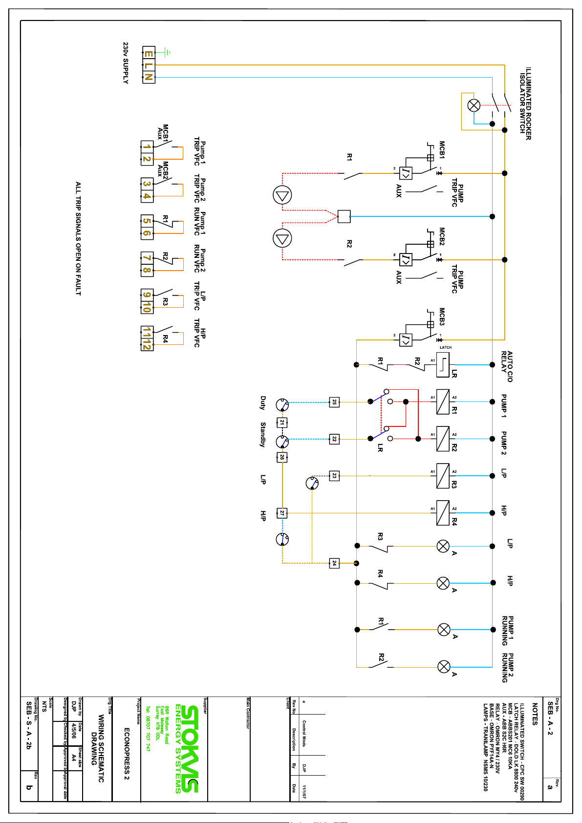
5) Electrical connections will be required to the fault / indication circuits as shown on the wiring
diagram, to which references should be made depending on the option to which the equipment has
been supplied.
All units incorporate a set of volt-free contacts to shut down the burner/chiller on pressure alarm, and
these should be linked into the control circuit, so as to shut down the burner/chiller in the event of an
alarm condition. It is important, however, that the supply to the EP unit is maintained under all
conditions.
Unit.
External pipe work connected to the unit should be supported so as not to stress the pipe work
connections. Any parts removed for transit must be refitted.
The above in conjunction with the drawings should enable the unit to be installed ready for
commissioning, however, if you require advice or assistance please do not hesitate to ask out
technical support staff for guidance.
If Stokvis are commissioning, please ensure that all of the electrical, water and other connections are
intact, and that power and water are available before calling us to site. This will save unnecessary
journeys, delays and expense.
Commissioning.
Before commencing the commissioning procedures detailed below, ensure that the system is full,
and has been vented by using a temporary connection.
This unit is NOT designed for initial system filling, due to its limited flow capacity, but a quick fill
bypass loop is available, and can be supplied (at additional cost) if required.
Ensure that the unit break tank is full to the waterline. Prime the pump by removing the plug at the
top of the pump body, and allowing water to flood through. When all air has been expelled, replace
plug.
Check that the pre-charge pressures in both the unit pressure vessel and the system expansion
vessel (s) are correct.
This check must be carried out with NO water in vessels.

6
Close the isolating valve between the unit and system, and switch on the unit.
The pump should run up to cut-out pressure, and stop.
Crack open the system isolating valve, and observe the pressure gauge on the unit.
Note the pressure at which the pump starts, and adjust this pressure if required to suit the system fill
pressure determined from design data.
Close the system isolating valve.
Lower the pressure within the unit by draining away and note the pressure at which the system low
pressure cut-out switch operates.
Run the pump thereby raising the pressure and note the pressure at which the system high pressure
switch operates.
Check that these pressures are correct, and that the burner / chiller shutdown contacts operate
correctly.
SEB200 units have an additional pump.
On initial switch-on at low pressure, the standby pump will run to cut out pressure and stop,
whereupon the duty pump will start and run to its cut-out pressure.
On falling pressure, the duty pump will start at its cut-in pressure.
Should this pump fail to start the pressure will continue to fall until the standby pump starts.
Note that only one pump ever operates at one time.
Open the valves to the system and switch on.
The unit will run, if required, to bring the system up to the fill pressure.
If the pressure in the system is already higher than the fill pressure, drain water from the system until
the unit runs, then close the drain point, and allow the unit to switch off.
This ensures that the correct fill pressure has been achieved. Commissioning of the unit is now
complete.
Please note that Stokvis cannot accept any warranty claims in respect of units which have not been
commissioned in accordance with the above procedure, nor for units where the settings vary from our
recommendations.

7
Maintenance.
Stokvis EP units have been designed to be easy to maintain, thus ensuring trouble-free operation.
On two pump units the duty pump will automatically rotate per operation, to equalise wear and to
exercise the standby pump.
At regular intervals, but all least every six months, the following points should be checked.
1) Bleed a little water from the system when at ambient temperature, and check that the pump
cut-in and cut-out pressures are as shown in the table of settings attached.
On two pump units continue to bleed water from the system, at a rate greater than approx.
0.75gpm, once the duty pump has started.
This will cause the standby pump to start.
Once the standby pump has started, close the bleed and allow the pressure to rise, noting the
pressure at which the pumps switch off.
If necessary adjust the pressure switch (es) to achieve the correct pressure settings.
Check that the pump(s) run, without excessive noise or vibration and do not leak from the
mechanical seal, either when running or when stationary.
2) Using the isolating valve provided within the unit to isolate the system from the pressure
sensing line, bleed off a few drops of water from the sensing line, having first switched the
pump (s) off.
The pressure within the sensing line will drop, as indicated by the unit gauge.
Check that the switch resets before cold fill pressure is reached.
Close the valve between the unit and system and expansion vessels.
Run the pump, raising the pressure and check that the system high pressure alarm switch
operates at the correct pressure.
Switch off the pump and open isolating valve.
If necessary, adjust the pressure switch (es) to achieve the correct pressure settings.
3) Check the pre-charge pressures in both the unit pressure vessel and system expansion
vessel(s).
Isolate and drain all water from vessels before checking pre-charge pressure at the Schrader
valve, with suitable pressure gauge.
When a checking the pre-charge pressure, note if any water vapour is exhausted from the
Schrader valve.
If this is the case, then the vessel diaphragm has become perforated, and either the
diaphragm (or complete vessel, if it is a fixed diaphragm type), must be replaced.
4) Check over all electrical equipment, checking operation of relays, Mcb’s, lamps, etc.
Check all terminals are tight. Generally clean within the enclosure.
5) Check operation of unit ball valve, ensuring valve will open, and close drip-tight. Lubricate the
fulcrum and/or strip and clean if necessary.
Check inside break tank for any debris or sediment and if necessary drain tank and clean out.
If larger amounts of sediment are found regularly, check the system for leakage.
6) Generally check over and clean the exterior of the unit, at the same time checking for leaks.

8
Spares and service.
For advice or to arrange a commissioning / service visit, or if spare parts are required, please call our
service/repairs department on 08707707747.
Please ask for details on our routine maintenance scheme to ensure that your equipment is
maintained in first class condition.
Always quote the serial number in any communications regarding this unit, as we keep individual
records of all units supplied.
General data EP1 EP1HP EP2 EP2HP
FACTORY SETTINGS
Duty pump cut-in pressure 2.5 BAR 6 BAR 2.5 BAR 6 BAR
Standby pump cut-in pressure N/A N/A 2.3 BAR 5.8 BAR
SE vessel pre-charge pressure 2.3 BAR 5.8 BAR 2.3 BAR 5.8 BAR
Low pressure alarm cut-in pressure .75 BAR 3 BAR 0.75 BAR 3 BAR
High pressure alarm cut-in pressure 3.0 BAR 6.5 BAR 3.0 BAR 6.5 BAR
Pressure Regulating Valve 1.5 BAR 5 BAR 1.5 BAR 5 BAR
Motor full load current (AMPS) 2.2A 3.41A 2.2A 3.41A
Power supply requirements 240/1/50 240/1/50 240/1/50 240/1/50
fused 13A fused 13A fused 13A fused 13A


This manual suits for next models
3
Table of contents
Other STOKVIS ENERGY SYSTEMS Industrial Equipment manuals


