PPI SMART ROLL Troubleshooting guide

OPERATION & MAINTENANCE
SMART ROLL & SMART MONITOR
READ THESE INSTRUCTIONS CAREFULLY BEFORE STARTING INSTALLATION

Smart Roll Selection Guide ............................................................................3
Selecting how many pulses per revolution for the Smart Roll.........................................3
Selecting the Smart Roll Mounting Option and Location .............................................3
Selecting which Smart Monitor to use ..............................................................3
Installing and Mounting the Smart Roll .................................................................4
Clean Side Return Mounting Instructions. . . . . . . . . . . . . . . . . . . . . . . . . . . . . . . . . . . . . . . . . . . . . . . . . . . . . . . . . . . . 4
Setting up the pivot/hinge..........................................................................4
Test Fit the Mounting Assembly ....................................................................5
Final Installation of the Mounting Assembly .........................................................5
Pivot / Hinge Option 1: Welding pivot rod to conveyor frame .........................................6
Pivot / Hinge Option 2: Use of mounting brackets ...................................................6
Clean Side Return Smart Roll Diagram & Parts List..................................................7
Wiring the Smart Roll..................................................................................8
Wiring the Smart Monitor..............................................................................9
Smart Monitor Set-up ................................................................................ 12
Trip Point Set-up.................................................................................. 12
Ramp-up Timer Set-up............................................................................ 12
Testing Procedure ................................................................................ 12
Adjust Ramp-up Timer after Smart Monitor is Installed and Wired into Control Circuit ............... 12
Using a PLC ......................................................................................... 13
What is a Pulse? ..................................................................................13
What is the Pulse Duration and calculating Pulse Duration? ........................................ 14
What if the pulses are too fast for my electronics? .................................................. 14
Converting pulses to belt speed? .................................................................. 14
Frequently Asked Questions:. . . . . . . . . . . . . . . . . . . . . . . . . . . . . . . . . . . . . . . . . . . . . . . . . . . . . . . . . . . . . . . . . . . . . . . . . . 15
Appendix .............................................................................................17
Universal Mount Smart Roll ........................................................................17
Universal Mount Smart Roll Mounting Instructions: ..................................................17
Universal Mount Smart Roll Wiring: .................................................................17
Universal Mount Smart Roll Diagram & Parts List:.................................................. 18
Troughing Smart Roll ............................................................................. 19
Troughing Smart Roll Mounting Instructions: ....................................................... 19
Troughing Smart Roll Wiring: ...................................................................... 19
Troughing Smart Roll Diagram and Parts List:......................................................20
Return Smart Roll ................................................................................. 21
Return Smart Roll Mounting Instructions: .......................................................... 21
Return Smart Roll Wiring: ......................................................................... 21
Return Smart Roll Diagram & Parts List: ...........................................................22
Smart Roll Sensor Wiring Diagrams and Specifications .............................................23
Additional Smart Monitors.........................................................................24
Part number 37545 Smart Monitor 120VAC 4-20mA output .........................................24
Part number 47268 Smart Monitor 9-36 VDC ......................................................26
Part number 47269 Smart Monitor 220VAC 4-20mA output.........................................28
Part Numbers.....................................................................................30
Smart Monitor Part Numbers ......................................................................30
Clean Side Return Smart Roll Part Numbers .......................................................30
Universal Mount Smart Roll Part Numbers .........................................................30
Troughing Equal Smart Roll Part Numbers ......................................................... 31
Flat Return Smart Roll Part Numbers ..............................................................32
TABLE OF CONTENTS

3
SMART ROLL SELECTION GUIDE
The Smart Roll needs to be used with a Smart Monitor, PLC, or similar device that can monitor the pulses and select a desired output.
Read the complete manual and understand all wiring, pulse selection, and mounting instructions prior to installation. Refer to the sections
Pulse Selection and Frequently Asked Questions of this manual. If necessary contact a PPI Applications Engineer.
The Smart Roll and Smart Monitor should be installed by trained personnel using appropriate safety practices per the National Electric
Code, including electrical disconnect and lockout practices reference ANSI Z244.1. This device is not intended for use in hazardous areas
as defined by the NEC articles 500-504. Intrinsically Safe Smart Rolls and Smart Monitors are not presently available. Follow all procedures
for power disconnect, lockout-tagout, mechanical blocking, etc. to ensure safety.
SMART ROLL SELECTION GUIDE
SELECTING HOW MANY PULSES PER REVOLUTION
FOR THE SMART ROLL
The PPI Smart Roll is a preset sensor switch. As the roll rotates,
an electrical circuit is opened and closed to create pulses. It is
available in options of 1, 2, or 6 pulses per revolution. The most
commonly used is the 2 pulse option. Belt speed, roll diameter,
and electronics capabilities are selection considerations. Using
the lowest number of pulses per revolution will maximize the time
duration of each pulse. The Clean Side Return SAD5CSRSB-2PL4
is the most versatile and most commonly used Smart Roll. Table 1.1
is based on using a Smart Monitor and the Clean Side Return Smart
Roll using a 5 inch diameter roll. The actual speed limitations may
differ from these limits depending on the roll diameter and electronics.
SELECTING THE SMART ROLL MOUNTING OPTION AND LOCATION
The Smart Roll is available in 4 mounting options, and can fit most locations on a conveyor.
1. Clean Side Return (CSR) – Preferred
2. Universal Mount – An 11.125” long roll in a mounting bracket with two slots for mounting.
3. Return Roll positions in CEMA C and D sizes. Belt widths from 24-60 inches.
4. Troughing Idler (wing roll only) positions in CEMA C and D sizes. Belt widths from 24-60 inches.
In order for the Smart Roll to provide reliable feedback follow these guidelines:
• The roll must maintain belt contact at all times. Areas with high vibration should be avoided.
• Avoid areas where material can build up on the roll. This can increase the roll diameter
and cause errors.
• Select an area and location where the Smart Roll will be best protected from abuse.
• PPI typically recommends the Clean Side Return (CSR) mounting option.
• The next best option is typically the Universal Mount.
• Mounting the Smart Roll in a troughing frame or return position should be considered
as a last option.
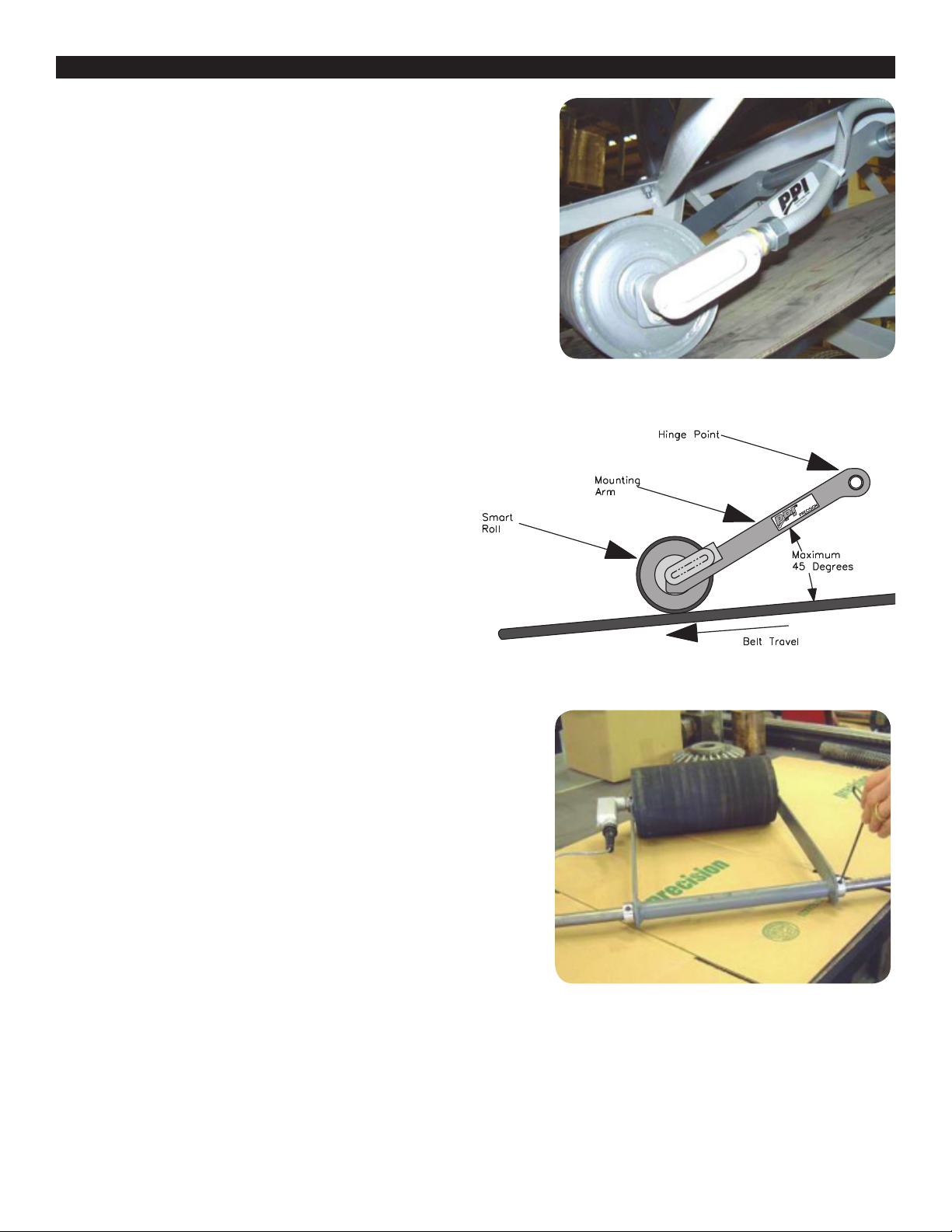
• The CSR is the most commonly used Smart Roll (see picture). This Operation and Maintenance
Manual uses this model when explaining the installation and wiring.
SELECTING WHICH SMART MONITOR TO USE
Several models of the Smart Monitor are available. The most commonly used is part number 37543
Smart Monitor 120VAC. This Operation and Maintenance Manual uses this model when explaining
the installation and wiring.
• 37543 Smart Monitor 120VAC; Relay Contacts
• 37545 Smart Monitor 120VAC 4-20mA output
• 47268 Smart Monitor 9-36 VDC; Relay Contacts
• 47269 Smart Monitor 220VAC 4-20mA output
Attention must be given to the location of the Smart Roll so that it is always in contact with the belt. Failure to mount properly may void
warranty and could cause damage to conveyor belt and other components.
# PULSES
SPEED FEET
PER MINUTE
MIN
SPEED
FPM
MAX
RANGE APPLICATION
6 5 700 Low Feeders/Metering
2 10 2000 Normal Normal
1 20 4000 High High Speed
TABLE 1.1 – Smart Roll Speed Limitations
4
Please note, care must be taken to avoid scraped, pinched, or crushed
wiring. Wires that are scraped, pinched, or crushed during shipping,
handling or installation will void the warranty.
Installing the Clean Side Return (CSR) Smart Roll is shown to the right.
This is the most commonly used Smart Roll. For mounting the Universal,
Trougher or Return Smart Rolls see the appendix.
CLEAN SIDE RETURN MOUNTING INSTRUCTIONS
Setting up the pivot/hinge
Typically, the CSR is mounted on the clean side of the belts return run
using a ¾ inch diameter rod as a pivot or hinge. Figure 2.1 shows a typical
installation for a Clean Side Return Smart Roll on the clean side of the
return run of the belt. Care must be taken to select a location allowing
free movement of the CSR hinge, see Figure 2.2. Mounting the CSR in
locations restricting free movement of the roll and/or mounting arm may
cause premature failure and void the warranty. CSR should not be used on
a reversing belt. The angle from the belt to the CSR mounting arm should
not exceed 45 degrees as shown in Figure 2.2. Proper orientation with belt
travel direction, as shown, is critical. Severe roll and/or belt damage
may occur if mounted incorrectly.
Two options are shown for mounting the CSR Smart Roll. Option 1 is
welding the pivot shaft to the conveyor frame work and option 2 is
using mounting brackets bolted to the frame work. Diagrams for the
pivot/hinge options are shown at the end of this section.
Option 1: At the conveyor mounting location, measure the distance
between the conveyor framework where the ¾ inch diameter shaft
will be attached. Cut the shaft to length, removing burrs, and all
sharp edges.
Option 2: At the conveyor mounting location, measure the distance
between the conveyor framework where the holes will be located for
the mounting brackets. This measurement will determine which mounting
bracket hinge option to use.
Options 1 & 2: Insert the ¾ inch diameter shaft through the CSR hinge
point. Center the shaft with the hinge point, and install one retaining collar
on each end of the shaft as shown in Figure 2.3. Turn shaft collars so set
screws are aligned and lightly tighten the set screws.
FIGURE 2.1: Clean Side Return roll in a typical installation. Optional
CSR mounting hardware shown. Conduit and wire tire not included.
FIGURE 2.2: CSR Mounting
FIGURE 2.3: CSR Mounting Accessories test fit in CSR hinge point.
CSR Mounting Accessories sold separately.
INSTALLING AND MOUNTING THE SMART ROLL
5
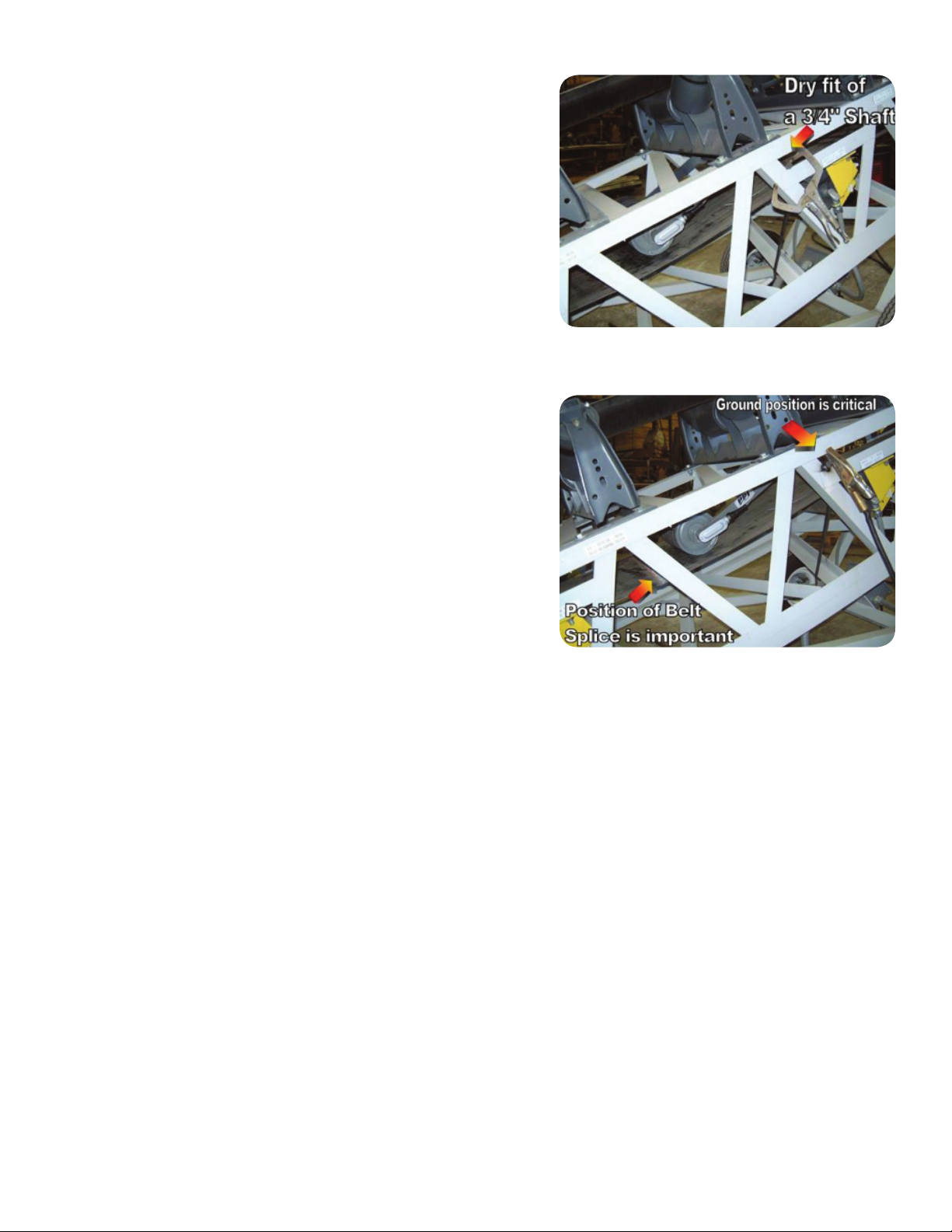
Test Fit the Mounting Assembly
Option 1: Test fit the CSR and Mounting assembly in the conveyor
framework before doing the final installation. Place the CSR and Mounting
assembly in conveyor framework as shown in Figure 2.4. Be sure the
travel direction and path of the wire and/or conduit is correct, and that the
set screws are accessible. The Smart Roll should be in the center of the
belt. Check to make sure the roll is free to rotate and mounting arm is
free to pivot through its full range of motion. If there are any obstructions,
move the CSR and Mounting assembly out of the way and make the
necessary adjustments.
Option 2: Install both mounting brackets to the conveyor framework. One
bracket will be installed on each side of the belt with slots facing upward
and toward the center of the belt. Holes might be needed in the structure
for attaching the brackets.
Option 1 & 2: Move both collars to within 1/8 inch of CSR hinge and
tighten securely.
Final Installation of the Mounting Assembly
Option 1: Prepare the site for welding the ¾ inch diameter shaft to the
conveyor framework by providing adequate protection for the belt and
other components. Welding to be performed by qualified individuals
trained to AWS, or equivalent. PPI is not capable of being aware of all site
specific and industry welding requirements for an application, and cannot
be held liable for non-compliant installations. Proper weld ground location
is critical to prevent damage to bearings and sensor inside the Smart Roll.
These components will not tolerate welding current through them and will
be permanently damaged. Improper ground placement will void warranty.
Figure 2.5 shows a typical welding set-up. Weld ground is placed in a
location keeping the flow of current away from the roll. Keep the belt
splice at least six inches away from the Smart Roll to further reduce the
chance of welding current damage.
When welding is completed remove welding protection, clamps, welding
ground, and any other objects used in installation. Clean weld area and
provide paint or other protective coating per accepted site practice.
Option 2: With the ¾ inch diameter rod installed in the CSR hinge, slide
the slots at the ends of the rod into the slots on the brackets. On each
end of the shaft install the teardrop shaped end clip over the end of the
shaft. Then install the screw into the hole in the end clip and bracket. This
is a self-threading screw; take care not to strip the threads on the screw
or the hole in the bracket.
FIGURE 2.4: Test fit of CSR and Mounting Accessory assembly in
conveyor framework, typical both sides.
FIGURE 2.5: Permanent attachment of 3/4 inch shaft to framework.
Component protection for welding has been removed for clarity.

6
PIVOT / HINGE OPTION : WELDING PIVOT ROD TO CONVEYOR FRAME
PIVOT / HINGE OPTION : USE OF MOUNTING BRACKETS
ASSEMBLIES
CARBON STEEL
ASSEMBLY PART #
STAINLESS STEEL
ASSEMBLY PART #
42971 42971S4
42972 42972S4
COMPONENTS 4 FEET LONG – CARBON STEEL
ITEM QTY DESCRIPTION PART #
1 1 3/4” diameter x 4’ long rod 43180
2 2 Shaft Collar SC0012
COMPONENTS 7 FEET LONG – CARBON STEEL
ITEM QTY DESCRIPTION PART #
1 1 3/4” diameter x 7’ long rod 43181
2 2 Shaft Collar SC0012
COMPONENTS 4 FEET LONG – STAINLESS STEEL
ITEM QTY DESCRIPTION PART #
1 1 3/4” diameter x 4’ long rod 43180S4
2 2 Shaft Collar - Stainless Steel SC0012S4
COMPONENTS 7 FEET LONG – CARBON STEEL
ITEM QTY DESCRIPTION PART #
1 1 3/4” diameter x 7’ long rod 43181S4
2 2 Shaft Collar SC0012S4
12
12
3
4
5
COMPONENTS – CARBON STEEL RODS
ITEM QTY DESCRIPTION PART #
1 1 3/4” diameter rod TABLE
2 2 Shaft Collar SC0012
3 2 1-1/2” End Stand 15001
4 2 C End Clip 31790
5 2 #12-3/8” Self Tapping Screw 31880
COMPONENTS – STAINLESS STEEL RODS
ITEM QTY DESCRIPTION PART #
1 1 3/4” diameter rod TABLE
2 2 Shaft Collar SC0012S4
3 2 1-1/2” End Stand 15001
4 2 C End Clip 31790
5 2 #12 x 3/8 Self Tapping Screw 31880
ASSEMBLIES WITH RODS – STAINLESS STEEL
ASSEMBLY
PART #
SHAFT
PART #
SHAFT
LENGTH (HC) BE LT
WIDTH
CSR-24S4 43521S4 28.625 33.0 24
CSR-30S4 43522S4 34.625 39.0 30
CSR-36S4 43523S4 40.625 45.0 36
CSR-42S4 43524S4 46.625 51.0 42
CSR-48S4 43525S4 52.625 57.0 48
CSR-54S4 43526S4 58.625 63.0 54
CSR-60S4 43527S4 64.625 69.0 60
CSR-66S4 43528S4 70.625 75.0 66
CSR-72S4 43529S4 76.625 81.0 72
CSR-78S4 43670S4 82.625 87.0 78
CSR-84S4 43671S4 88.625 93.0 84
CSR-90S4 43672S4 94.625 99.0 90
CSR-96S4 43673S4 100.625 105.0 96
ASSEMBLIES WITH RODS – CARBON STEEL
ASSEMBLY
PART #
SHAFT
PART #
SHAFT
LENGTH (HC) BE LT
WIDTH
CSR-24 43521 28.625 33.0 24
CSR-30 43522 34.625 39.0 30
CSR-36 43523 40.625 45.0 36
CSR-42 43524 46.625 51.0 42
CSR-48 43525 52.625 57.0 48
CSR-54 43526 58.625 63.0 54
CSR-60 43527 64.625 69.0 60
CSR-66 43528 70.625 75.0 66
CSR-72 43529 76.625 81.0 72
CSR-78 43670 82.625 87.0 78
CSR-84 43671 88.625 93.0 84
CSR-90 43672 94.625 99.0 90
CSR-96 43673 100.625 105.0 96
12
12
3
4
5
7
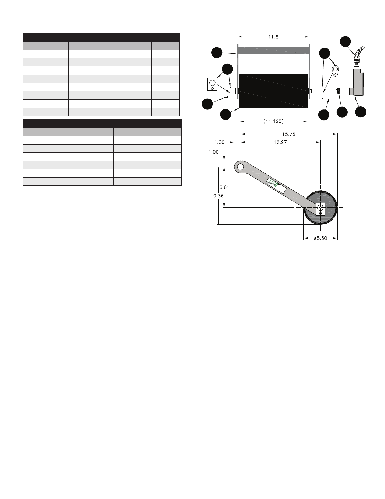
CLEAN SIDE RETURN SMART ROLL DIAGRAM & PARTS LIST
ASSEMBLY COMPONENTS
ITEM QTY DESCRIPTION PART #
1 1 Smart Roll TABLE
2 1 CSR Bracket 40820
3 1 D End Clip 47117
4 2 #12-3/8” Self Tapping Screw 31880
5 1 B End Clip 31800
6 1 Hex Bushing 34461
7 1 90º Elbow Conduit Access Port 34452
8 1 Strain Relief Fitting 40824
CSR SMART ROLLS
ROLL Ø ASSEMBLY PART # ROLL ONLY PART #
5.5 SAD5CSRSB – 1PL4 SAD5TE30SB – 1PL4
5.5 SAD5CSRSB – 2PL4 SAD5TE30SB – 2PL4
5.5 SAD5CSRSB – 6PL4 SAD5TE30SB – 6PL4
6.5 SAD6CSRSB – 1PL4 SAD6TE30SB – 1PL4
6.5 SAD6CSRSB – 2PL4 SAD6TE30SB – 2PL4
6.5 SAD6CSRSB – 6PL4 SAD6TE30SB – 6PL4
2
3
4
1
5
8
7
6
4

8
1. Disconnect and lockout power before starting wiring procedure.
The CSR Smart Roll is provided with a ½ inch 90° elbow conduit access port and a strain relief. The Smart Roll cable is 2 wire, 22
AWG, PVC jacket, PVC insulation, and 6 feet in length. No set-up is required to the sensor inside the Smart Roll. It is factory set and
maintenance free.
DO NOT apply voltage directly across the wires of the Smart Roll Sensor, permanent damage may result. The Smart Roll is designed to
be used with a Smart Monitor, PLC, or similar device.
DO NOT use an incandescent light bulb as a load. An overload will occur due to extremely high cold current.
DO NOT operate without a load. A dead short will result which may cause irreparable damage.
DO NOT directly operate a motor with the sensor. Always use a relay or other appropriate device.
2. At this point a 2 wire cable needs to be routed from the control box housing the Smart Monitor to the Smart Roll. It is recommended to
use minimum of 22 AWG shielded cable. Shielded cable eliminates electromagnetic interference (EMI). It is advisable to route the wires/
conduit for the Smart Roll away from electrical power conduit as the electrical power may cause electromagnetic interference (EMI) in the
signal from the Smart Roll. If EMI is present the signal from the Smart Roll may not make it to the Smart Monitor or PLC. This will result in
the Smart Monitor or PLC getting faulty readings.
Conduit from the control box to the Smart Roll offers more protection to the cable. Any nick, gouge, or cut in the cable wiring could
prevent the sensor signal from reaching the Smart Monitor.
If flexible conduit is used then the strain relief is not needed and can be removed. PPI recommends the wires or flexible conduit be
routed along the side of the CSR bracket and towards the hinge point. This will allow for free motion of the hinge. Be sure the wires or
conduit will not hinder the pivoting of the smart roll.
PPI is not capable of being aware of all site and industry electrical requirements for an application, and cannot be held liable for
non-compliant installations. The product has been designed to be capable of meeting many requirements, and a qualified individual should
review the connection plan prior to installation. Connection of conduit to 90° elbow conduit access port does not meet intrinsically safe
requirements.
DO NOT PULL THE WIRES CONNECTED TO THE SMART ROLL. Pulling wire from inside the roll will cause damage and void warranty. Be
sure to protect the wire near elbow threads and all corners, as this may damage the wire/insulation.
3. Remove the cover from the 90° elbow conduit access
port and route the Smart Roll wires and the wires from
the control box through the conduit opening in the 90°
elbow access port and out the rectangular opening.
4. Attach the conduit to the 90° elbow access port.
5. Attach the Smart Roll wires to the wires from the control
box. Cut wires to proper length to fit in junction box. DO
NOT apply power to the sensor at this time. The Smart
Monitor or PLC provides the power for the Smart Roll.
To avoid damage, verify the circuit meets the sensor
specifications shown in Section A4 prior to applying
power.
6. Reinstall junction box lid and tighten screws to secure.
FIGURE 3.1: 90° Elbow Conduit Access Port.
WIRING THE SMART ROLL

9
The Smart Monitor provides an under speed switch by monitoring 6-3,000 pulses per minute
(PPM) and has a user-programmable 0-30 second ramp-up timer. The Smart Monitor is
designed to be located in an electrical panel or O.E.M. control box. A removable plate allows for
mounting to a DIN rail. The digital display shows the current PPM in real time. This eliminates
setting “guesswork” by constantly showing the actual PPM being monitored.
The digital display shows “RPM” next to the monitored speed. This can be misleading with a 2 or
6 pulse Smart Roll, as the monitor is actually displaying pulses per minute (PPM).
As with any electrical equipment, the Smart Monitor should be installed by trained personnel
using appropriate safety practices per the National Electric Code, including electrical disconnect
and lockout practices reference ANSI Z244.1.
This device is not intended for use in hazardous areas as defined by the NEC articles 500-504.
Intrinsically Safe Smart Monitors are not presently available.
Several models of the Smart Monitor are available. This section will show wiring for the 120VAC
model part number 37543.
Specification – 37543 Smart Monitor 120VAC
• AC Input: 120 VAC 10 W
• Fuse Protected: 1 amp
• Speed Range: 6-3000 pulses per minute
• Relay Contacts: DPDT 5 amp @ 120VAC
• Safety Delay: 1 second
• Response Time: 1 second or less
Additional models of the Smart Monitor are available.
Specifications for these are shown in the appendices:
• Part number 37545 Smart Monitor 120VAC 4-20mA output
• Part number 47268 Smart Monitor 9-36 VDC
• Part number 47269 Smart Monitor 220VAC 4-20mA output
1. Mount the Smart Monitor inside and existing control panel or other suitable
protective enclosure. See Figure 4.1 for Smart Monitor mounting dimensions.
2. Disconnect AC power before proceeding with installation.
3. Table 4.2 shows connection details for the terminal strip.
FIGURE 4.1: 37543 Smart Monitor dimensions.
TERMINAL CONNECTION
FRONT
1NO CONNECTION
2NO CONNECTION
3NO CONNECTION
4NO CONNECTION
5NO CONNECTION
6NO CONNECTION
7Sensor Input (+)
8Sensor Input Common (-)
BACK
9N/C (2)
10 Common (2)
11 N/O (2)
12 N/C (1)
13 Common (1)
14 N/O (1)
15 AC Input (N)
16 AC Input (H)
FIGURE 4.2:
37543 Smart Monitor terminal connections.
WIRING THE SMART MONITOR
10
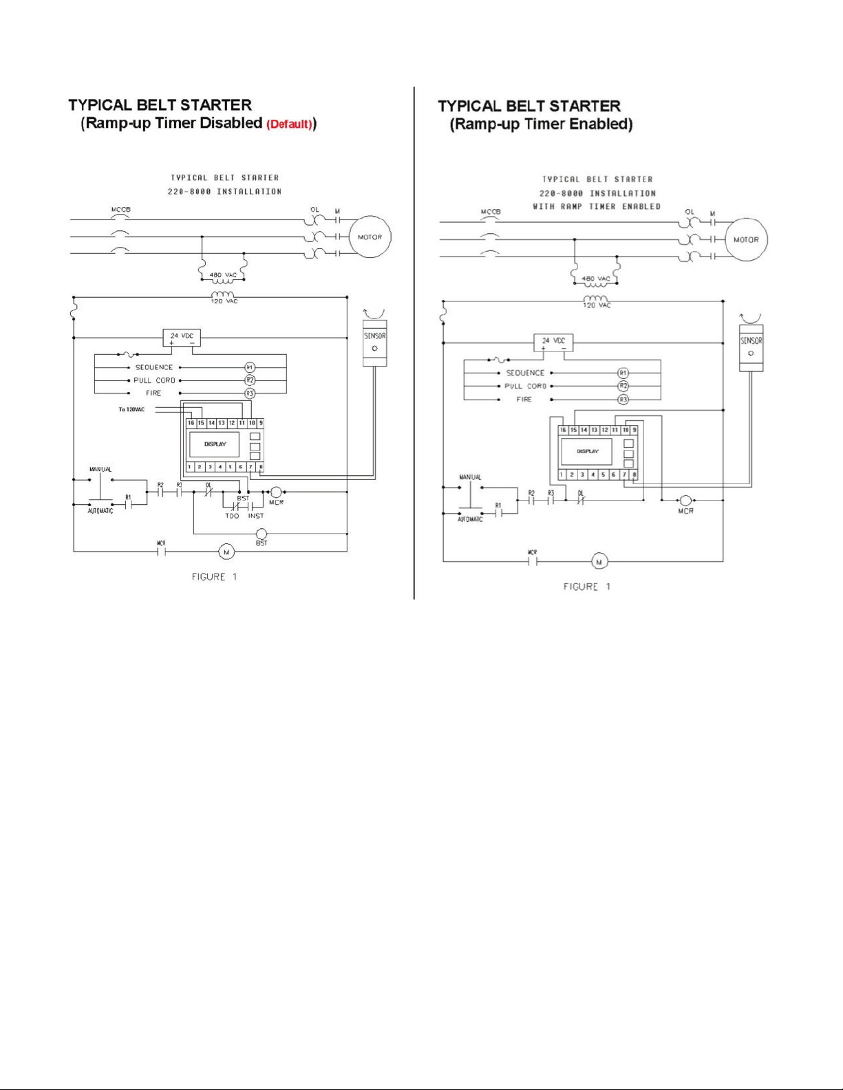
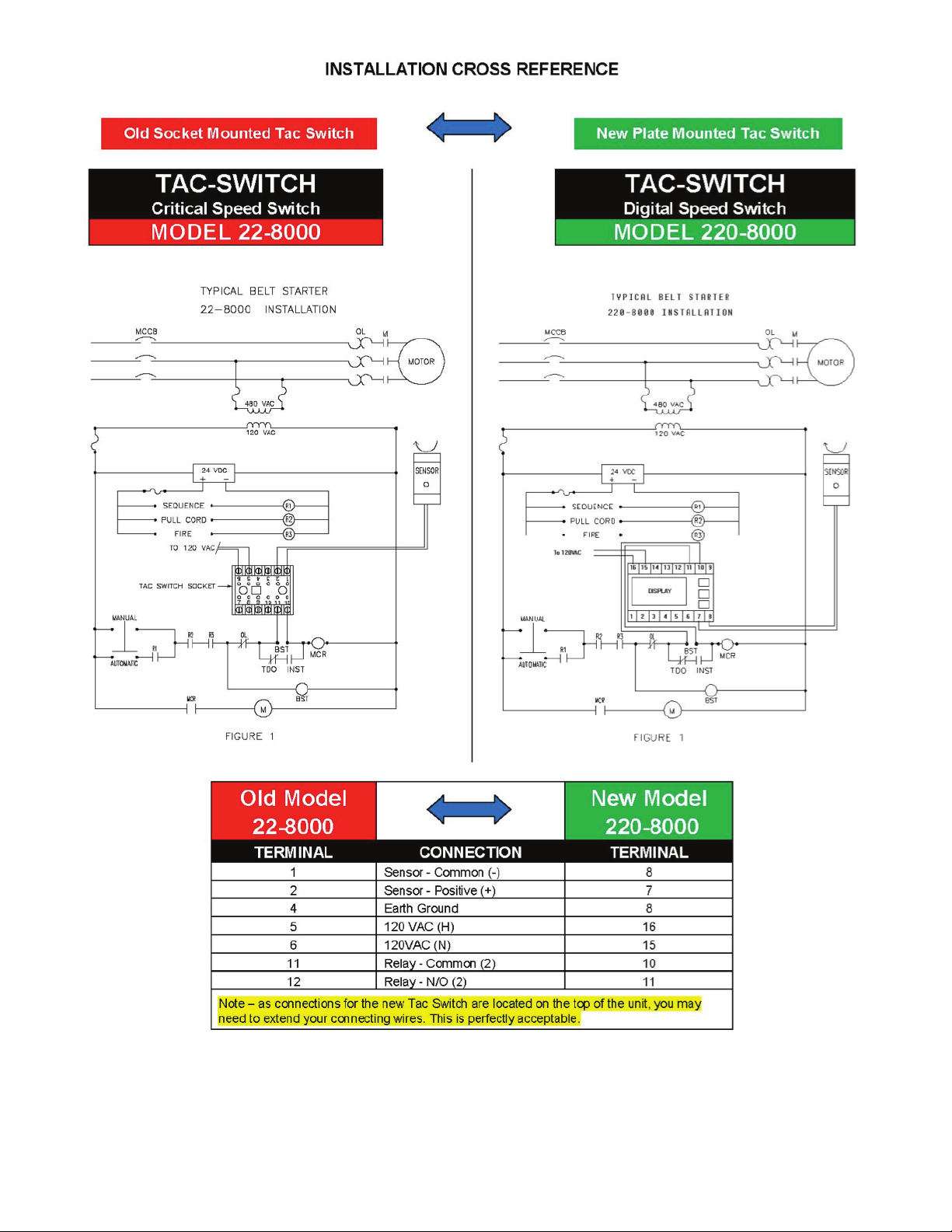
4. Figure 4.3 shows a sample wiring diagram of how the Smart Monitor can be wired into your system. If you are familiar with PPI’s older
Smart Monitor see Figure 4.4 comparing the wiring diagrams on the next page.
5. Connect Smart Roll wires to terminals 7 and 8. Polarity of the wires is not important.
6. Connect the wiring for the 120 VAC to terminals 15 and 16 to power the Smart Monitor.
The Smart Monitor provides the power for the Smart Roll through terminals 7 and 8.
7. Terminals 9 through 14 are customer contacts to be used for system control.
8. Remove lockouts and apply power to the Smart Monitor.
11
Figure 4.4: Installation cross reference for old and new Smart Monitors.

12
TRIP POINT SETUP
Apply power to the Smart Monitor. If this is the first time powering the unit up, the default trip point is 6 RPM or PPM, the built-in ramp-up
timer is disabled and the relay is off (TRIP: 0006 / RAMP: 0S / REL: OFF). Read through the following instructions before starting the
set-up procedure.
1. Momentarily depress the down arrow button once to highlight “TEST.”
2. Momentarily depress the down arrow a second time to highlight “TRIP.”
3. Momentarily depress the SET button to begin setting unit to the trip speed desired, starting with the 4th digit (the 1000s place). When
highlighted, use the up/down arrow buttons to change number as needed. When 4th place is set correctly, momentarily depress the
SET button to begin setting the 3rd (100s place) digit. Again use the up/down arrow buttons to change the number. When set correctly,
momentarily depress the SET button to begin setting the 2nd (10s place) digit. Use up/down arrow buttons as before to change the
number, and once set, momentarily depress the SET button to begin setting the 1st and final digit. The selection will time out and reset
after approximately 15 seconds with no new input.
5. Review your settings for accuracy. If a digit needs to be adjusted, momentarily depress the SET button one or more times to get to the
proper digit, then use the up/down arrows to switch number and when satisfied, press and hold the SET button – the RPM setting will
highlight and then go back to normal. The SET button can then be released. The RPM setting will be maintained in non-volatile memory
until changed by the operator.
RAMPUP TIMER SETUP
The default setting for the ramp-up timer is 0 seconds (timer disabled). To set the timer for a 1 to 30 second ramp-up period, follow the
procedure below:
1. Momentarily depress the down arrow to highlight “RAMP.”
2. Momentarily depress the SET button to highlight the timer in seconds.
3. Use the up/down arrow buttons to increment the timer from 0 seconds up to a max of 30 seconds. The selection will time out and reset
after approximately 15 seconds with no new input.
When satisfied, press and hold the SET button – the timer setting will highlight then return to normal.
TESTING PROCEDURE
1. A test function has been provided to allow the operator to de-energize the internal control relay and stop the monitored equipment. To
activate a test shutdown,
2. Momentarily depress the down arrow button once to highlight “TEST.”
3. Depress and HOLD the SET button for approximately 3 seconds – the control relay will de-energize.
4. Release the SET button. There is a safety delay that will keep the control relay off for 10 seconds after it has de-energized.
5. The relay will automatically re-energize after the delay if RPM above the programmed trip point is detected.
ADJUST RAMPUP TIMER AFTER SMART MONITOR IS INSTALLED AND WIRED INTO CONTROL CIRCUIT
There may be times when after installation the ramp-up timer is found to be set too short a period of time. This presents a problem
because when the equipment being monitored is shut down, there is also no power going through the Smart Monitor. The following
procedure should be performed to allow setting of the ramp-up timer on the next equipment start-up cycle:
1. Before starting the monitored equipment, depress and hold the SET button until the equipment start-up sequence has been initiated –
the display of the Smart Monitor will be powered on, “RAMP” will be highlighted and the control relay (REL) will be “ON” (energized).
2. Release the SET button then use the up arrow button to increment the ramp-up timer to the desired number of seconds
(max of 30).
3. Depress and release the SET button to “write” the new ramp-up timer setting in to the Smart Monitor. The new setting will be used on
the next equipment start-up sequence.
SMART MONITOR SETUP
13
The Programmable Logic Controller (PLC) and Smart Roll work together to give the desired output. Typically the pulses from a Smart Roll
are read by a PLC and converted to a speed output. This speed output can then be used by the PLC to create actions, such as shutting
down a conveyor due to an under speed condition.
If the roll is rotating too fast or the PLC is not sampling often enough, the output will not work as desired. There are specifications you
will need to know about your conveyor setup, PLC, and Smart Roll sensor. These specifications are belt speed, outside diameter including
lagging of the Smart Roll, pulses per revolution of the Smart Roll, sampling rate of the PLC and/or the minimum sample duration, and
power supplied to the sensor from the PLC.
The Smart Roll sensor has a maximum switching frequency of 20 Hz, or 20 pulses per second. Digital electronic equipment, such as a PLC,
takes intermittent sensor readings rather than continuously monitoring the sensor. If the switching of the sensor pulses is faster than the
sampling rate of the equipment, errors may occur. Marginal cases may have erroneous speed output from missed pulses, and extreme
cases may cause a complete lack of output.
WHAT IS A PULSE?
As the roll rotates, it opens and closes an electrical circuit to create pulses a preset number of times per revolution. One pulse is defined as
one complete on/off cycle.
Examples:
6 pulses per revolution the sensor creates 6 on/off cycles, or pulses for each revolution.
2 pulses per revolution the sensor creates 2 on/off cycles, or pulses for each revolution.
1 pulse per revolution the sensor creates 1 on/off cycles, or pulses for each revolution.
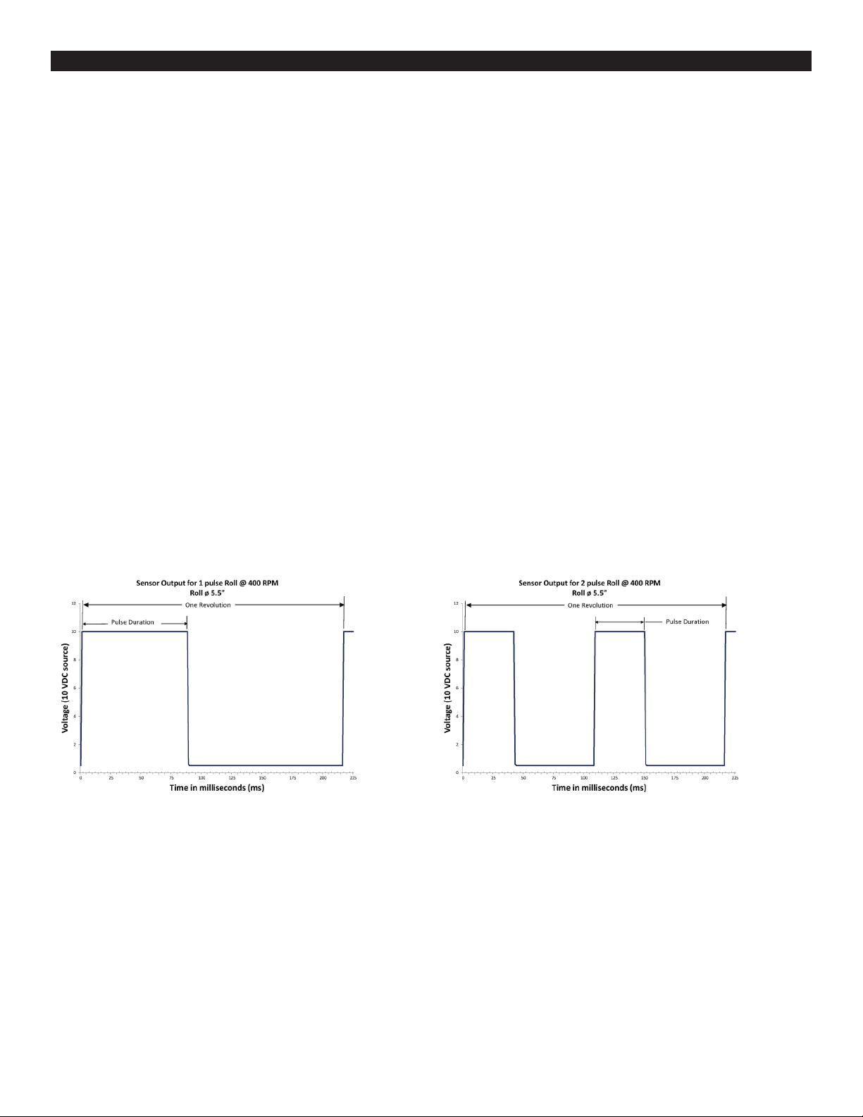
The 1 and 2 pulse options have fewer pulses and greater pulse duration, i.e. the pulse will have a greater width on the chart. Figures 6.1 and
6.2 show pulses using 400 feet per minute belt speed, Smart Roll part numbers SAD5CSRSB-1PL4, and SAD5CSRSB-2PL4 respectively.
WHAT IF THE PULSES ARE TOO FAST FOR MY ELECTRONICS?
USING A PLC
Figure 6.1: Example sensor output for a 1 pulse roll,
P/N SAD5CSRSB-1PL4
Figure 6.2: Example sensor output for a 2 pulse roll,
P/N SAD5CSRSB-2PL4

14
There are several options in this case.
• Select a roll with a lower number of pulses per revolution. If you are using a Smart Roll with 6 pulses per revolution, switch to a 2
pulse or 1 pulse per revolution Smart Roll. The PLC will have more time between pulses and longer pulse duration. This is the preferred
method.
• Reprogram the PLC or electronics to a faster sampling rate and/or longer sampling durations.
• Change to a larger diameter roll. If you are using a 5” diameter Smart Roll without lagging, switch to a roll with ¼” of lagging to make
the Smart Roll 5.5” diameter, or switch to a 6” diameter Smart roll with or without lagging.
CONVERTING PULSES TO BELT SPEED?
The following equation can be used to convert Smart Roll pulses to belt speed.
D = Roller Outside Diameter including lagging, in inches.
count = Number of pulses counted in the sampling time period.
Time = Sampling time period in seconds.
#pulse = Number of pulses per revolution of the Smart Roll (1, 2, or 6).
fpm = belt speed in feet per minute.
Duration = 0.85 = 0.85
7.854 (D)
fpm (#pulse) – 0.004
(
)
π(D) 60
fpm (#pulse)12 – 0.004
(
)
x1
2
fpm = =
15.708 (count) (D)
Time (#pulse)
(
)
π(count) (D) 60
Time (#pulse)12
(
)

15
WHAT IS A PPI SMART ROLL?
The PPI Smart Roll is a PPI idler roll with a sensor built inside the roll. All the components inside the roll are aligned, ready to use, and
maintenance free. As the roll rotates the sensor opens and closes a circuit to produce on/off pulses. Additional electronics such as the
Smart Monitor or PLC are needed to convert these pulses into a usable function.
WHY IS THE CLEAN SIDE RETURN CSR PREFERRED?
More versatile: Because the CSR is independent of the belt width it can reduce your spares inventory. Putting Smart Rolls into troughing
or return positions can cause increased inventory expenses because each belt width requires a different Smart Roll spare.
Lasts longer: The CSR Smart Roll practically eliminates load on the roll because it does not support the weight of the belt or material.
The CSR is more forgiving in dirty environments. The CSR can be mounted in a protected location. The CSR Mounting bracket is designed
to rotate so that if material gets between the roll and belt it is free to roll over the debris. The use of CSR is not recommended for
reversing belts.
WHAT IS A PPI SMART MONITOR?
The PPI Smart Monitor is used to convert the pulses from the Smart Roll into a usable form. Using the Smart Monitor a critical speed
is set, when the speed falls below the set point the Smart Monitor will energize a relay. The relays can then be wired into the conveyor
controls. The Smart Monitor also has a ramp up timer that can be set from 0 seconds up to 30 seconds.
IS A PPI SMART MONITOR REQUIRED WHEN USING A PPI SMART ROLL?
A Smart Monitor, PLC, or other similar device is required to read the Smart Roll pulses and convert them into a usable form.
CAN A PLC BE USED WITH THE PPI SMART ROLL?
Yes, the Smart Roll uses an inductive proximity sensor capable of handling most situations. It is normally open and can be wired in a
20-250 VAC or 10-300 VDC circuit.
IS IT POSSIBLE TO TEST THE SMART ROLL SENSOR BEFORE IT IS INSTALLED?
Yes. The test equipment must be able to apply power and detect when the circuit is opened and closed. There are several sensor testers
on the market; Contrinex, HTM and others make sensor testers that can test the Smart Roll sensor.
IS IT POSSIBLE TO TEST THE ROLL AFTER IT IS INSTALLED ON THE CONVEYOR?
Yes. Using a sensor tester mentioned above, the Smart Roll must be disconnected from the Smart Monitor or PLC, whichever is being
used, before the sensor tester is connected.
WHY DOES PPI NOT RECOMMEND USING A CLEAN SIDE RETURN SMART ROLL WITH REVERSING BELTS?
When the belt and material reverse the Smart Roll could catch and flex the wrong direction, damaging the wiring and Smart Roll.
WHAT DOES PPI RECOMMEND USING WITH A REVERSING BELT?
PPI recommends using a Universal Mount Smart Roll. This mounting option allows the Smart Roll to stay in contact with belt when the
belt is moving in either direction.
CAN THE SMART ROLL / SMART MONITOR DETECT BELT DIRECTION?
No, the Smart Roll only produces pulses and the Smart Monitor reads the pulses. The Smart Roll / Smart Monitor can only indicate that
the roll is turning, i.e. the belt is moving, but cannot indicate the direction in which the belt is traveling. In addition the Smart Roll / Smart
Monitor cannot be running one direction, stop, and then start running the other direction and continue uninterrupted operation. In this
case, when the belt stops the Smart Roll / Smart Monitor will go below the trip point and energize the relay. If this is required, a Smart
Roll with a 4-20 mA Smart Monitor (see Appendix A5) in conjunction with a PLC, this functionality could be programmed.
DOES THE SENSOR INSIDE THE SMART ROLL HAVE OVERLOAD PROTECTION?
To minimize possible damage the sensor includes short circuit and overload protection.
HOW IS THE SMART ROLL SENSOR RESET IF THE OVERLOAD PROTECTION HAS BEEN TRIGGERED?
To reset the sensor, power to the sensor must be removed and the roll turned. Turning the roll will move the target away from the
sensor to allow it to be reset. Using the 90° elbow conduit access port, disconnect the wires that provide power to the Smart Roll.
Rotate the Smart Roll several revolutions and then reconnect. The sensor is now reset and power can be reconnected. PPI recommends
determining and correcting the cause of overload or short circuit prior to re-energizing the sensor. See the Troubleshooting section for
additional information.
IS THE SMART ROLL AND SMART MONITOR INTRINSICALLY SAFE?
No, Intrinsically Safe Smart Rolls and Smart Monitors are not presently available.
FREQUENTLY ASKED QUESTIONS

16
DOES THE SMART ROLL REQUIRE MAINTENANCE?
Maintenance is minimal, check the roll periodically as you would any idler roll for ease of turning and for buildup on the roll. Also make sure
that the CSR is free and rolls smoothly on the belt surface. If mounted properly, it should give years of service.
WHY ISN’T MY SMART MONITOR RAMPUP TIMER DOING ANYTHING WHEN I START MY CONVEYOR?
See the two options for wiring the Smart Monitor in Section 4 “Wiring the Smart Monitor”. The ramp-up timer will only keep the relay
energized when the Smart Monitor first receives power. When 120 VAC is applied to the power cable, the timer function will energize the
control relay. After the time has elapsed the relay will de-energize unless the belt is running above the set speed.
UNIVERSAL MOUNT SMART ROLL MOUNTING INSTRUCTIONS
Attention must be given to the location of the Smart Roll so that it is always in contact with the belt. Failure to mount properly may void
warranty and could cause damage to conveyor belt and other components.

17
Please note, care must be taken to avoid scraped, pinched, or crushed wiring. Wires that are scraped, pinched, or crushed during shipping,
handling or installation will void the warranty.
• Identify the Smart Roll as a Universal Mount Smart Roll and select the mounting site on the conveyor.
• Determine which side of the conveyor is desirable for running the conduit/wires for the Smart Roll. It is advisable to route the wires/
conduit for the Smart Roll away from electrical power conduit as the electrical power may cause electromagnetic interference (EMI) in the
signal from the Smart Roll. If EMI is present the signal from the Smart Roll may not make it to the Smart Monitor or PLC. This will result in
the Smart Monitor or PLC getting faulty readings.
• Unscrew the self-tapping screws on the end clips that hold the Smart Roll in the Universal Mount frame.
• Remove the Smart Roll from the frame and set it and the end clips and screws aside for later assembly.
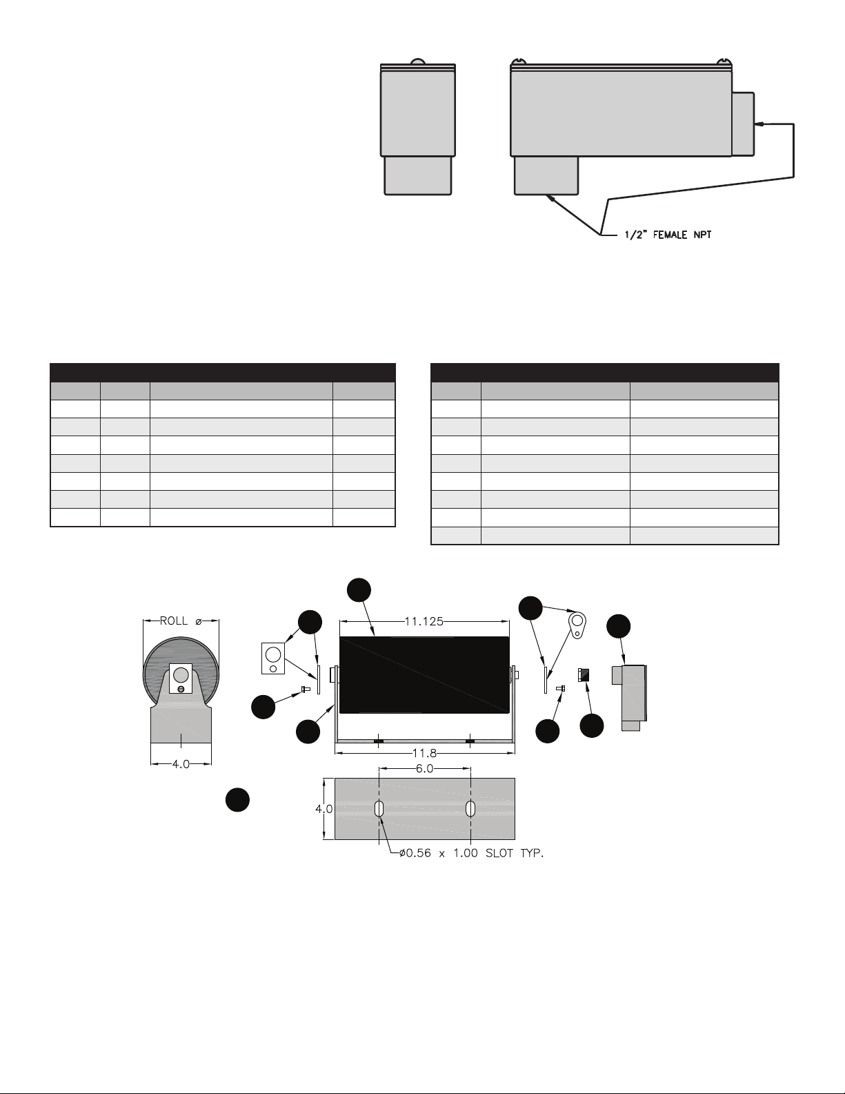
• The Universal Mount frame has two 0.56” x 1” slots for attaching the frame to the customer designed mounting location. Fasten the
Universal Mount frame in place using two ½” diameter bolts, lock washers, and nuts (not provided with the Universal Mount Smart
Roll). This mounting location must keep the Smart Roll in constant contact with the conveyor belt to provide accurate information.
• Place the Smart Roll in the Universal Mount frame and lock in place with the end clips and screws.
UNIVERSAL MOUNT SMART ROLL WIRING
• Disconnect and lockout power before starting wiring procedure.
The Smart Roll is provided with a ½ inch 90° elbow conduit access port. The Smart Roll cable is 2 wire, 22 AWG, PVC jacket, PVC
insulation, and 6 feet in length. No set-up is required to the sensor inside the Smart Roll. It is factory set and maintenance free.
DO NOT apply voltage directly across the wires of the Smart Roll Sensor, permanent damage may result. The Smart Roll is designed to be
used with a Smart Monitor, PLC or similar device.
DO NOT use an incandescent light bulb as a load. An overload will occur due to extremely high cold current.
DO NOT operate without a load. A dead short will result which may cause irreparable damage.
DO NOT directly operate a motor with the sensor. Always use a relay or other appropriate device.
• At this point a 2 wire cable needs to be routed from the control box housing the Smart Monitor to the Smart Roll. It is recommended
to use minimum of 22 AWG shielded cable. Shielded cable eliminates electromagnetic interference (EMI). It is advisable to route the
wires/conduit for the Smart Roll away from electrical power conduit as the electrical power may cause electromagnetic interference
(EMI) in the signal from the Smart Roll. If EMI is present the signal from the Smart Roll may not make it to the Smart Monitor or PLC.
This will result in the Smart Monitor or PLC getting faulty readings.
Conduit from the control box to the Smart Roll offers more protection to the cable. Any nick, gouge or cut in the cable wiring could
prevent the sensor signal from reaching the Smart Monitor.
PPI is not capable of being aware of all site and industry electrical requirements for an application, and cannot be held liable for
non-compliant installations. The product has been designed to be capable of meeting many requirements, and a qualified individual should
review the connection plan prior to installation. Connection of conduit to 90° elbow conduit access port does not meet intrinsically safe
requirements.
DO NOT PULL THE WIRES CONNECTED TO THE SMART ROLL. Pulling wire from inside the roll will cause damage and void warranty. Be
sure to protect the wire near elbow threads and all corners, as this may damage the wire/insulation.
• Remove the cover from the 90° elbow conduit access port and route the Smart Roll wires and the wires from the control box through
the conduit opening in the 90° elbow access port and out the rectangular opening.
• Attach the conduit to the 90° elbow access port.
A. UNIVERSAL MOUNT SMART ROLL
18
• Attach the Smart Roll wires to the wires from the control
box. Cut wires to proper length to fit in junction box. DO
NOT apply power to the sensor at this time. The Smart
Monitor or PLC provides the power for the Smart Roll.
To avoid damage, verify the circuit meets the sensor
specifications shown in section A4 prior to applying
power:
• Reinstall junction box lid and tighten screws to secure.
• Proceed to Section 4: Wiring the Smart Monitor.
UNIVERSAL MOUNT SMART ROLL DIAGRAM & PARTS
LIST:
2
3
4
1
5
8
7
6
4
FIGURE 3.1: 90° Elbow Conduit Access Port.
ASSEMBLY COMPONENTS
ITEM QTY DESCRIPTION PART #
1 1 Smart Roll TABLE
2 1 Universal Mount Frame 38040
3 1 D End Clip 47117
4 2 #12-3/8” Self Tapping Screw 31880
5 1 B End Clip 31800
6 1 Hex Bushing 34461
7 1 90º Elbow Conduit Access Port 34452
UNIVERSAL MOUNT SMART ROLLS
ROLL Ø ASSEMBLY PART # ROLL ONLY PART #
5.0 SAD5UMSB – 1P SAD5TE30SB – 1P
5.0 SAD5UMSB – 2P SAD5TE30SB – 2P
5.0 SAD5UMSB – 6P SAD5TE30SB – 6P
6.0 SAD6UMSB – 1P SAD6TE30SB – 1P
6.0 SAD6UMSB – 2P SAD6TE30SB – 2P
6.0 SAD6UMSB – 6P SAD6TE30SB – 6P
5.5 SAD5UMSB – 2PL4 SAD5TE30SB – 2PL4
6.5 SAD5UMSB – 2PL4 SAD6TE30SB – 2PL4

19
TROUGHING SMART ROLL MOUNTING INSTRUCTIONS:
Attention must be given to the location of the Smart Roll so that it is always in contact with the belt. Failure to mount properly may void
warranty and could cause damage to conveyor belt and other components.
NOTE: Care must be taken to avoid scraped, pinched, or crushed wiring. Wires that are scraped, pinched, or crushed during shipping,
handling or installation will void the warranty.
1. Identify the Smart Roll as a Troughing Smart Roll and select the mounting site on the conveyor. The Troughing Smart Roll is
designed to be placed in the wing roll position of a PPI CEMA C or D 20°, 35°, or 45° Equal Roll troughing frame.
2. Determine which side of the conveyor is desirable for running the conduit/wires for the Smart Roll. It is advisable to route the wires/
conduit for the Smart Roll away from electrical power conduit as the electrical power may cause electromagnetic interference (EMI) in
the signal from the Smart Roll. If EMI is present the signal from the Smart Roll may not make it to the Smart Monitor or PLC. This will
result in the Smart Monitor or PLC getting faulty readings.
3. Remove the wing roll from the troughing idler on the side the wires/conduit will be run. Keep the end clip, screw, and the center
clip.
4. Place the Smart Roll in the troughing idler with the wiring end in the end bracket and the non-wired end in the center bracket. Take
care that the wiring is not crushed. Ensure that the slots on the Smart Roll shaft are turned in the correct orientation to allow the
Smart Roll to drop fully into the brackets.
5. Replace the center clip in the center bracket.
6. Unscrew the hex bushing from the wired end of the Smart Roll and carefully slide it over the wiring and set aside to be replaced
later.
7. Slide the wires through the largest hole of the end clip and lock this end of the Smart Roll into the end bracket using the end clip
and the self-tapping screw.
8. Slide the hex bushing previously removed over the wiring and thread it onto the shaft.
TROUGHING SMART ROLL WIRING:
1. Disconnect and lockout power before starting wiring procedure.
The Smart Roll is provided with a ½ inch 90° elbow conduit access port. The Smart Roll cable is 2 wire, 22 AWG, PVC jacket, PVC
insulation, and 6 feet in length. No set-up is required to the sensor inside the Smart Roll. It is factory set and maintenance free.
DO NOT apply voltage directly across the wires of the Smart Roll Sensor, permanent damage may result. The Smart Roll is designed to
be used with a Smart Monitor, PLC or similar device.
DO NOT use an incandescent light bulb as a load. An overload will occur due to extremely high cold current.
DO NOT operate without a load. A dead short will result which may cause irreparable damage.
DO NOT directly operate a motor with the sensor. Always use a relay or other appropriate device.
2. At this point a 2 wire cable needs to be routed from the control box housing the Smart Monitor to the Smart Roll. It is recommended
to use minimum of 22 AWG shielded cable. Shielded cable eliminates electromagnetic interference (EMI). It is advisable to route the
wires/conduit for the Smart Roll away from electrical power conduit as the electrical power may cause electromagnetic interference
(EMI) in the signal from the Smart Roll. If EMI is present the signal from the Smart Roll may not make it to the Smart Monitor or
PLC. This will result in the Smart Monitor or PLC getting faulty readings.
Conduit from the control box to the Smart Roll offers more protection to the cable. Any nick, gouge or cut in the cable wiring could
prevent the sensor signal from reaching the Smart Monitor.
PPI is not capable of being aware of all site and industry electrical requirements for an application, and cannot be held liable for
non-compliant installations. The product has been designed to be capable of meeting many requirements, and a qualified individual
should review the connection plan prior to installation. Connection of conduit to 90° elbow conduit access port does not meet intrinsically
safe requirements.
DO NOT PULL THE WIRES CONNECTED TO THE SMART ROLL. Pulling wire from inside the roll will cause damage and void warranty. Be
A. TROUGHING SMART ROLL

20
sure to protect the wire near elbow threads and all corners,
as this may damage the wire/insulation.
3. Remove the cover from the 90° elbow conduit access
port and route the Smart Roll wires and the wires from
the control box through the conduit opening in the 90°
elbow access port and out the rectangular opening.
4. Attach the conduit to the 90° elbow access port.
5. Attach the Smart Roll wires to the wires from the control
box. Cut wires to proper length to fit in junction box. DO
NOT apply power to the sensor at this time. The Smart
Monitor or PLC provides the power for the Smart Roll.
To avoid damage, verify the circuit meets the sensor
specifications shown in section A4 prior to applying
power:
6. Reinstall junction box lid and tighten screws to secure.
7. Proceed to Section 4: “Wiring the Smart Monitor”.
FIGURE 3.1: 90° Elbow Conduit Access Port.
ASSEMBLY COMPONENTS
ITEM QTY DESCRIPTION PART #
1 1 Smart Roll TABLE
2 1 Hex Bushing 34461 Provided with Smart Roll
3 1 90º Elbow Conduit Access Port 34452 Provided with Smart Roll
4 1 20º Center Clip
35º Center Clip
45º Center Clip
00820
00835
00845
Not provided with Smart Roll.
Use existing Center Clip or
order required part number.
5 1
B End Clip
31800 Not provided with Smart Roll.
Use existing End Clip or order
part number 31800.
6 1
#12–3/8” Screw
31880 Not provided with Smart Roll.
Use existing Screw or order
part number 31880.
This manual suits for next models
1
Table of contents
Other PPI Industrial Equipment manuals


Popular Industrial Equipment manuals by other brands

ITEM
ITEM Table Column Set 2 E HD ESD 230V installation guide

Lukas
Lukas LX-Strut Translation of the original instructions

Afag
Afag PEL20 Assembly and operating instructions

CM
CM BEAM CLAMP operating instructions

Imperial
Imperial 1-1/8 OD Instructions of use

SNC
SNC LYTE LYNX P30112 Description & Installation


Siemens
Siemens POWER CONTROL Series Operation manual

Global
Global WF 1767-70 Series Instruction & parts manual

Kval
Kval 990FX Operation manual

Schrempp electronic
Schrempp electronic MG-3-T4-TRIO IOL M8 manual

Innotech
Innotech INNOTECH BEF 401-10 Instructions for installation and use

SUHNER MACHINING
SUHNER MACHINING BEM 6 Technical document