Adveco TOTEM T10 User manual
PRODUCT MANUAL
TR400061.r1
TOTEM T10, T20, T25
Cogeneration (CHP) Range
EXPERTLY ENGINEERED FOR YOU
Updated UK Maintenance Requirements
INCLUDING SERVICE LOG FOR SITE PERSONNEL & BUILDING CONTROLLERS
SEE PAGE 3 FOR
CRITICAL INFORMATION

Contact Details
2
TOTEM 10 - TOTEM 20 - TOTEM 25 - On-site Maintenance Procedures
Maintenance Guide Overview .........................................
.
...
.
..............
... 4
A. Purposes of this Guide ................................................................ 4
B. Symbols Used in this Guide ......................................................... 4
C. Safety Instructions ..................................................................... 5
Procedure Overview .............................................................................7
Getting to know the TOTEM CHP..........................................................11
Interrogating and Communicating with the CHP..................................... 13
Dealing with Lamps on the Front Panel.................................................14
Fault Codes.................................................................................
....... 16
Procedure 1: Resetting Alarms and Rebooting.......................................18
Procedure 2: External Checks .............................................................. 21
Prcoedure 3: Checking Water Flow .......................................................22
Procedure 4: Internal Checks............................................................... 23
Procedure 5: Checking Coolant Level.....................................
.
.............
.
24
Procedure 6: Checking Oil Level...........................................................
.
25
Procedure 7: Cleaning Water Strainer...................................................
.
26
Procedure 8: Checking Gas Supply.......................................................
.
27
Procedure 9: Cleaning Gas Sniffer........................................................
.
28
Procedure 10: Tightening Oil Filters......................................................29
Adveco Ltd
Unit 7 Armstrong Mall,Southwood Business Park
Farnborough Hampshire GU14 0NR
Contents
Procedure 0: Checking System Operational Characteristics.................
.
...17
Addendum to the User Guide and Maintenance Reuirements.
.
................. 3
T10 Maintenance Checks by Run Hours...................................................8
T20 Maintenance Checks by Run Hours...................................................9
T25 Maintenance Checks by Run Hours..................................................10
Service Log Book................................................................................30
CO Detector Calibration Book...............................................................32

EXPERTLY ENGINEERED FOR YOU
3
TOTEM 10 - TOTEM 20 - TOTEM 25 - On-site Maintenance Procedures
Addendum to the USER guide and Maintenance
Requirements of the TOTEM CHP
Valid as of 20 May 2021
A risk of the exhaust manifold assembly cracking has been identified on the Totem CHP. The cause
and pattern of the fault has been investigated, a risk management plan has been prepared and the
Health and Safety Executive has been informed. The HSE has carried out their own investigation and
has agreed the following plan sufficiently manages the risk.
The added measures for the User/ Building Controller are:
• To ensure the maintenance is always carried out on time and in line with manufacturer’s
instructions
• To check the unit weekly by logging in to determine if the maintenance visit is imminent and
booking it in with a service provider to be done on time
• To turn off the unit at the point the service interval is reached if the maintenance cannot be
carried out at that time.
• To review the number of starts against the run hours and if the ratio is under 2 hours/start to
review the design with the BMS company/ Adveco / designer
• Ensure the service provider follows the manufacturer’s instructions on the maintenance
regime, and particularly, that they change the exhaust manifold each service and follow the
maintenance requirements and test the CO detector.
• Arrange for training by Adveco on how to fulfil your Totem CHP maintenance requirements.
This is free.
The requirement to service a CHP system is vitally important, not only for reliability and longevity, but
also for safety. Machinery can become unsafe if not serviced regularly and ensuring regular and
correct maintenance is carried out to ensure safety is the responsibility of the building controller. If
the control measures are followed we are pleased to confirm that building occupants will not be at
risk from leakage of carbon monoxide from defects in the Totem CHP exhaust system.
These instructions may be updated from time to time and it is therefore important to regularly check
for updated information at www.adveco.co/CHPmaintenance/

[Danger] This symbol indicates operating procedures whose incorrect performance can cause injury or even
death.
[Warning] This symbol indicates operating procedures whose incorrect performance can seriously damage the
equipment.
[Information] This symbol indicates important information related to the use of the equipment.
Maintenance Guide Overview
A. Purposes of this Guide
It is the responsibility of the Building Controller to ensure the maintenance is carried out at the
correct interval by a suitably qualified service provider. This is to ensure the equipment continues
to operate in a safe and reliable manner. This document is designed to inform the building controller
of their responsibilities to ensure this work is completed correctly. Further information should be
gained from the Totem installation manual and the Totem user manual. A copy of the Totem
Service manual should be available for the service provider.
This document is also designed to be used be on-site or maintenance personnel to perform basic
maintenance and diagnostic procedures on the TOTEM CHP appliance. It includes an introduction to
the appliance, the interrogator, TOTEM fault codes and suggested resolutions.
All procedures are categorised into three tiers based on the skills, complexity, and risk involved:
Basic: All operators. Procedures at this level require no specialist skills or knowledge, and do not
involve any disassembly of or mechanical work on the appliance.
Intermediate: Operatives with relevant maintenance training and/or experience. Procedures at this
level include basic internal checks within the appliance.
Advanced: Operatives with relevant professional qualifications (gassafe) and experience.
Procedures at this level include works to the appliance gas supply and internal components.
Finally, this document includes the maintenance tasks to be carried out by the service provider on
pages 8-10. This document is in addition to the Totem manual and includes additional tasks
considered specific to the UK. This document must be shown to the service provider. This
information may change over time so at each visit it is necessary to refer to the website
www.adveco.co/CHPmaintenance/ to see if they have been updated.
B. Symbols Used in the Guide
4
TOTEM 10 - TOTEM 20 - TOTEM 25 - On-site Maintenance Procedures

If you smell gas odor:
turn your gas supply valve off;
ventilate the room;
do not operate any electrical device or appliance, including cell phones; leave the premises and call a
qualified technician or the gas utility company immediately from a different location. If they are
unavailable or in case of an emergency, call the local Fire Brigade;
if the room is equipped with a gas leak detection system, please report any possible malfunctioning of said
active safety equipment.
EXPERTLY ENGINEERED FOR YOU
5
TOTEM 10 - TOTEM 20 - TOTEM 25 - On-site Maintenance Procedures
If you see water, glycol, oil, or other fluids’ spills on the floor or near the Totem Unit:
turn the unit off;
call a qualified technician;
shut off the User system’s circuits, if any, e.g. water or gas supply
If you smell products of combustion:
turn the appliance off;
ventilate the room;
call a qualified technician;
if the room is equipped with a smoke/carbon monoxide detection system, please report any possible
malfunctioning of said active safety equipment.
C. Safety Instructions
Please refer to the TOTEM User Manual for a comprehensive list of safety instructions and potential
hazards associated with working on or in the vicinity of the TOTEM CHP appliance.
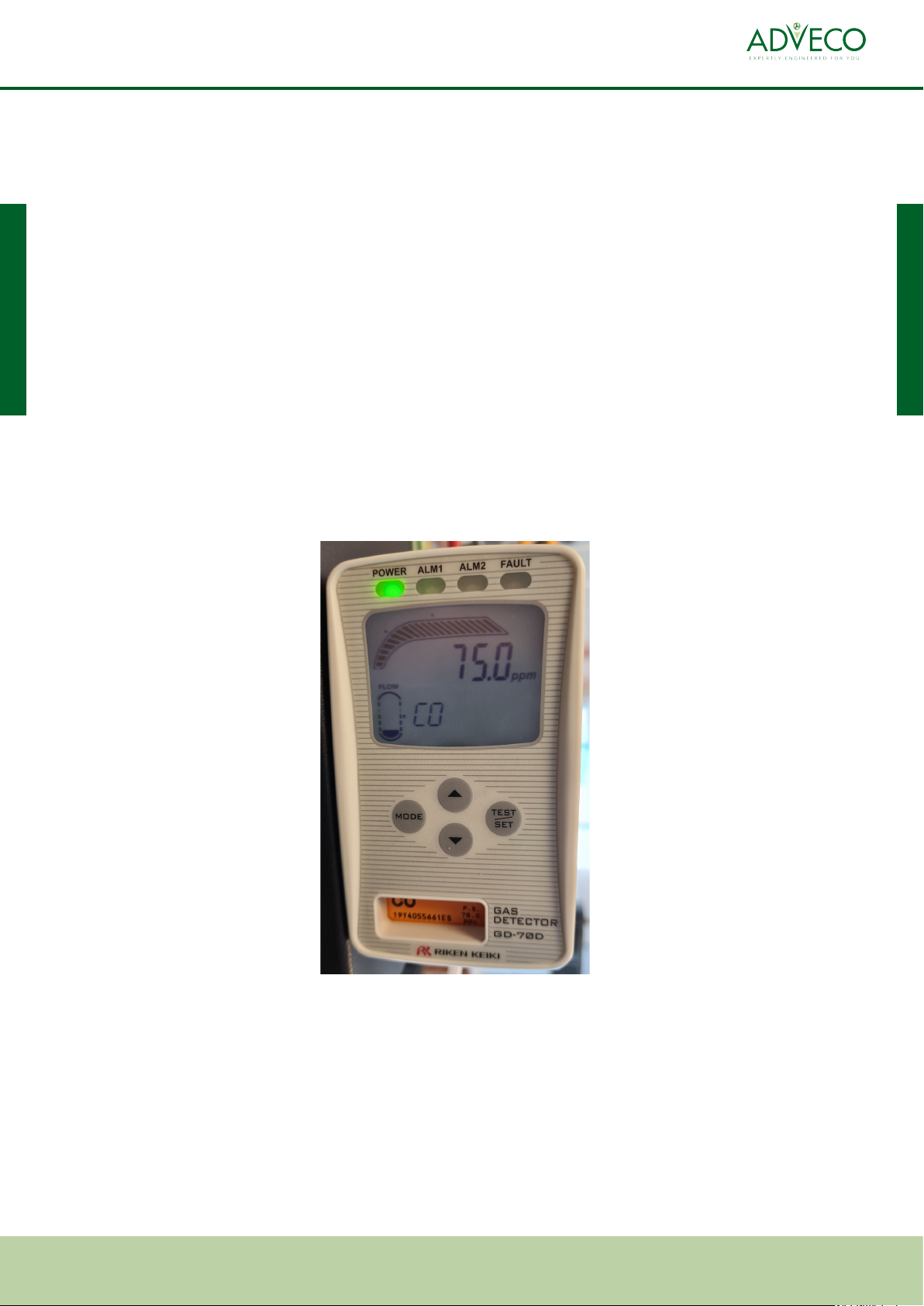
This TOTEM CHP unit has been fitted with an aftermarket CO detector to monitor the warm air
leaving the unit. It is unlikely that the CO detector will go off, however if it does:
•It will shut off the CHP unit
•It will not make a sound, but pressing the blue button on the CHP unit will not reset the CHP - the CO
detector will hold it off.
•It is likely that the CO has come form the CHP unit, but it is possible that it has come from another
appliance in the room, so proceed with caution.
•Do not try and reset the CO detector.
•The CO detector will shut off the TOTEM before the level is unsafe. Once the CHP is off, see if the CO level
reduces. This could take 15 minutes. If it does not reduce, or if it increases, turn off all other gas
appliances and exit the building.
•Call out your service provider.

Installation, calibration and modification of the gas feed system must be performed by a qualified
technician abiding by all applicable national and local standards as well as by the instructions provided in this
Guide.
Installation, calibration or modification of the electrical system must be performed by a qualified
technician abiding by all applicable national and local standards as well as by the instructions provided in this
Guide.
Installation, calibration or modification of the water system must be performed by a qualified technician abiding
by all applicable national and local standards as well as by the instructions provided in this Guide.
It is mandatory to connect the exhaust gas evacuation line of the appliance to an exhaust gas evacuation duct
built in compliance with all applicable legal requirements in force in the place where the TOTEM® unit is
installed. Failure to comply with said rule poses a serious risk to human and animal safety.
According to the provisions for use, the user has an obligation to keep the installed unit in good condition
and to ensure the safe and reliable functioning of the micro cogenerator and of all systems connected thereto,
having the relevant activities performed by qualified technicians.
Before switching the unit on, always ensure that all protective panels and guards have been properly mounted to
avoid risks to the safety of personnel.
Do not obstruct, not even partially, the suction duct and exhaust pipe ends.
Do not use or store any hazardous materials, such as explosive, combustible or flammable materials in the same
room where the micro cogenerator is installed.
When the unit is in operation, do not stay in the room where the unit is installed.
The micro cogenerator, any auxiliary components thereof, the systems needed for its functioning (GAS, water,
power, shut-off devices, firefighting equipment, detectors, panels, switchboards, components of the Totem
Unit’s equipment room etc.) must not be tampered with, modified or otherwise altered for any reason
whatsoever. Failure to comply with this provision may cause injuries or may damage, including severely, people,
animals or things.
6
TOTEM 10 - TOTEM 20 - TOTEM 25 - On-site Maintenance Procedures
Procedure Basic Intermediate Advanced
1 Resetting Alarms Resetting Alarms Resetting Alarms
2 External visual & audible
checks
External visual & audible
checks
External visual & audible
checks
3 Checking system water flow Checking system water
flow
Checking system water flow
4 Internal visual & audible
checks
Internal visual & audible
checks
5 Checking coolant level &
topping up
Checking coolant level &
topping up
6 Checking oil level Checking oil level
7 Cleaning water strainer Cleaning water strainer
8 Checking gas supply
9 Cleaning gas sniffer
10 Tightening oil filters
0 Checking system
operational parameters
Site Maintenance Items Required Quantity
Engine Oil 4 litres
Coolant Additive 1 litre
Demineralized Water 5 litre
Air Brush Can 1
Microfibre Cloths 10
7
EXPERTLY ENGINEERED FOR YOU
TOTEM 10 - TOTEM 20 - TOTEM 25 - On-site Maintenance Procedures
Procedure Overview
Checking system
operational parameters
Checking system
operational parameters
Weekly requirements of the building controller:
1. External visual and audible checks
2. Complete log book entry of system operational characteristics, including:
a. Water system flow rate
b. Check and note run hours and starts. Calculate the number of run hours per start and make sure it is
a minimum of 2 hours per start.
c. Check total run hours and compare them to the service interval. Book in a service visit if within 500
hours of the interval.
d. If the interval is about to be exceeded, the machine must be switched off until it has been serviced.
Yearly requirements of the building controller:
•Ensure that the manuals are available on site for the maintenance company
•Ensure a service provider is selected with the correct non-domestic gas safe accreditations including Direct
Gas Fired Engines
•Ensure the service report reflects that the requirements set out within this document have been carried out.
The service manual for the CO detector can be found at www.adveco.co/CHPmaintenance
Maintenance Basic Intermediate Advanced
Weekly 2 2 2
Monthly 3 3 3
4 4
5 5
6 6
Maintenance tasks need to be broken into
weekly checks by 'basic' level staff, and
should be the responsibility of the building
controller. Monthly checks should be by
on-site staff if qualified, or qualified off-site
staff.

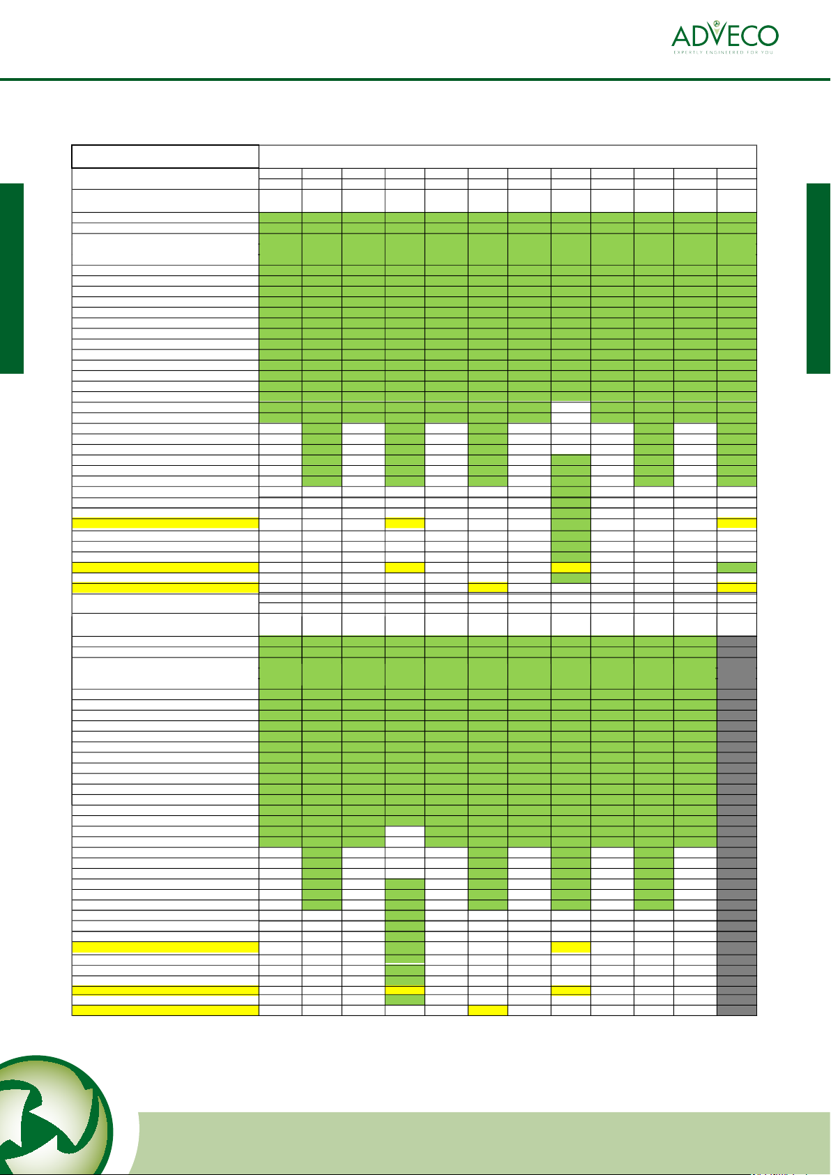
TOTEM 10
3000 6000 9000 12000 15000 18000 21000 24000 27000 30000
±5% ±5% ±5% ±5% ±5% ±5% ±5% ±5% ±5% ±5%
Maintenance Items T1A T1A T2 T1A T1A T2 T1A T1A T2 T3
General inspection of the unit XXXXXXXXXX
Check torque on fasteners and hoses XXXXXXXXXX
Check the tightness of all electrical connections XXXXXXXXXX
Check engine coolant level XXXXXXXXXX
Check gas leak sensor XXXXXXXXXX
Replace engine oil / refill tank XXXXXXXXXX
Replace oil filters XXXXXXXXXX
Replace primary air filter XXXXXXXXXX
Check valve clearances and adjust if necessary XXXXXXXXX
Replace spark plugs X X X
Replace cylinder head X X X
Replace spark plug cables X X X
Replace timing belt and tensioner X X X
Replace engine coolant X X X X
Replace Lambda probe (pre-cat) X X X X
Replace secondary air filter X X X X
Replace Lambda probe (post-cat) X
Clean exhaust gas heat exchanger (flue gas side) X
Clean exhaust gas heat exchanger (water side) X
Replace catalytic converter X
Replace engine X
Replace battery X
Replace gas actuator X
Replace Flexible Tubes of engine cooling system X X
Replace heat shield insulation panels X
Revamp generator
33000 36000 39000 42000 45000 48000 51000 54000 57000 60000
±5% ±5% ±5% ±5% ±5% ±5% ±5% ±5% ±5% ±5%
Maintenance Items T1A T2 T1A T1A T2 T1A T1A T2 T1A Overhaul
General inspection of the unit XXXXXXXXX
Check torque on fasteners and hoses XXXXXXXXX
Check the tightness of all electrical connections XXXXXXXXX
Check engine coolant level XXXXXXXXX
Check gas leak sensor XXXXXXXXX
Replace engine oil / refill tank XXXXXXXXX
Replace oil filters XXXXXXXXX
Replace primary air filter XXXXXXXXX
Check valve clearances and adjust if necessary XXXXXXXXX
Replace spark plugs X X X
Replace cylinder head X X X
Replace spark plug cables X X X
Replace timing belt and tensioner X X X
Replace engine coolant X X X
Replace Lambda probe (pre-cat) X X X
Replace secondary air filter X X X
Replace Lambda probe (post-cat)
Clean exhaust gas heat exchanger (flue gas side)
Clean exhaust gas heat exchanger (water side)
Replace catalytic converter
Replace engine
Replace battery
Replace gas actuator
Replace Flexible Tubes of engine cooling system X X
Replace heat shield insulation panels
Revamp generator
SCHEDULED SERVICE PLAN 0 - 60.000 h
Unit Running Hours
Unit Running Hours
Leak check around all flue joints for CO/CO2
Check all traps full of water
Check service log is being filled in, review start/stop ratio
Check for CO leakage around all exhaust joints
Calibrate and service CO detector
Check back pressure on flue from appliance test point
XXXXXXXXXX
XXXXXXXXXX
XXXXXXXXXX
XXXXXXXXXX
XXXXXXXXXX
XXXXXXXXXX
XXXXXXXXXX
Leak check around all flue joints for CO/CO2
Check all traps full of water
Check service log is being filled in, review start/stop ratio
Check for CO leakage around all exhaust joints
Calibrate and service CO detector
Check back pressure on flue from appliance test point
XXXXXXXXX
XXXXXXXXX
XXXXXXXXX
XXXXXXXXX
XXXXXXXXX
XXXXXXXXX
XXXXXXXXX
Check flue is bracketed properly and vibration
downstream of flex is minimal
Check flue is bracketed properly and vibration
downstream of flex is minimal
Check and replace gas hose every 5 years
8
TOTEM 10 - TOTEM 20 - TOTEM 25 - On-site Maintenance Procedures
T10 Maintenance Checks by Run Hours
TOTEM 20
2500 5000 7500 10000 12500 15000 17500 20000 22500 25000 27500 30000
±5% ±5% ±5% ±5% ±5% ±5% ±5% ±5% ±5% ±5% ±5% ±5%
Maintenance Items T1B T2 T1B T2 T1B T2 T1B T3 T1B T2 T1B T2
General inspection of the unit XXXXXXXXXXXX
Check torque on fasteners and hoses XXXXXXXXXXXX
Check the tightness of all electrical connections XXXXXXXXXXXX
Check engine coolant level XXXXXXXXXXXX
Check gas leak sensor XXXXXXXXXXXX
Replace engine oil / refill tank XXXXXXXXXXXX
Replace oil filters XXXXXXXXXXXX
Replace primary air filter XXXXXXXXXXXX
Check valve clearances and adjust if necessary XXXXXXX XXXX
Replace spark plugs XXXXXXX XXXX
Replace cylinder head XXX XX
Replace spark plug cables XXX XX
Replace timing belt and tensioner XXX XX
Replace engine coolant XXXXXX
Replace Lambda probe (pre-cat) XXXXXX
Replace secondary air filter XXXXXX
Replace Lambda probe (post-cat) X
Clean exhaust gas heat exchanger (flue gas side) X
Clean exhaust gas heat exchanger (water side) X
Replace catalytic converter XXX
Replace engine X
Replace battery X
Replace gas actuator X
Replace Flexible Tubes of engine cooling system XXX
Replace heat shield insulation panels X
Revamp generator X X
32500 35000 37500 40000 42500 45000 47500 50000 52500 55000 57500 60000
±5% ±5% ±5% ±5% ±5% ±5% ±5% ±5% ±5% ±5% ±5% ±5%
Maintenance Items T1B T2 T1B T3 T1B T2 T1B T2 T1B T2 T1B Overhaul
General inspection of the unit XXXXXXXXXXX
Check torque on fasteners and hoses XXXXXXXXXXX
Check the tightness of all electrical connections XXXXXXXXXXX
Check engine coolant level XXXXXXXXXXX
Check gas leak sensor XXXXXXXXXXX
Replace engine oil / refill tank XXXXXXXXXXX
Replace oil filters XXXXXXXXXXX
Replace primary air filter XXXXXXXXXXX
Check valve clearances and adjust if necessary XXX XXXXXXX
Replace spark plugs XXX XXXXXXX
Replace cylinder head X X X X
Replace spark plug cables X X X X
Replace timing belt and tensioner X X X X
Replace engine coolant XXXXX
Replace Lambda probe (pre-cat) XXXXX
Replace secondary air filter XXXXX
Replace Lambda probe (post-cat) X
Clean exhaust gas heat exchanger (flue gas side) X
Clean exhaust gas heat exchanger (water side) X
Replace catalytic converter X X
Replace engine X
Replace battery X
Replace gas actuator X
Replace Flexible Tubes of engine cooling system X X
Replace heat shield insulation panels X
Revamp generator X
SCHEDULED SERVICE PLAN 0 - 60.000 h
Unit Running Hours
Unit Running Hours
Change old style exhaust manifold
Calibrate and service CO detector
Check back pressure on flue from appliance test point
Leak check around all flue joints for CO/CO2
Check all traps full of water
Check service log is being filled in, review start/stop ratio
Check for CO leakage around all exhaust joints
Check flue is bracketed properly and vibration
downstream of flex is minimal
XXXXXXXXXXXX
XXXXXXXXXXXX
XXXXXXXXXXXX
XXXXXXXXXXXX
XXXXXXXXXXXX
XXXXXXXXXXXX
XXXXXXXXXXXX
XXXXXXXXXXXX
Change old style exhaust manifold
Calibrate and service CO detector
Check back pressure on flue from appliance test point
Leak check around all flue joints for CO/CO2
Check all traps full of water
Check service log is being filled in, review start/stop ratio
Check for CO leakage around all exhaust joints
Check flue is bracketed properly and vibration
downstream of flex is minimal
XXXXXXXXXXX
XXXXXXXXXXX
XXXXXXXXXXX
XXXXXXXXXXX
XXXXXXXXXXX
XXXXXXXXXXX
XXXXXXXXXXX
XXXXXXXXXXX
EXPERTLY ENGINEERED FOR YOU
9
TOTEM 10 - TOTEM 20 - TOTEM 25 - On-site Maintenance Procedures
T20 Maintenance Checks by Run Hours
Check and replace flexible gas hose every 5 years

TOTEM 25
2500 5000 7500 10000 12500 15000 17500 20000 22500 25000 27500 30000
±5% ±5% ±5% ±5% ±5% ±5% ±5% ±5% ±5% ±5% ±5% ±5%
Maintenance Items T1b T2 T1b T2 T1b T3 T1b T2 T1b T2 T1b T3
General inspection of the unit X X X X X X X X X X X X
Check torque on fasteners and hoses X X X X X X X X X X X X
Check the tightness of all electrical connections X X X X X X X X X X X X
Check engine coolant level X X X X X X X X X X X X
Check gas leak sensor X X X X X X X X X X X X
Replace engine oil / refill tank X X X X X X X X X X X X
Replace oil filters X X X X X X X X X X X X
Replace primary air filter X X X X X X X X X X X X
Check valve clearances and adjust if necessary X X X X X X X X X X
Replace spark plugs X X X X X X X X X X
Replace cylinder head X X X X
Replace spark plug cables X X X X
Replace timing belt and tensioner X X X X
Replace engine coolant X X X X X X
Replace Lambda probe (pre-cat) X X X X X X
Replace secondary air filter X X X X X X
Replace Lambda probe (post-cat) X X
Clean exhaust gas heat exchanger (flue gas side) X X
Clean exhaust gas heat exchanger (water side) X X
Replace catalytic converter X X X
Replace engine X X
Replace battery X X
Replace gas actuator XX
Replace Flexible Tubes of engine cooling system X X X
Replace heat shield insulation panels X X
Revamp generator X X
32500 35000 37500 40000 42500 45000 47500 50000 52500 55000 57500 60000
±5% ±5% ±5% ±5% ±5% ±5% ±5% ±5% ±5% ±5% ±5% ±5%
Maintenance Items T1b T2 T1b T2 T1b T3 T1b T2 T1b T2 T1b Overhaul
General inspection of the unit X X X X X X X X X X X
Check torque on fasteners and hoses X X X X X X X X X X X
Check the tightness of all electrical connections X X X X X X X X X X X
Check engine coolant level X X X X X X X X X X X
Check gas leak sensor X X X X X X X X X X X
Replace engine oil / refill tank X X X X X X X X X X X
Replace oil filters X X X X X X X X X X X
Replace primary air filter X X X X X X X X X X X
Check valve clearances and adjust if necessary X X X X X X X X X X
Replace spark plugs X X X X X X X X X X
Replace cylinder head X X X X
Replace spark plug cables X X X X
Replace timing belt and tensioner X X X X
Replace engine coolant X X X X X
Replace Lambda probe (pre-cat) X X X X X
Replace secondary air filter X X X X X
Replace Lambda probe (post-cat) X
Clean exhaust gas heat exchanger (flue gas side) X
Clean exhaust gas heat exchanger (water side) X
Replace catalytic converter X X
Replace engine X
Replace battery X
Replace gas actuator X
Replace Flexible Tubes of engine cooling system X X
Replace heat shield insulation panels X
Revamp generator X
SCHEDULED SERVICE PLAN 0 - 60.000 h
Unit Running Hours
Unit Running Hours
Change old style exhaust manifold
Calibrate and service CO detector
Check back pressure on flue from appliance test point
Leak check around all flue joints for CO/CO2
Check all traps full of water
Check service log is being filled in, review start/stop ratio
Check for CO leakage around all exhaust joints
X X X X X X X X X X X
X X X X X X X X X X X
X X X X X X X X X X X
X X X X X X X X X X X
X X X X X X X X X X X
X X X X X X X X X X X
X X X X X X X X X X X
X X X X X X X X X X X
X X X X X X X X X X X
X X X X X X X X X X X
X X X X X X X X X X X
X X X X X X X X X X X
X X X X X X X X X X X
X X X X X X X X X X X
X X X X X X X X X X X
X
X
X
X
X
X
X
X X X X X X X X X X X X
Change old style exhaust manifold
Calibrate and service CO detector
Check back pressure on flue from appliance test point
Leak check around all flue joints for CO/CO2
Check all traps full of water
Check service log is being filled in, review start/stop ratio
Check for CO leakage around all exhaust joints
Check flue is bracketed properly and vibration
downstream of flex is minimal
Check flue is bracketed properly and vibration
downstream of flex is minimal
Check and replace flexible gas hose every 5 years
10
TOTEM 10 - TOTEM 20 - TOTEM 25 - On-site Maintenance Procedures
T25 Maintenance Checks by Run Hours

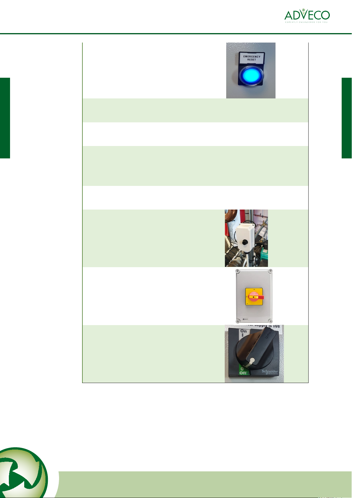
Machine Isolator: Electrical isolator to cut power supply to the unit. Required safe isolation for
servicing and access into the panel. This isolator should isolate all power to the unit, however all
installations are different. Look for labels that indicate multiple live supplies exist within the panel
and if present isolation is necessary at multiple points. Regardless, after gaining access the control
panel should be tested with suitable test equipment to ensure it is safely isolated.
Rotary Isolator: Minimum level of electrical isolation necessary to gain access inside the control panel.
When in the off position the panel can be opened, but there is still live 415V/3phase electricity in the
machine up to the isolator. Not a sufficient level of safe electrical isolation for servicing, this must be
done through the machine isolator. Only trained technicians should access the panel with only the
rotary isolator in the off position.
Informational
(Alarm) Lamp
Rotary Isolator
Grid Connect
Indicator Lamp
Power Indicator
Lamp
Emergency Stop
Button
Reset Button/
Lockout (Alarm)
Lamp
On/Off Switch
Machine Isolator
(adjacent to
machine)
Right hand side
Left hand side
Front
Getting to Know the TOTEM CHP
EXPERTLY ENGINEERED FOR YOU
11
TOTEM 10 - TOTEM 20 - TOTEM 25 - On-site Maintenance Procedures
Informational (Alarm) Lamp: Lamp on indicates the machine is communicating. Could indicate non
critical information, self resetting temporary blocking alarm, lockout that can be reset remotely, or
lockout that must be manually reset on site.
Grid Connect Lamp: Lamp on indicates the machine is generating electricity
Power Indicator Lamp: Lamp on indicates the power is on to the unit
Emergency Stop Button: Press in case of emergency to shut unit off
Reset Button/Lockout (Alarm) Lamp: Lamp on indicates a lockout alarm that must be reset by
pressing the blue button
On/Off Switch: Used to turn off machine to prevent operation, while still leaving the main power on
to keep the battery charged. Should normally be set to On.
CO Detector
12
TOTEM 10 - TOTEM 20 - TOTEM 25 - On-site Maintenance Procedures

The human/machine interface (HMI) of the Totem CHP is a smartphone or tablet via the Totems
wifi hotspot in the following way:
Once connected press the menu button in the top left corner and select the section that is required.
Interrogating and Communicating with the TOTEM CHP
EXPERTLY ENGINEERED FOR YOU
13
TOTEM 10 - TOTEM 20 - TOTEM 25 - On-site Maintenance Procedures

Typically there is no reason to connect and interrogate the machine unless user data is required
such as current temperatures, run hours, time until servicing, etc.
There are combinations of illuminated lamps that may require the user to connect and interrogate.
1. Power on lamp illuminated, all other lamps off, Machine NOT running.
a. The machine NOT running is NOT a fault, the machine will run often, but not all the
time. The arrangement explained above is likely to be a healthy condition where the
unit is simply in standby because the system is up to temperature, the system was up
to temperature and now the machine is in ‘anti-cycling’ mode, or the machine does
not have an external run/enable signal. It could also indicate a fault combined with a
faulty lamp.
b. It is recommended that if this is the condition of the unit that nothing is done and it
is checked again 2 hours later. Most conditions that cause this standby arrangement
will clear in 2 hours and the unit will reset.
c. Connect to the unit and check the following in order:
i. Alarms, Check for active alarms
1. If there is an active alarm note it and follow the procedure for that
alarm.
ii. Configurations, Totem Shutdown/Restart temperature
iii. Real time data, Totem Inlet water temperature
1. When the Totem Inlet water temperature reaches the shutdown
temperature the machine will stop. It will restart when the Totem
inlet water temperature drops to the restart temperature. If the
Totem Inlet water temperature is above the restart temperature it
should degrade over time and the machine will restart. Check it
again in a few hours. If the temperature is still high it could indicate
a pump failure or BMS control problem.
iv. Real time data, Engine Inlet water temperature
1. The anti-cycling algorhithm will prevent the machine from restarting
until the engine inlet temperature drops below a setpoint fixed by
machine type, which could be as low as 50C. If the Engine inlet water
temperature is above 50C then recheck in 2 hours and it should have
restarted.
v. Real time data, Logical State of Totem
1. Waiting conditions for engine to start indicates that there is no
enable/run signal from the controls or BMS. Investigate through the
BMS.
Dealing with the Lamps on the Front of the TOTEM CHP
14
TOTEM 10 - TOTEM 20 - TOTEM 25 - On-site Maintenance Procedures

ii. The machine may have an active alarm that has stopped the unit from
operating, which will automatically reset after a period of time or when the
fault is removed
iii. The machine may have an active alarm that will not automatically reset and
needs to be reset either remotely through the Cloud based monitoring
system or locally by following the reset procedure (Procedure 1)
b. As both conditions in i. and ii. will either reset or not stop the machine from
operating it is recommended that nothing is done immediately and it is checked
again 2 hours later. Most conditions that cause this i. and ii. will clear in 2 hours and
the unit will run.
c. Connect to the unit and check the following:
i. Alarms, Check for active alarms
1. If there is an active alarm note it and follow the procedure for that
alarm.
3. Reset button/ Lockout alarm lamp illuminated, Machine NOT running.
a. This is a lockout alarm. It can only be reset on site by following procedure 1.
2. Power on and Informational (Alarm) Lamps illuminated, Reset button/ Lockout alarm
lamp not illuminated, Machine running or not.
a. This arrangement could be the cause of three conditions.
i. The machine may be healthy (running or in standby) but there is information
being communicated that indicates a part is worn, a service is imminent, or a
sensor is out of calibration. These informational faults do not stop the
machine from operating and will be cleared/rectified during the next service.
EXPERTLY ENGINEERED FOR YOU
15
TOTEM 10 - TOTEM 20 - TOTEM 25 - On-site Maintenance Procedures

Fault Codes Description Advice/Cause Procedure Basic Intermediate Advanced
5a01 Emergency knock off
button activated
Ascertain
why/who pressed
it before resetting
1 x x x
5a02 Lockout alarm Power cut/safety
chain/high
voltage
1 x x x
5b02, 5b06 QF1 Circuit breaker trip 1 x x
5c01—5c07 Reboot request 1 x x x
5d01,5d02 Enable/run signal not
present
Check the BMS
system
n/a x x x
5e01, 5e02 Grid/current/voltage
imbalance
If recurring
contact Adveco
1 x x x
5e11 – 5e23 Various
voltage/amperage grid
issues
Refer to Adveco
for info
n/a
5428,5401,542d,
5501,5408,540d
Engine/Coolant/
building flow
temperature too high
Building flow too
low
3,7 3 only x x
5432,5412,5413 Temperature in
machine housing
Check plantroom
temperature
2 x x x
5418,541d,541e,
5422
Related to exhaust
temperature
Refer to Adveco n/a
5502 Related to coolant level 4,5 x x x
5601—5604 Related to CHP Oil level 4,6,10 x x x
5f01 – 5f03,
5f06 – 5f11
Related to fuel/air mix
or Lambda
sensors/catalytic
converter
If recurring
contact Adveco
1 x x x
5f04 Incoming gas pressure
low
8 x
5f05 Gas detector activated 9 x
0560 Battery voltage too low Replace battery n/a x x x
5406,5407,5409,
540b, 540c,540e,
5410,5411,5414,
5416,5417,5419,
541b,541c,541f,
5420,5421,5423,
5426,5427,5429,
542b,542c,542e,
5430,5431
Non critical
informational code
regarding sensor
calibration
Inform Adveco
when booking in
service visit
n/a
0300—0304,
1000—1004
Non critical
informational code
indicating that a service
may be imminent
Inform Adveco
when booking
service & if
frequency
increase
n/a
All other alarms Procedure 1 and report to Adveco if
persistent
1 x x x
16
TOTEM 10 - TOTEM 20 - TOTEM 25 - On-site Maintenance Procedures

Procedure 0Checking System Operational Characteristics
Connect to the machine with a smartphone or tablet as described in
Interrogating and Communicating with the Totem CHP.
Read down the page to find "Number of Engine Starts" to record the total
number of CHP starts.
Find "Hours of Operation on Network" to record the total run hours of
the unit.
Divide the run hours by the number of starts to calculate the average number
of hours run per start.
Refer to the service logbook on the next page of this document and fill in
the above information for the current week.
Use the previous week log book information to calculate the number of
hours run and starts during the last week, and the number of hours since
the last service.
T10 units require servicing every 3000 hours
T20 and T25 units require servicing every 2500 hours
Book a service visit if the unit is within 500 hours of requiring a service.
On the online dashboard, use the menu in the top left of the screen
to navigate to "Real Time Data"
EXPERTLY ENGINEERED FOR YOU
17
TOTEM 10 - TOTEM 20 - TOTEM 25 - On-site Maintenance Procedures
1
2
3
4
5
6

Procedure 1
Resetting Alarms / Rebooting
1
Connect to the machine with a smartphone or tablet as described in
Interrogating and Communicating with the Totem CHP, go to alarms, and note
the active alarm.
1.1
If the alarm was 5a01, ascertain the
reason someone pressed the emergency
knock off button, then if is safe to do so
turn the button clockwise to reset it (it
must be fully out.)
2
Press the Reset (BLUE) button and hold
for 2 seconds
2.1
The blue lamp should go out and the machine should start within 5 minutes. If
the unit restarts no further action is required.
2.2
If the lamp stays off, but it does not start, refer to ‘dealing with lamps’ page to
interrogate why it has not started.
2.3
If the lamp does not go out, or if it comes back on immediately or comes on
when the machine attempts to operate then go on to section 3.
3
If the unit tried to start, connect to the machine, check and note the alarm code
again
3.1
Turn off the CHP using the rotary isolator
on the control panel and wait 30
seconds.
2
Turn on the CHP using the rotary isolator on the control panel.
3
The internal fan will start and the Reset button/ lockout (alarm) button will
illuminate
4
Wait for up to 5 minutes.
18
TOTEM 10 - TOTEM 20 - TOTEM 25 - On-site Maintenance Procedures
5
Press the Reset (BLUE) button and hold
for 2 seconds
5.1
The blue lamp should go out and the machine should start within 5 minutes. If
the unit restarts no further action is required.
5.2
If the lamp stays off, but it does not start, refer to ‘dealing with lamps’ page to
interrogate why it has not started.
5.3
If the lamp does not go out, or if it comes back on immediately or comes on
when the machine attempts to operate, and the alarm code is 5a02, 5b02 or
5b06 then go to section 6. For all other alarms contact Adveco and give them
the alarm code.
6
The following checks for 5a02, 5b02, and 5b06 are for intermediate technical
level users
6.1
(5a02 only) Locate the overheat stat in
the flow pipework outside of the
machine and press the button under
the cap. If it clicks go back to section 2.
If it does not click continue to 6.2
6.2
Isolate the machine with the Machine
Isolator adjacent to the machine
6.3
Turn off the CHP using the rotary isolator
on the control panel
EXPERTLY ENGINEERED FOR YOU
19
TOTEM 10 - TOTEM 20 - TOTEM 25 - On-site Maintenance Procedures

6.4
Open the door using the key provided
6.5
5b02,5b06:
Touching nothing else, locate the rotary
circuit breaker (red circle) and turn the
black dial anticlockwise to 9:00, then turn
it clockwise to 12:00.
5a02:
Locate the multimeter (green circle) and
note down the displayed voltage.
6.6
Close and lock the control panel door, turn the machine on at the Machine
Isolator and the Rotary Isolator
6.7
The internal fan will start and the Reset button/ lockout (alarm) button will
illuminate
6.8
Wait for up to 5 minutes
6.9
Press the Reset (BLUE) button and hold
for 2 seconds
The blue lamp should go out and the machine should start within 5 minutes. If
the unit restarts no further action is required.
If the machine does not successfully run then contact Adveco with the alarm
codes and the voltage reading (if 5a02)
20
TOTEM 10 - TOTEM 20 - TOTEM 25 - On-site Maintenance Procedures
This manual suits for next models
2
Table of contents
Other Adveco Industrial Equipment manuals


