Steris Basil 1000 User manual

OPERATOR MANUAL
Basil® 1000
Feeder Bottle Filler
(2004-03-04) P122994-772


i
Table of Contents Operator Manual 122994-772
A WORD FROM STERIS CORPORATION
This manual contains important information on proper use and maintenance
of the Basil®1000 Feeder Bottle Filler. All personnel involved in the use and
maintenance of this equipment must carefully review and comply with
the warnings, cautions, and instructions contained in this manual. These
instructions are important to protect the health and safety of personnel
operating this equipment and should be retained in a conveniently accessible
area for quick reference.
Complete instructions for uncrating and connecting utilities, as well as
equipment drawings, have been furnished. If missing, contact STERIS for
replacement copies, giving the unit serial and model numbers.
STERIS carries a complete line of accessories for use with this equipment. A
STERIS representative will gladly review these with you.
A listing of the
Safety Precautions
to be observed when operating and
servicing this equipment can be found in Section 1 of this manual. Do not
operate or service the equipment until you have become familiar with this
information.
Any alteration of this equipment not authorized or performed by STERIS which
could affect units operation will void the warranty, could violate federal, state
and local regulations, and could jeopardize your insurance coverage.
The Basil 1000 Feeder Bottle Filler is a manifold-type filler designed for filling
basket loads of feeder bottles used in the care of laboratory animals.
A thorough preventive maintenance program is essential to safe and proper
unit operation. This manual contains maintenance schedules and procedures
which should be followed for satisfactory equipment performance.
You are encouraged to contact STERIS concerning extended service main-
tenance agreements to give your unit planned maintenance, assuring equip-
ment performance according to factory specifications. A global network of
skilled service specialists can provide periodic inspections and adjustments
to assure low-cost peak performance. STERIS can provide information
regarding annual maintenance agreements.
See inside back cover for contact information.
Indications for Use
Service Information
Advisory
©2004, STERIS Corporation. All rights reserved. Printed in Canada

ii
122994-772 Operator Manual Table of Contents
THIS PAGE INTENTIONALLY LEFT BLANK

iii
Table of Contents Operator Manual 122994-772
TABLE OF CONTENTS
Section Title Page
A WORD FROM STERIS CORPORATION ................................................... i
1 LISTING OF SAFETY PRECAUTIONS AND SYMBOLS ..................... 1-1
2 UNCRATING/INSTALLATION INSTRUCTIONS ................................. 2-1
2.1 Uncrating Instructions ............................................................................................. 2-1
2.1.1 Open Crate ....................................................................................................... 2-1
2.1.2 Move Unit and Remove Skid ............................................................................ 2-1
2.1.3 Prepare Unit for Installation............................................................................... 2-1
2.2 Installation Instructions ............................................................................................ 2-3
2.2.1 Before Installing Equipment .............................................................................. 2-3
2.2.2 Technical Specifications ................................................................................... 2-3
2.2.3 Install Anchorage System ................................................................................. 2-4
2.2.4 Connect Utilities ................................................................................................ 2-4
2.2.5 Cleanup ............................................................................................................ 2-4
2.3 Installation Checklist ................................................................................................ 2-5
3 COMPONENT IDENTIFICATION ....................................................... 3-1
3.1 Component Identification ........................................................................................ 3-1
3.2 Controls ................................................................................................................... 3-1
3.3 Accessories ............................................................................................................. 3-2
3.3.1 Filler Header ..................................................................................................... 3-2
3.3.2 Bottle Baskets................................................................................................... 3-3
4 OPERATING INSTRUCTIONS ........................................................... 4-1
4.1 Before Operating Equipment ....................................................................................... 4-1
4.2 Filling the Bottles.......................................................................................................... 4-1
5 ROUTINE MAINTENANCE ................................................................ 5-1
5.1 General ........................................................................................................................ 5-1
5.2 Daily Cleaning.............................................................................................................. 5-2
5.3 Weekly Cleaning .......................................................................................................... 5-2
6 TROUBLESHOOTING ....................................................................... 6-1
7 REPLACEMENT PARTS AND PRODUCTS ........................................ 7-1

iv
122994-772 Operator Manual Table of Contents
THIS PAGE INTENTIONALLY LEFT BLANK

1-1
Listing of Safety Precautions and Symbols OperatorManual 122994-772
The following list of
Safety Precautions
must be observed when operating and servicing this equipment. WARNINGS
indicate the potential for danger to personnel, and CAUTIONS indicate the potential for damage to equipment. These
Safety Precautions
are repeated, where applicable, throughout the manual.
WARNING – PERSONAL INJURY AND/OR EQUIPMENT DAMAGE HAZARD:
Only fully qualified service personnel should assemble and/or make adjustments to this equipment. Assembly
or adjustments done by inexperienced, unqualified personnel could cause personal injury or result in costly
damage.
Regularly scheduled preventive maintenance, in addition to the faithful performance of the minor maintenance
described within this manual, is required for safe and reliable operation of this equipment. Contact STERIS to
schedule preventive maintenance.
When moving the unit, use a forklift.
WARNING – ELECTRIC SHOCK AND/OR BURN HAZARD:
Disconnect all utilities to equipment before servicing. Do not service the equipment unless all utilities have been
properly locked out. Always follow electrical safety-related work practice standards.
Disconnect main power switch before opening cover and working on electrical components.
For continued protection against fire hazard replace only with same type and rating of fuse.
WARNING – CHEMICAL BURN EYE AND/OR INJURY HAZARD:
Liquid descaler is corrosive and can cause adverse effects to exposed tissues. Do not get in eyes, on skin, or
attempt to swallow. Avoid breathing of mists. Read and follow the precautions and instructions on the Descaler
label and in the Material Safety Data Sheet (MSDS) prior to use.
Wear gloves and eye protection when using a descaling product. Avoid contact with eyes or skin. If spilled or
splashed, flush with plenty of water for 15 minutes. If swallowed, do NOT induce vomiting. Administer an alkali
with plenty of water. Seek medical attention immediately.
WARNING – LACERATION HAZARD:
When removing bolts, wear gloves to protect your hands.
WARNING – HEALTH HAZARD:
Vapors from solvent can be harmful. Use with adequate ventilation. Follow directions on the container.
WARNING – SLIPPING HAZARD:
To prevent slips, keep floors dry. Promptly clean up any spills or condensation.
LISTING OF SAFETY PRECAUTIONS AND
SYMBOLS 1
(See next page for cautions)
1-2
122994-772 OperatorManual Listing of Safety Precautions and Symbols
CAUTION – POSSIBLE EQUIPMENT DAMAGE:
Use non-abrasive cleaners when cleaning unit. Follow directions on containers and rub in a back and-forth motion
(in same direction as surface grain). Abrasive cleaners will damage stainless steel. Cleaners rubbed in a circular
motion or applied with a wire brush or steel wool can be harmful to stainless steel. When using Pry Cream, rub
in a back-and-forth motion (in same direction as surface grain). Do not rub with a rotary or circular motion.
When removing adhesives from stainless steel, use a slovent specially formulated for that purpose. Rub in a back-
and-forth motion (in same direction as surface grain). Solvent rubbed in a circular motion or applied with a wire
brush or steel wool on assembies can be harmful to stainless steel. Do not use solvents on painted surfaces.
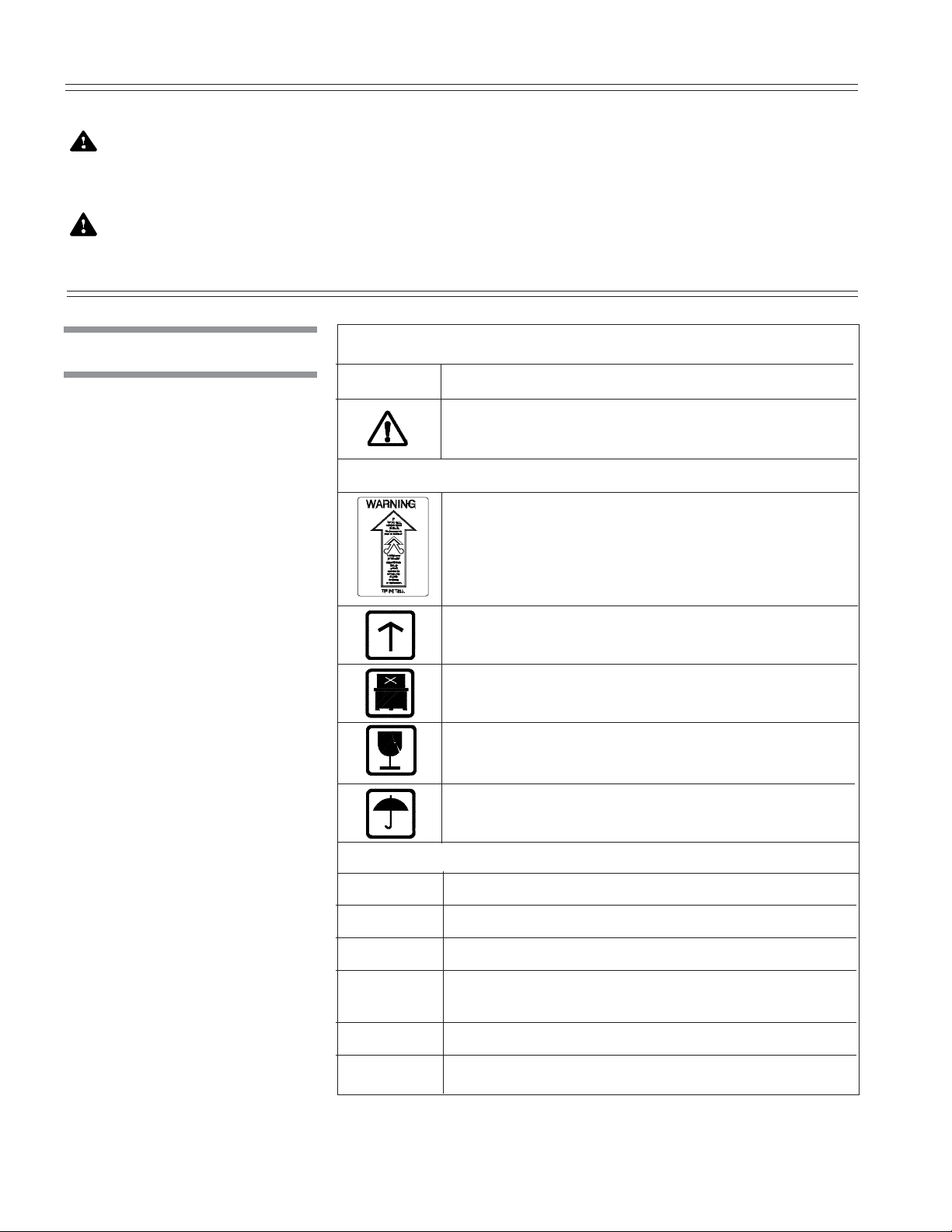
Symbols Symbols on the Unit:
Symbol Definition
Warning. Refer to Manual for Further
Information.
Symbols on the Crate:
TIP'N TELL Indicator.
"If TIP'N TELL arrow point is blue, this package has
been on its side or tipped over in transit. Make note on
bill of ladding and check for damage. Any claims for
tipping will be based on this notation."
This Side Up.
Do Not Stack.
Fragile.
Keep Dry.
Information on the Nameplate:
MOD. Model of the Unit.
SER. Serial Number of the Unit.
kV Power Rating of the Unit.
VVolt, Number of the Phase (Three or One [blank])
Alternating Current.
AAmperage Rating of the Unit.
PH/Hz Hertz – Frequency of the Unit.

2-1
Uncrating/Installation Instructions Operator Manual 122994-772
UNCRATING/INSTALLATION INSTRUCTIONS
A room layout, floor plan, and equipment drawing, showing all utility and space
requirements, were shipped with the unit. The clearance space, specified on
the floor plan, is necessary for proper installation, operation, and maintenance
of the unit. If any of these documents are missing or misplaced, contact
STERIS, giving the unit serial number and model numbers. Replacement
copies will be sent to you promptly.
NOTE: When uncrating unit, note the following:
1) Uncrate on a level floor, as close to installing site as possible.
2) Crate dimensions are: 51 x 32 x 68" (1295 x 812 x 1727 mm).
3) Crate maximum weight is 300 lb (136 kg). Use a forklift to move crates.
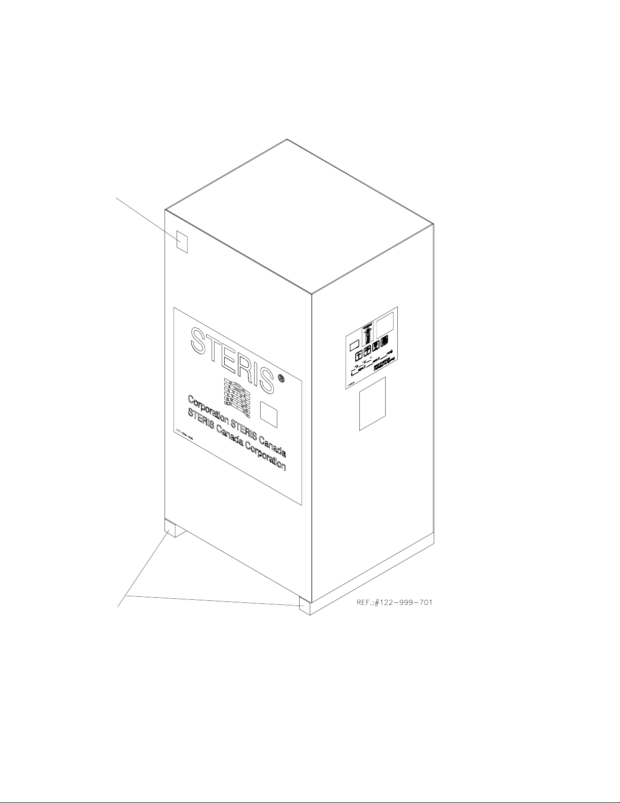
1. Verify Tip’N Tell indicator located outside crate (see Figure 2-1). Tip
indicator contains a blue compound at the bottom of the indicator. If unit has
been tipped, residue from the blue compound will be found higher up in the
indicator. If unit has been tipped, notify STERIS and arrange to have a
service technician review the equipment and determine if unit was dam-
aged.
2. Assure crate is positioned so it can be opened from the top. Provide a clear
work area on all sides.
3. Carefully cut and remove bands from crate. Discard bands before continu-
ing.
4. Using a nail puller, remove and discard top wooden panel.
5. Remove and discard side wooden panels.
6. Remove and discard polystyrene wrap from around unit.
1. With the unit still mounted on the skid, position forklift under unit frame and
move unit to installation site.
2. Unscrew and discard lag bolts holding anchorage brackets to skid.
3. Pull out and discard base.
1. Remove all tape and/or foam packing from Bottle Filler.
2. Remove tape securing drain cap to sump.
3. Slide Filler Header Manifold (accessory) into connection.
2
2.1 Uncrating
Instructions
WARNING – LACERATION
HAZARD: When removing
bolts, wear gloves to pro-
tect your hands.
2.1.1 Open Crate
2.1.2 Move Unit and
Remove Skid
WARNING – PERSONAL
INJURY AND/OR EQUIP-
MENT DAMAGE HAZARD:
When moving the unit, use
a forklift.
2.1.3 Prepare Unit for
Installation
2-2
122994-772 Operator Manual Uncrating/Installation Instructions
Figure 2-1. Crate
Tip Indicator
Skid
2-3
Uncrating/Installation Instructions Operator Manual 122994-772
1. Review the installation requirements:
a. Clearance - The clearance space shown on the equipment drawing
indicates the space necessary for easy installation and proper operation
and maintenance of the Basil® 1000 Feeder Bottle Filler.
b. Utility service lines:
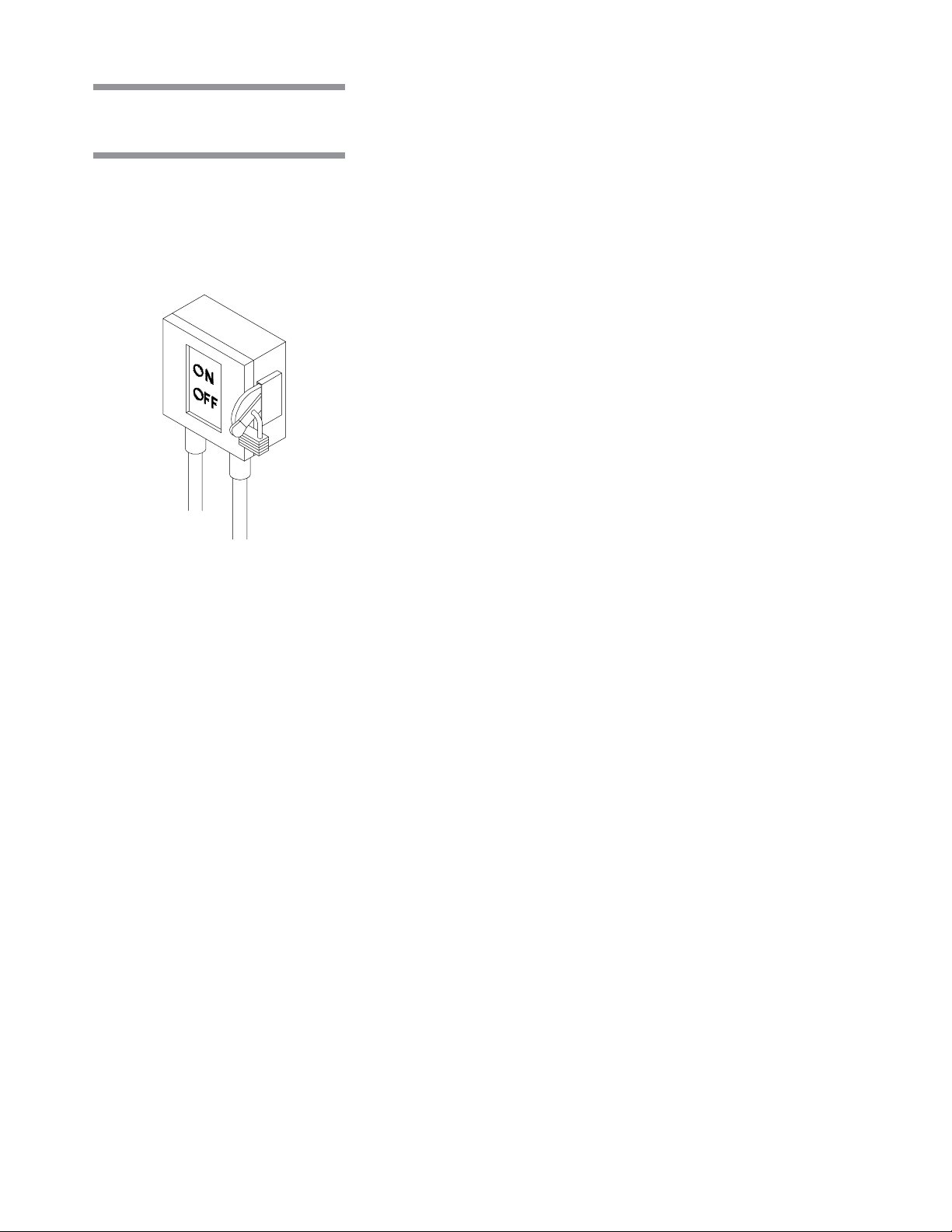
• Disconnect switch (not by STERIS) must be installed in the electric
supply line near the bottle filler (see Figure 2-2). Disconnect switch
must be capable of being locked in the OFF position only.
• If this machine is installed next to other equipment, disconnect switch
should be located so that service can be shut off to one piece of
equipment at a time.
• Utility service requirements are as shown on the equipment drawing.
Verify the equipment drawing or identification plate (located over
electrical box cover) for proper voltage.
2. Assure the unit is placed, as shown on equipment drawing, in correct
relation to building supply lines.
3. Verify that the bottle filler is level.
a. Place a spirit level end-to-end and side-to-side on top of filling area.
b. If necessary, level the unit end-to-end and side-to-side, by adjusting the
leveling legs.
4. Unit is installed on Non-slip floor surface.
These specifications are intended to describe the technical information given
on the nameplate of your unit and to state other relevant information. Verify
Equipment Drawing or nameplate, for proper voltage and amperage.
• Voltage, Amperage, and Power Consumption
The Basil 1000 Feeder Bottle Filler
operates on:
• 120 V~, 60 Hz, 1-phase, 2-wire
• Maximum current and power consumptions are:
• 120 V~, 1A, 0.12 kW
• Permissible Environmental Conditions
This equipment is designed to give optimal results in an indoor environment
where temperature is maintained between 41-104 °F (5-40 °C) and where
maximum relative humidity is 80% for temperatures up to 88 °F (1 °C) decreas-
ing linearly to 50% relative humidity at 104 °F (40 °C).
• Seismic Anchorage System
A Seismic Tie Down System is available for high risk seismic zones.
2.2 Installation
Instructions
2.2.1 Before Installing
Equipment
2.2.2 Technical
Specifications
Figure 2-2. Disconnect
Switch
2-4
122994-772 Operator Manual Uncrating/Installation Instructions
Once unit is level, install anchorage system as follows:
1. Mark floor holes position. (If anchoring brackets do not touch the floor use
shims.)
2. Using a forklift, move the unit to clear area.
3. Drill holes in floor.
4. Using a forklift, bring unit back into position.
5. Bolt brackets into position using bolts provided.
1. DRAIN - Connect building waste line to unit drain line.
2. COLD WATER - Connect cold water supply line from building to unit as
described in the Equipment Drawing.
3. ELECTRICITY - Connect building electrical supply line to unit electrical
supply box as described in the Equipment Drawing.
1. Remove any adhesive found on panels with a small amount of nonflam-
mable cleaning solvent. Keep solvents away from all painted surfaces or
damage may result.
2 Remove all protective paper from the unit cabinet panels. Slowly peel paper
away from stainless steel to reduce the level of static discharge.
3. Inspect filler head and filling area to assure all materials used during
installation have been removed.
THIS COMPLETES THE INSTALLATION.
Before operating equipment,
confirm that all items on installation checklist have been satisfactorily imple-
mented and operational test is conducted by a qualified service technician.
Follow procedure described in Section 4.2,
Filling the bottles
.
2.2.4 Connect Utilities
2.2.5 Cleanup
WARNING – HEALTH HAZ-
ARD: Vapors from solvent
can be harmful. Use with
adequate ventilation. Fol-
low directions on the con-
tainer.
CAUTION – POSSIBLE
EQUIPMENT DAMAGE:
When removing adhesives
from stainless steel, use a
solvent specially formu-
lated for that purpose. Rub
in a back-and-forth motion
(in same direction as sur-
face grain). Solvent rubbed
in a circular motion or ap-
plied with a wire brush or
steel wool on assemblies
can be harmful to stainless
steel. Do not use solvents
on painted surfaces.
2.2.3 Install Anchorage
System

2-5
Uncrating/Installation Instructions Operator Manual 122994-772
2.3 Installation
Checklist
After installing the unit, complete the following checklist to assure complete
and correct installation. Contact STERIS to schedule a demonstration of proper
equipment operation.
Shutoff valve (not provided by STERIS), for maintenance purposes, is
installed on the water line and is in compliance with local codes.
Disconnect switch, capable of being locked in OFF position only, is installed
on electrical supply line near the unit and in compliance with local codes.
NOTE: If unit is installed next to other equipment, shutoff valve and disconnect
switch should be located so that service can be shut off to one piece of
equipment at a time.
Feeder Bottle Filler is positioned, as shown on floor plan, with required
clearance space and in relation to building water supply line.
Feeder Bottle Filler is level. If necessary, use adjustable legs and/or add
shims (not included) to level unit.
Building waste line is connected to unit as specified on equipment drawing.
Non-slip floor surface (not provided by STERIS) installed around unit.

2-6
122994-772 Operator Manual Uncrating/Installation Instructions
THIS PAGE INTENTIONALLY LEFT BLANK
3-1
Component Identification Operator Manual 122994-772
3.1 Component
Identification
COMPONENT IDENTIFICATION
Become familiar with all component and control locations and functions before
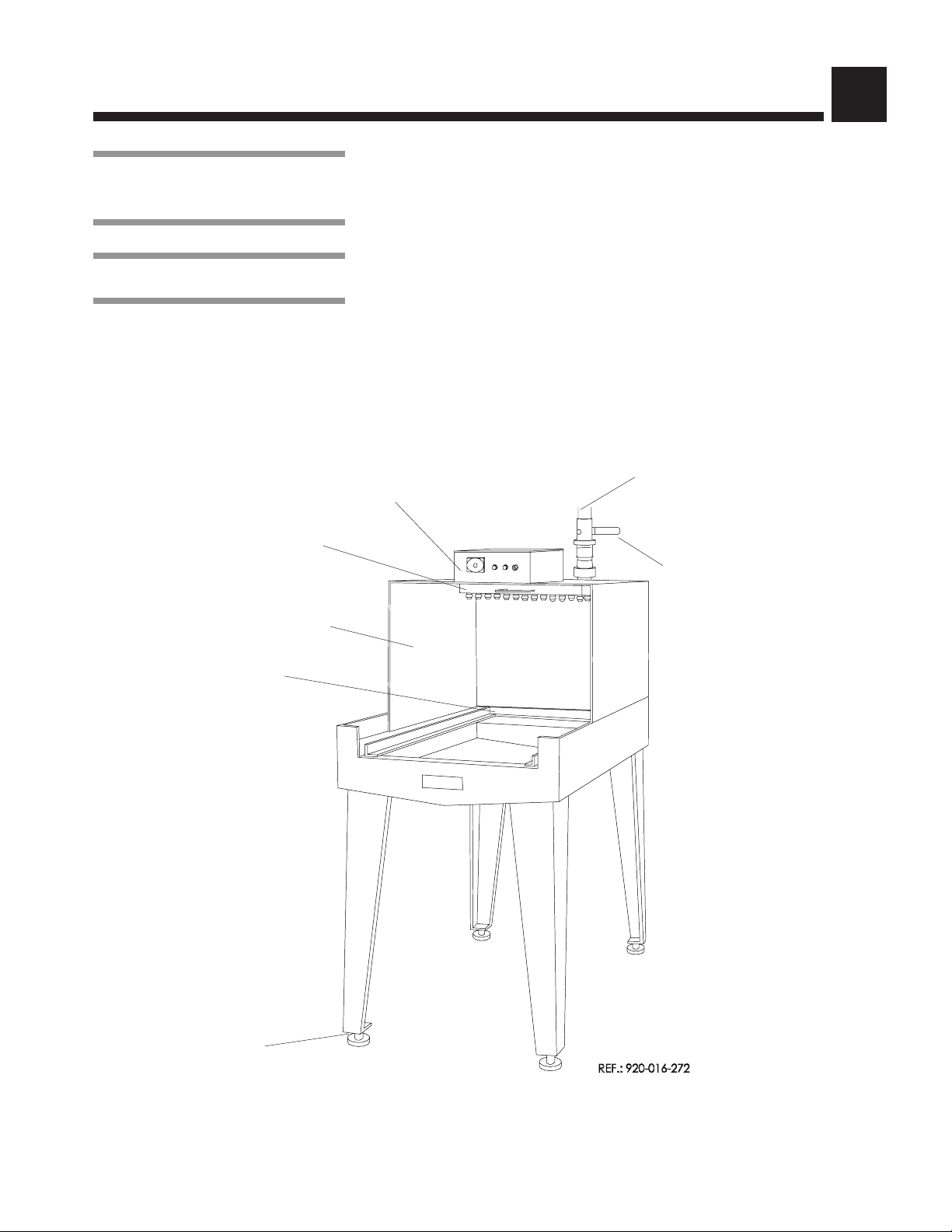
operating the Basil®Feeder Bottle Filler (see Figure 3-1).
See Figures 3-1 and 4-1.
Electrical control panel is composed of the following elements:
•Main Power ON/OFF selector switch;
•START-MAN Pushbutton - For manual operation, press and hold green
lighted pushbutton to obtain desired filling level for bottles;
•START-AUTO Pushbutton - For automatic operation, press blue lighted
pushbutton to activate timer;
•Timer - Set desired filling time to automatically fill the bottles.
3
Figure 3-1. Basil 1000 Feeder Bottle Filler
Adjustable Feet
Electrical Control Panel
Shutoff Valve
Filler Header with Jets
Water Line Connection
Splash Hood
Basket Stop
3.2 Controls
3-2
122994-772 Operator Manual Component Identification
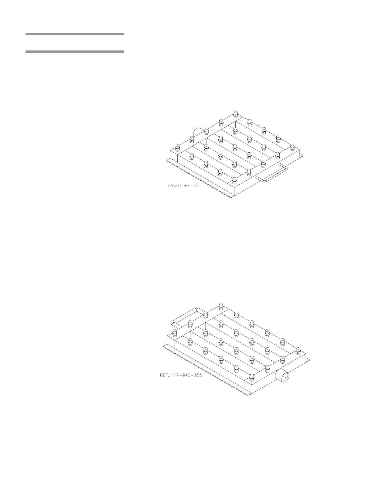
3.3 Accessories
Stainless-steel manifold headers can accommodate different bottle/basket
sizes. Each manifold has individual stainless-steel jets for each bottle. It
connects to Bottle Filler by a quick-disconnect clamp.
•5 x 5 Filler Header (Figure 3-2):
Dimensions: 14-3/4 x 16-3/4 x 2-3/4" (370 x 430 x 70 mm)
Coverage: 25 bottles
3.3.1 Filler Header
Figure 3-2. 5 x 5 Filler Header
Figure 3-3. 4 x 6 Filler Header
• 4 x 6 Filler Header (Figure 3-3):
Dimensions: 11-1/2 x 20-1/2 x 2-3/4" (290 x 520 x 70 mm)
Coverage: 24 bottles
3-3
Component Identification Operator Manual 122994-772
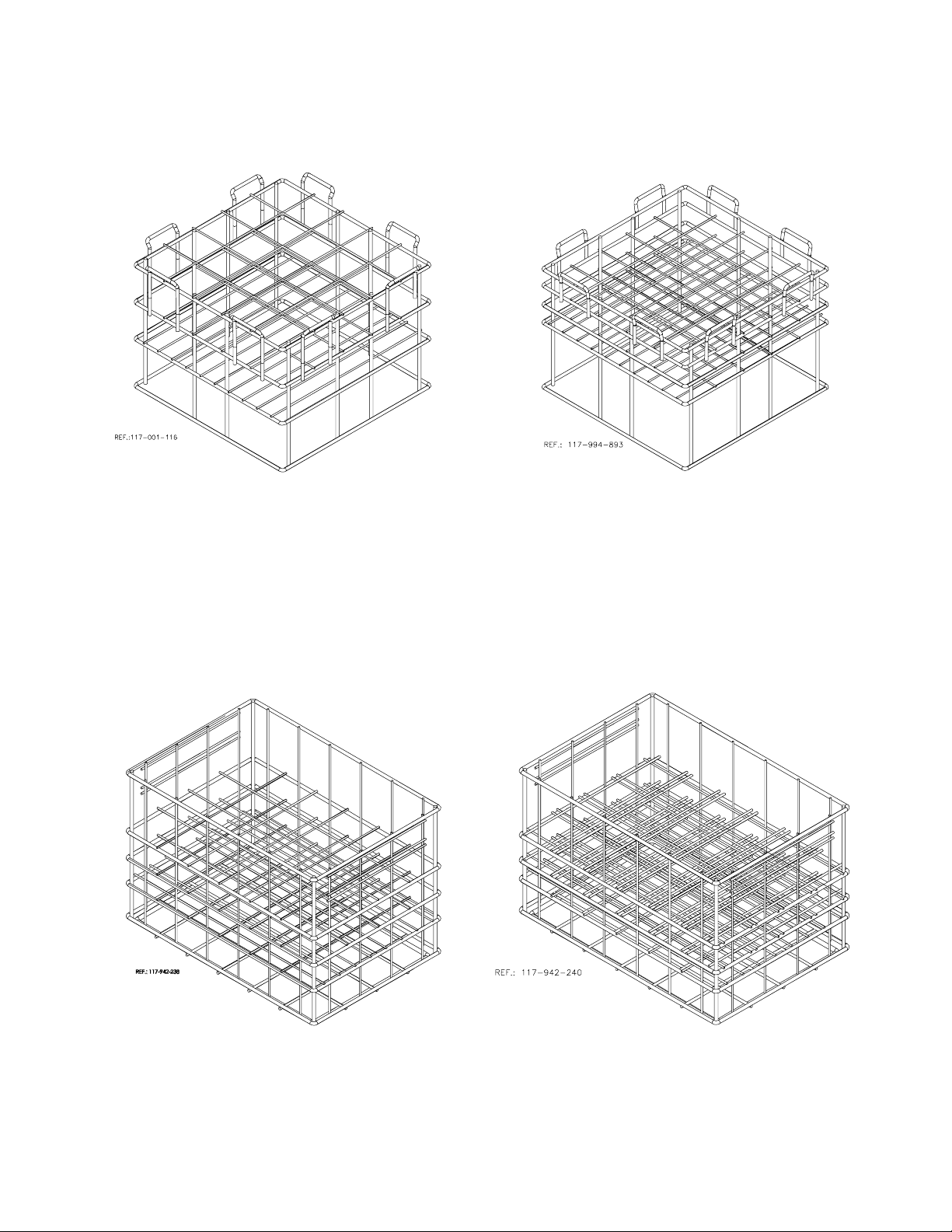
3.3.2 Bottle Baskets Stainless-steel bottle baskets can accommodate different bottle sizes. Refer
to Figures 3-4 through 3-7
Figure 3-4. 5 x 5 Bottle Basket
(16 oz bottles [454 mL])
Figure 3-6. 4 x 6 Bottle Basket
(16 oz bottles [454 mL])
Figure 3-5. 5 x 5 Bottle Basket
(8 oz bottles [227 mL])
Figure 3-7. 4 x 6 Bottle Basket
(8 oz bottles [227 mL])

3-4
122994-772 Operator Manual Component Identification
THIS PAGE INTENTIONALLY LEFT BLANK

4-1
Operating Instructions Operator Manual 122994-772
4.1 Before Operating
Equipment
OPERATING INSTRUCTIONS
NOTE: Refer to Section 3 for location of components.
Check that unit shutoff valve (water) is open.
See Figure 4-1
1. Place a basket of clean bottles under the filler header manifold up to the
basket stops.
2. Fill all bottles simultaneously as follows:
•Manual Operation
a. Turn Main Power ON/OFF selector switch to ON position.
b. Press and hold START-MAN button (green) until desired filling level for
bottles is reached. Release button
•Automatic Operation
a. Turn Main Power ON/OFF selector switch to ON position.
b. Set timer to desired filling time.
c. Press START-AUTO button (blue) to activate timer and start filling the
bottles. If the timer is set properly, it times out as bottles are filled.
NOTE: To set, turn the timer knob to the desired time necessary to fill bottles
(time may vary depending on size of bottles). A few trials with a basket in the
filling area may be necessary to determine the appropriate fill time.
d. Remove basket of filled bottles.
4
4.2 Filling the
Bottles
WARNING – SLIPPING
HAZARD: To prevent slips,
keep floors dry. Promptly
cleanup any spills or con-
densation.
Figure 4-1. Control Panel
Timer
Main Power ON/OFF
Selector Switch
(Red)
START-MAN Button
(Green)
START-AUTO Button
(Blue)

4-2
122994-772 Operator Manual Operating Instructions
THIS PAGE INTENTIONALLY LEFT BLANK
Table of contents


