STOKVIS ENERGY SYSTEMS SMART DISPLAY UNIT Operator's manual

Instruction Manual.
WARNINGS
1 This appliance must only be installed by a competent person in accordance with
the requirements of the Codes of Practice or the rules in force.
2 All external wiring MUST comply with the current IEE wiring regulations.
3 Warning this appliance must be earthed.
SMART DISPLAY UNIT
USER INSTRUCTION MANUAL
INDEX Section
Introduction ---------------------------------------------------------------------- 1
Display Access ------------------------------------------------------------------ 2
Parameter Settings ------------------------------------------------------------ 3
Additional Details --------------------------------------------------------------- 4

1.1 General.
The Smart Display Unit (SDU) enables the user
to view an d adjust sel ected controll er para me-
ters within the
controller. It pro-
vides all the fa-
cilities necessary
for the opera tion
of the Eco noair
Direct Gas F ired
Heater.
The SDU co nnects directl y to the micropro ces-
sor controller located in the Econoair unit.
1.2 Buttons
The requi red data can be sele cted o r changed
via 4 LED illuminated push buttons.
The display screen can be navigated b y press-
ing the & buttons whi ch will allow you to
navigate through the vario us screen pages. The
screen pages operate in a sequential continuous
loop.
The main headings are as follows:
1.3 Display
The SDU presents the information on a 4 row by
20-character backlit display. The backlight
automatically swit ches off 20 second s after the
last button is pre ssed but re-pressing any of the
buttons will re-activate.
There is a cursor on the scre en which should be
located beneath the first letter of the module o n
the page. If the cu rsor is located anywhere else
on the scree n pre ss the button until it is in the
position shown.
All the adju stments fro m the SDU can be PIN
protected u sing the controller’s built -in se curity
system.
1. Introduction.
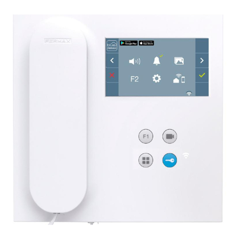
fig.1. SDU unit
fig.2. User buttons
fig.3. Home Page Display
ECONOAIR AHU
07/03/06 16:07
Sensor(s)
Knob(s)
Switch(s)Input(s)
Time Zones(s)
fig.4. Main heading sequence

2. Display Access.
2.1 Description
Pressing the & the b uttons
will navigate through the various
screen page s as this flow cha rt
example shows.
2.2 Parameters.
The follo wing screen pages
have pa rameters th at can be
changed via the display but-
tons:
Find the scre en page sho wing
the parameter that you wi sh to
change by pressin g the or
th buttons.
Pressing the button will
move the cu rser to the line of
the display you require.
Once the parameter h as been
modified, pressing the but-
ton will move the curser up to
the top line of the display.
The pa rameter ha s no w been
successfully changed.
2.3 PIN protection.
The SDU is sup plied with PIN
protection. If you attem pt to
change a parameter the display
will ask for a PIN number.
Enter the first numbe r of your
PIN using the and but-
tons then press to move the
curser to the next nu mber.
Once the last number has been
entered an d butto n is
pressed, the display will return
to the param eter that you were
attempting to adjust.
If the corre ct code ha s been
entered the parameter wi ll be
adjustable.
If the incorre ct code h as been
entered the display will ask you
to enter the PIN again.
The PIN entry display will time-
out 10 seconds after th e last
button press. The PIN itself will
remain ac tive for 2 minutes after
the last button is pre ssed after
which it will expire.
2.3.1 PIN entry.
etc.
YOUR PIN NUMBER IS SHOWN
ON THE LAST PAGE OF THIS
MANUAL
Sensor 1
Room Sensor
18.60 DegC
Sensor 2
Duct Sensor
38.96 DegC
Sensor 3
Outside Air Sensor
7.4 DegC
Knob 1
Occupied Setpoint
20.00 DegC
Knob 2
Non Occupied Setpoint
8.00 DegC
Knob
Switch
Time Zone
Knob 1
Occupied Setpoint
20.00 DegC
-
PIN? 5 ***
-
PIN? 6 ***
-
PIN? * 5 **
-
PIN? * 4**
-
PIN? ** 5 *

3. Parameter Settings.
3.2 Setting Time Clock
Find the Ti me Zone 1 scree n
page by pressing
Pressing will move the cursor
to the to the third line of the dis-
play.
Press the or buttons to tog-
gle and cho ose between every
days of the wee k an d ne xt days
of the week.
Pressing will move the cursor
to the to the fourth lin e of the
display.
Press the and buttons to
toggle a nd choose b etween the
three availa ble time zones for
every day. i.e. the unit can be
programmed to turn On a nd Off
three times within each day.
Pressing will move the cursor
to the On time.
Use the & buttons to
set the On time
Pressing will move the cursor
to the Off time.
Use the & buttons to
set the Off time
Once the On and Off time s have
been modified, pressing the th
button will move the curser up to
the top line of the di splay. The
On & Off times have now been
saved.
Knob 1
Occupied Set Point
19.00 DegC
Knob 1
Occupied Set Point
19.10 DegC
Knob 1
Occupied Set Point
19.10 DegC
Time Zone 1
Heating Times
Next Monday
On1 7:00 Off1 17:00
Time Zone 1
Heating Times
Next Monday
On2 7:00 Off2 17:00
Time Zone 1
Heating Times
Next Monday
On2 6:30 Off2 17:00
Time Zone 1
Heating Times
Next Monday
On2 6:30 Off2 17:00
Time Zone 1
Heating Times
Next Monday
On2 6:30 Off2 15:30
3.1 Room Setpoint
Find the O ccupied Set Poi nt dis-
play by pressing the or the th
buttons.
Pressing the button will move
the curser to the third line of the
display.
Use the & buttons
to set the On time
Once the temperature ha s been
modified, pressing the button
will move the curser up to the top
line of the display.
Example
Knob 1
Occupied Set Point
20.00 DegC
Knob 1
Occupied Set Point
20.00 DegC
Knob 1
Occupied Set Point
2
0.00 DegC
Knob 1
Occupied Set Point
20.00 DegC
Knob 1
Occupied Set Point
19.00 DegC
Time Zone 1
Heating Times
Every Monday
On1 7:00 Off1 17:00
Time Zone 1
Heating Times
Every Monday
On1 7:00 Off1 17:00
Time Zone 1
Heating Times
Next Monday
On1 7:00 Off1 17:00

3.3 Fault Indication
The Econ oair unit has inbuilt
safety features. If the unit
senses a fault the Red Fault
light above the display will
illuminate.
There are two standard faults:
• Lockout
• Overheat
The fault light can also be used
to indicate the other fa ults .
These fault indication s are not
standard and are only possible
if the custo mer ha s sp ecified
them. Some examples are:
• Filter Dirty
• Fan Trip
• Inverter Fault
To find the cause of the Fault
Light che ck the Status Page s
by pressing the button.
The Burn er Lockout Status
Page would appear as below.
The Overhe at Status Page
would appear as below.
3.3.1 Lockout reset
The Eco noair unit has Flame
Safe Guard Control s (FSGC)
fitted as sta ndard to comply with
the EN525 standard.
The FSGC will lockout t he unit
for the following reasons:
• Insufficient airflow
• Faulty flame detection
• Faulty gas valve solenoid
• Loss of flame
• Loss of airflow
If the unit se nses a fa ult the Red
Fault Light above the display will
illuminate.
Check the lockout statu s page to
make sure the unit is in a lockout
state. See diagram opposite.
The unit will cease to operate in
this state.
To reset the lockout find the lock-
out reset mode page by pressin g
the button.
Press to move cursor to line
three.
Press to bring up On.
Press and wait for 60 seconds
for the light to turn off and for the
unit to attempt to s tart up. If the
lockout light turns o n aga in you
will need to call the servi ce
d e p a r t m e n t f o r f u r t h e r
assistance.
Example
Switch 3
Lockout Reset
Off
Switch 3
Lockout Reset
Off
Time Zone 1
Heating Times
Every Monday
On1 7:30 Off1 17:00
Time Zone 1
Heating Times
Every Monday
On1 7:30 Off1 17:00
Time Zone 1
Heating Times
Every Monday
On1 7:30 Off1 15:00
Input 4
Burner Lockout
Off
Input 4
Burner Lockout
On
Input 5
Overheat
Off
Input 5
Overheat
On
Time Zone 1
Heating Times
Every Monday
On1 7:00 Off1 17:00
Time Zone 1
Heating Times
Every Monday
On1 7:00 Off1 17:00
Time Zone 1
Heating Times
Every Monday
On1 7:00 Off1 15:00
Time Zone 1
Heating Times
Every Monday
On1 7:00 Off1 17:00

4.0 Additional details
4.1 BST/GMT
Press and hold all four but tons
together.
Release buttons when the
screen flashes.
Find the IQ Time scree n page
by pressing the button.
4.2 PIN Number
USE PIN NO. 3232
Switch 3
Lockout Reset
On
Switch 3
Lockout Reset
On
3.3.2 Overheat Status
The Econoair Heater unit has an
overheat stat fitted as st andard
to c omply with the EN525 s tan-
dard.
If the temperature withi n the
Econoair unit incre ases b eyond
a factory se t safe temperatu re
limit, the unit will autom atically
cut the powe r to the controls of
the unit.
If the unit overhe ats the red fault
light above the displ ay will
illuminate.
Check the overheat statu s page
to make su re the unit is in an
overheat state. See diagram on
previous page.
The unit ca nnot be re set via the
controller.
Call a qualifi ed gas en gineer to
carry out a f ull inspe ction of the
unit.
IQ Time
± 00 Hours
00/00—00/00
10/12/04—15:34


DOC REF GB/NIC/015/0310
STOKVIS ENERGY SYSTEMS,
UNIT 34 CENTRAL PARK ESTATE,
34 CENTRAL AVENUE,
WEST MOLESEY,
SURREY KT8 2QZ
TEL: 0208 7833050
FAX: 0208 7933051
EMAIL: info@stokvisboilers.com
WEBSITE: www.stokvisboilers.com
Table of contents
