StoneAge NAV-100 User manual
PL 613 REV G
(10/2019)
NAVIGATOR (NAV-100) &
CONTROL BOX (CB-NAV)
USER MANUAL

2866-795-1586 • WWW.STONEAGETOOLS.COM
MANUFACTURER’S INFORMATION................................................................ 3
SPECIFICATIONS ........................................................................................ 3
DESCRIPTION OF EQUIPMENT AND INTENDED USE ................................... 3
KEY FEATURES........................................................................................... 3
CE DECLARATION OF CONFORMITY........................................................... 4
WARNING AND SAFETY INSTRUCTIONS ....................................................... 5
OPERATOR TRAINING................................................................................. 5
PERSONAL PROTECTIVE EQUIPMENT REQUIREMENTS.............................. 5
PRE-RUN SAFETY CHECK .......................................................................... 6
SYSTEM ASSEMBLY - OVERVIEW .................................................................. 8
NAVIGATOR (NAV-100) SET-UP........................................................................ 10
PIPE MOUNTING OPTIONS
QUARTER PLATE FLANGE MOUNT SET-UP ................................................... 14
STRAP MOUNT ASSEMBLY SET-UP - OPTIONAL........................................... 17
TIGHT PIPE FLANGE JOINT ATTACHMENT OPTIONS.................................... 20
CONTROL BOX SET-UP ................................................................................... 22
OPERATION...................................................................................................... 24
MAINTENANCE AND TROUBLESHOOTING .................................................... 25
STORAGE AND HANDLING ............................................................................. 25
ABX-PRO ROLLER REPLACEMENT................................................................ 26
ROLLER REMOVAL INSTRUCTIONS ............................................................ 26
ROLLER INSTALLATION INSTRUCTIONS...................................................... 27
PART DIAGRAMS ............................................................................................. 28
TERMS AND CONDITIONS .............................................................................. 42
TABLE OF CONTENTS

3
866-795-1586 • WWW.STONEAGETOOLS.COM
MANUFACTURER’S INFORMATION
DESCRIPTION OF EQUIPMENT AND INTENDED USE
The Navigator NAV-100 is a hose feed device designed to quickly
and safely clean a broad range of pipes with or without a ange.
The Navigator NAV-100 mounts to pipes from 2 inches (51 mm) to 4
inches (102 mm) in diameter. The Navigator NAV-100 will clean past
multiple bends and elbows using hose rotation and StoneAge’s proven
self-rotary tools. Standard safety practices should still be followed, but
the Navigator NAV-100 allows the user to be stand away from the
pipe entrance and be shielded from a tool.
KEY FEATURES:
Navigator NAV-100
• Modular, lightweight design
• Quick install
• Optional Strap Mount Assembly accommodates a wide variety of
pipes
Control Box CB-NAV
• Small, lightweight, ergonomic design that includes a
portable oor stand and lter-regulator-lubricator assembly
• 10’ (3048 mm) umbilical allows user to move with the controls
• Drive controls: forward/reverse hose feed, rotate drum
• Pneumatic dump control switch
StoneAge Inc.
466 S. Skylane Drive
Durango, CO 81303, USA
Phone: 970-259-2869
Toll Free: 866-795-1586
www.stoneagetools.com
StoneAge Europe
Unit 3 Crucible Business Park
Woodbury Lane, Norton, Worcester,
Worcestershire, WR5 2DQ
United Kingdom
Phone: +44 (0) 1684 892065
SPECIFICATIONS
Hose Feed Rate 2.7 in/s to 32 in/sec (69 mm/s to 813 mm/s)
Cleans Minimum Pipe Size 2 in (51 mm)
Cleans Maximum Pipe Size 4 in (102 mm)
Hose Size - 4 layer hose Outside Diameter range ø.39 in - ø.50 in
Hose Drum Connection End 9/16”-18 Type M Female Swivel
Air Connection to Control Box Chicago Style twist-claw tting
Tool Connection End
(Recommended for BA or BT tools) 3/8”-24 UNF RH HP Male Fitting (Blast-pro®or equivalent)
Control Box to Navigator Air Connections 1/2” JIC (x2), 1/4” JIC (x2)
Main Water Inlet Size 1” Type M comes standard. Other adapters are available
Maximum Air Supply Pressure 125 psi (0.86 MPa)
System Operating Pressure 80 psi (0.55 MPa) minimum, 100 psi (0.7 MPa) maximum
Recommended Operational Temperature Range 32°F to 140°F (0°C to 60°C)
WEIGHTS DIMENSIONS
Navigator NAV-100 Not including hoses 75 lbs (34 kg)
35”L x 21”W x 24”H
(890 mm x 533 mm x 610 mm)
Snout 5 lbs (2 kg)
72”L x 2”DIA.
(1829 mm x 51 mm)
CB-NAV Control Box 26 lbs (12 kg)
14”L x 14”W x 18” - 28”H
(356mm x 356mm x 457mm - 711mm)
HOSE DRUM CAPACITY
Maximum Hose Lengths
Size Length
4/4 110ft
5/4, 6/4 100ft
This manual must be used in accordance with all applicable national laws. The manual shall be regarded as a part of the machine and shall
be kept for reference until the nal dismantling of the machine, as dened by applicable national law(s).
Updated manuals can be downloaded at:
https://www.stoneagetools.com/manuals

4866-795-1586 • WWW.STONEAGETOOLS.COM
EU DECLARATION OF CONFORMITY
Manufacturer: StoneAge Incorporated
466 South Skylane Drive
Durango, CO 81303
USA
Authorized Representative: StoneAge Europe
Unit 3 Crucible Business Park
Woodbury Lane, Norton, Worcester,
Worcestershire, WR5 2DQ
United Kingdom
Steve Ellis, Director StoneAge Europe
Declare that: Navigator (NAV-100) and Control Box (CBX-NAV)
for high pressure water cleaning of system parts.
Is compliant with the following Directives and Standards:
Directive 2006/42/EC (Machinery Directive)
EN ISO 12100:2010 (E) Safety of machinery – General principles for design – Risk assessment and risk reduction
The Technical File for Navigator (NAV-100) and Control Box (CBX-NAV) is maintained at:
StoneAge Incorporated, 466 South Skylane Drive, Durango, CO 81303, USA and was compiled by the Engineering Manager.
The Technical File is available through the Authorized Representative.
This Declaration of Conformity is issued under the exclusive responsibility of StoneAge Incorporated.
________________________________________ 02/11/2019
StoneAge Incorporated, Durango, CO, USA Date
Adam Markham, Engineering Manager, Robotics

5
866-795-1586 • WWW.STONEAGETOOLS.COM
NOTES
This page is intentionally left blank.

6866-795-1586 • WWW.STONEAGETOOLS.COM
OPERATOR TRAINING
Managers, Supervisors, and Operators MUST be trained in Health
and Safety Awareness of High-pressure Water Jetting and hold a
copy of the Water Jetting Association (WJA) Code of Practice, or
equivalent (see www.waterjetting.org.uk).
Operators MUST be trained to identify and understand all applicable
standards for the equipment supplied. Operators should be trained
in manual handling techniques to prevent bodily injury.
Operators MUST read, understand, and follow the Operational and
Training Requirements (Section 7.0) of WJTA-IMCA’s Recommended
Practices For The Use Of High-pressure Waterjetting Equipment, or
equivalent.
Operators MUST read, understand and follow the Warnings,
Safety Information, Assembly, Installation, Connection, Operation,
Transport, Handling, Storage, and Maintenance Instructions detailed
in this manual.
StoneAge has designed and manufactured this equipment
considering all hazards associated with its operation. StoneAge
assessed these risks and incorporated safety features in the design.
StoneAge WILL NOT accept responsibility for the results of misuse.
IT IS THE RESPONSIBILITY OF THE INSTALLER/OPERATOR
to conduct a job specic risk assessment prior to use. Job specic
risk assessment MUST be repeated for each different set up,
material, and location.
The risk assessment MUST conform to the Health and Safety at
Work Act 1974 and other relevant Health and Safety legislation.
The risk assessment MUST consider potential material or substance
hazards including:
• Aerosols
• Biological and microbiological (viral or bacterial) agents
• Combustible materials
• Dusts
• Explosion
• Fibers
• Flammable substances
• Fluids
• Fumes
• Gases
• Mists
• Oxidizing Agents
WARNING AND SAFETY INSTRUCTIONS
PERSONAL PROTECTIVE EQUIPMENT REQUIREMENTS
Use of Personal Protective Equipment (PPE) is dependent on
the working pressure of water and the cleaning application.
Managers, Supervisors, and Operators MUST carry out a job
specic risk assessment to dene the exact requirements for PPE.
See Protective Equipment for Personnel (Section 6) of WJTA-
IMCA’s Recommended Practices For The Use Of High-pressure
Waterjetting Equipment for additional information.
Hygiene - Operators are advised to wash thoroughly after all
waterjetting operations to remove any waterblast residue which may
contain traces of harmful substances.
First aid provision - users MUST be provided with suitable rst aid
facilities at the operation site.
PPE may include:
• Eye protection: Full face visor
• Foot protection: Kevlar® brand or steel toe capped,
waterproof, non-slip safety boots
• Hand protection: Waterproof gloves
• Ear protection: Ear protection for a minimum of 85 dBA
• Head protection: Hard hat that accepts a full face visor and
ear protection
• Body protection: Multi-layer waterproof clothing approved for
waterjetting
• Hose protection: Hose shroud
• Respiratory protection: May be required; refer to job specic
risk assessment
The
NAVIGATOR NAV-100
has the potential to
cause serious injury if ngers, hair, or clothing
become caught between the drive rollers of
the drum assembly.
KEEP HANDS CLEAR
OF ROLLERS
The
ABX-PRO Tractor
has the potential to
cause serious injury if ngers, hair, or clothing
become caught between the hose rollers of
the ABX-PRO Tractor.
DO NOT OPERATE WITH THE HOUSING
DOORS OPEN. ENSURE THAT ALL FOUR
DOOR PINS ARE
SECURED PRIOR TO
OPERATION.
Maximum operating air pressure is 100
psi (0.7 MPa). Never exceed 125 psi (0.86
MPa) supply pressure. Exceeding 125 psi
(0.86 MPa) supply pressure may result in
injury to the Operator and/or damage to the
equipment
SAFETY LABEL DEFINITIONS
Replacement labels can be ordered through Stoneage
®
. See part diagrams for label locations and replace when necessary.

7
866-795-1586 • WWW.STONEAGETOOLS.COM
WARNING AND SAFETY INSTRUCTIONS WARNING AND SAFETY INSTRUCTIONS
WARNING
Operations with this equipment can be potentially hazardous. Caution
MUST be exercised prior to and during machine and water jet tool
use. Please read and follow all of these instructions, in addition to
the guidelines in the WJTA Recommended Practices handbook,
available online at www.wjta.org. Deviating from safety instructions and
recommended practices can lead to severe injury and/or death.
• Do not exceed the maximum operating pressure specied for
any component in a system.
• The immediate work area MUST be marked off to keep out
untrained persons.
• Inspect the equipment for visible signs of deterioration, damage,
and improper assembly. Do not operate if damaged, until
repaired.
• Make sure all threaded connections are tight and free of leaks.
• Users of the Navigator NAV-100 MUST be trained and/
or experienced in the use and application of high-pressure
technology and cleaning, as well as all associated safety
measures, according to the WJTA Recommended Practices for
the use of High-pressure Waterjetting Equipment.
• An anti-withdrawal device (back-out preventer) MUST be used
at all times. The back-out prevention device is located on
the Splash Guard of the Navigator NAV-100. The adjustment
instruction is located in the “ProDrive Set-up” section of this
manual.
• The Control Box should be located in a safe location where the
Operator has good visibility of the pipe and hose. The Navigator
NAV-100 and Control Box MUST be supervised at all times and
should never be left unattended.
• Always de-energize the system before servicing or replacing any
parts. Failure to do so can result in severe injury and/or death.
PRE-RUN SAFETY CHECK
Refer to WJTA-IMCA’s, Recommended Practices For The Use Of
High-pressure Waterjetting Equipment and/or The Water Jetting
Association’s, WJA Code of Practice for additional safety information.
• Complete a job specic risk assessment and act on the resulting
actions.
• Adhere to all site specic safety procedures.
• Ensure the waterblasting zone is properly barricaded and that
warning signs are posted.
• Ensure the work place is free of unnecessary objects (e.g. loose
parts, hoses, tools).
• Ensure all Operators are using the correct Personal Protective
Equipment (PPE).
• Check that the air hoses are properly connected and tight.
• Check all hoses and accessories for damage prior to use. Do
not use damaged items. Only high quality hoses intended for
waterblast applications should be used as high-pressure hoses.
• Check all high-pressure threaded connections for tightness.
• **Ensure that an anti-withdrawal device (back-out
preventer), and all other applicable safety devices are
installed and set-up properly.**
• Test the Control Box before operating the Navigator NAV-100 with
high-pressure water to verify the control valves move the hose in
the intended direction, and that the dump valve and hose clamp
are working properly.
• Ensure that Operators never connect, disconnect, or tighten
hoses, adapters, or accessories with the high-pressure water
pump unit running.
• Ensure no personnel are in the hydroblasting zone.

8866-795-1586 • WWW.STONEAGETOOLS.COM
SNOUT
BOP 090
NAVIGATOR OPTIONAL
PIPE MOUNT ITEMS
NAVIGATOR PIPE ATTACHMENT AND BACKOUT
PREVENTION ASSEMBLIES
SYSTEM ASSEMBLY - OVERVIEW
BOP 010-2-4 QTR
QUARTER PLATE FLANGE MOUNT
BOP 030 COLLET
BLOCK ASSEMBLY
BOP 081-6
SNOUT TUBE
BOP 084
THREADED SNOUT TUBE
BOP 085
CAMLOCK
FF-121-XXX
COLLET
RECOMMENDED COLLET SIZES ARE
LOCATED IN THE “PART DIAGRAM“
SECTION AT THE BACK OF THIS MANUAL
Pipe shown
for graphic
representation only.
Not included in
assembly.
SYSTEM ASSEMBLY - OVERVIEW
BOP 050 STRAP MOUNT PIPE
ATTACHMENT ASSEMBLY BOP 012 SPLASH PLATE

9
866-795-1586 • WWW.STONEAGETOOLS.COM
SYSTEM ASSEMBLY - OVERVIEW
ABX-PRO
TRACTOR ASSEMBLY
DRUM FRAME
ASSEMBLY
BASE FRAME
ASSEMBLY
ELBOW
NAVIGATOR WITH CONTROL BOX ASSEMBLY
(NAV-100 AND CB-NAV)
FORWARD AND REVERSE
SPEED CONTROLS
ADJUSTABLE
HEIGHT STAND
18 IN -28 IN
(457mm - 711mm)
CONTROL BOX ASSEMBLY
(CB-NAV)
1/4” REEL TO AND FROM
DRUM ROTATION MOTOR
CONNECTIONS
FILTER,
REGULATOR,
LUBRICATOR (FRL)
1/2” HOSE
FORWARD AND
REVERSE CONNECTIONS
TO ABX-PRO
REMOTE
CONTROL BOX REMOTE CONTROL
BOX TETHER
10 FT (3048 mm)

10 866-795-1586 • WWW.STONEAGETOOLS.COM
NAVIGATOR SET-UP
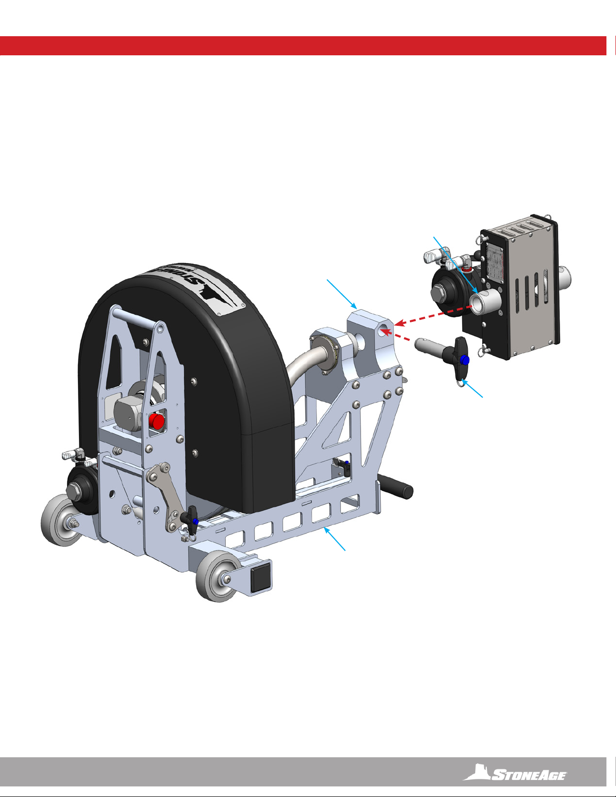
1. Remove Quick Release Pin from Base Frame Assembly. Install the Hose Drum Assembly onto the Base Frame Assembly by placing
the shoulder screw heads into the notches on the Joint Plates and inserting the Quick Release Pin through the holes in the Joint
Plates. (Figure 1)
HOSE DRUM ASSEMBLY TO BASE FRAME ASSEMBLY
HOSE DRUM
ASSEMBLY
JOINT
PLATES
QUICK
RELEASE PIN
BASE FRAME
ASSEMBLY
FIGURE 1
11
866-795-1586 • WWW.STONEAGETOOLS.COM
NAVIGATOR SET-UP
FIGURE 2
ABX-PRO PRODRIVE TO BASE FRAME ASSEMBLY
NAVIGATOR SET-UP
QUICK
RELEASE PIN
2. Remove Quick Release Pin from Base Frame Assembly, Install the ABX-PRO PRODRIVE onto the Base Frame Assembly by sliding the
Guide Tube into the Drive Mounting Block and inserting the Quick Release Pin. (Figure 2)
BASE FRAME
ASSEMBLY
DRIVE
MOUNTING
BLOCK
GUIDE TUBE

12 866-795-1586 • WWW.STONEAGETOOLS.COM
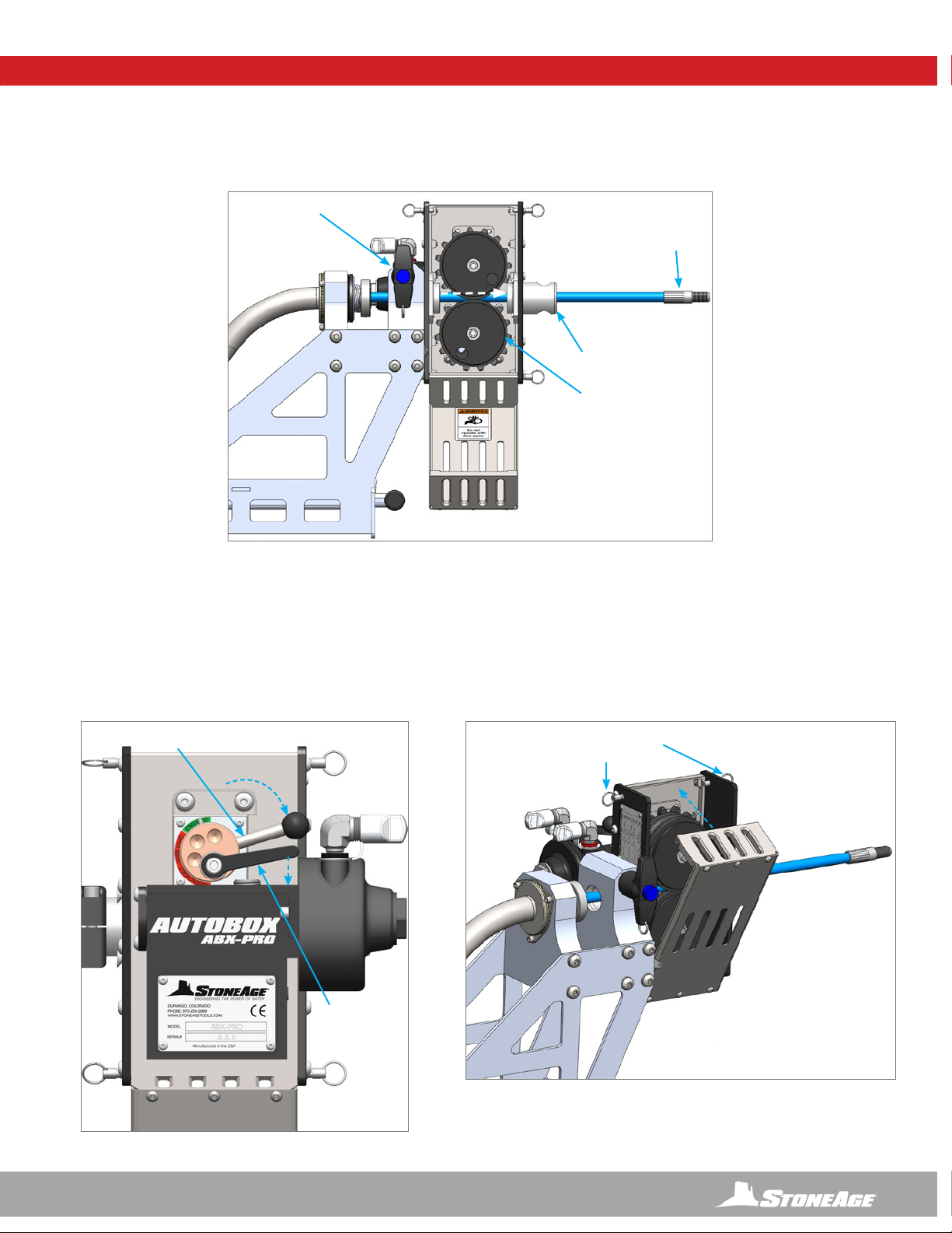
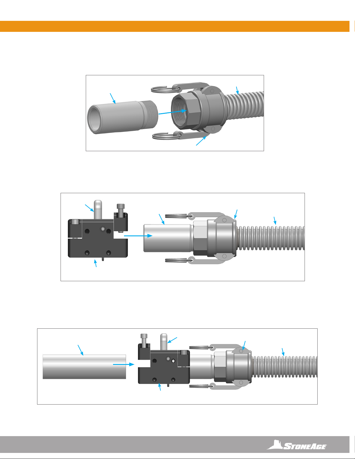
1. Connect the female hose end to the hose connection tube and wind the hose in the direction of the arrow inside the drum. (Figure 1)
NAVIGATOR SET-UP
ECCENTRIC
LEVER
HOSE
CONNECTION TUBE
DIRECTIONAL
ARROW
ELBOW
FIGURE 1
2. Load the hose into the ABX-PRO tractor by releasing the Adjustable Handle and rotating the Cam Lever counterclockwise until the
Indicator Pin is in the “Disengaged” position. This will open up the space between the rollers to allow for the hose to slip between
them. (Figure 2)
CAM LEVER
ADJUSTABLE
HANDLE
INDICATOR
PIN
FIGURE 2
LOADING THE HIGH-PRESSURE HOSE
NOTICE
Only high quality hoses intended for waterblast applications should be used as high-pressure hoses. Pressure rating of high-pressure hoses
MUST NEVER be exceeded. Do not use a shrouded hose or hose with a steel protective cover. This will cause severe damage to the Rollers.
13
866-795-1586 • WWW.STONEAGETOOLS.COM
NAVIGATOR SET-UP NAVIGATOR SET-UP
3. With the Rollers open, slip the hose through the Drive Block, Rollers and Guide Tube. Be sure to pull enough extension to feed through
the Snout. (Figure 3)
FIGURE 3
MALE
HOSE
END
ROLLERS
GUIDE
TUBE
DRIVE
BLOCK
4. Rotate the Cam Lever clockwise to the “Engaged” position to tighten the Idler Roller down onto the hose. Push the Adjustable Handle
down to tighten the bushing assembly. (Figure 4)
5. Push the back cover back into the closed position and secure the two Quick Release Pins on the top of the ABX-PRO AUTOBOX®
PRODRIVE TRACTOR. (Figure 5)
FIGURE 4
FIGURE 5
QUICK RELEASE
PINS
CAM
LEVER
ADJUSTABLE
HANDLE
“ENGAGED”
14 866-795-1586 • WWW.STONEAGETOOLS.COM
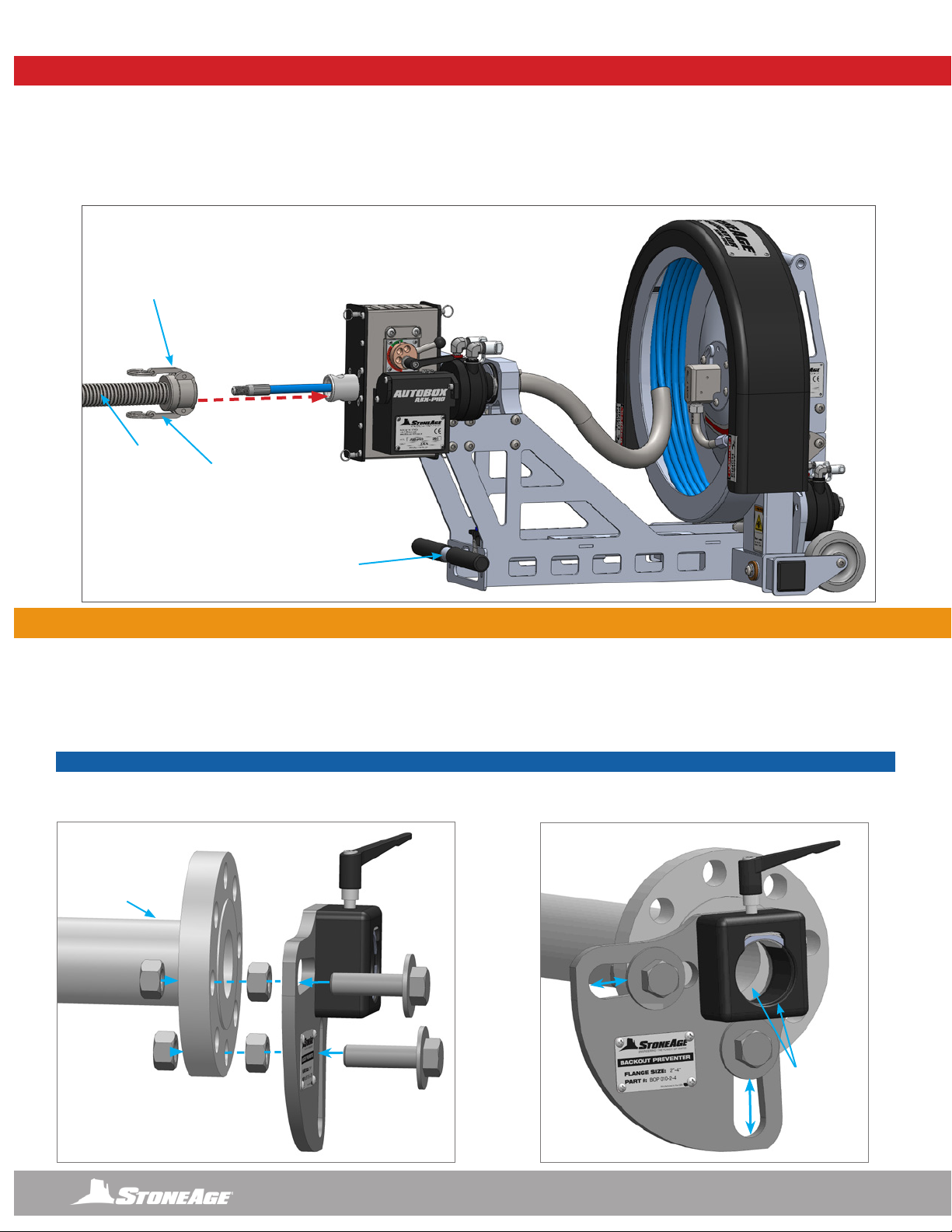
SNOUT ASSEMBLY TO ABX-PRO PRODRIVE
SNOUT
ASSEMBLY
1. Pull on the Camlock Release Rings and slide the Camlock onto the male end of the ABX-PRO PRODRIVE. Push the Camlock pins
back to lock into place. (Figure 1) Pull on the Snout Assembly to make sure it is secured. Feed the rest of the hose through the Snout
Assembly and leave enough length to feed through a pipe ange attachment.
NAVIGATOR SET-UP
BASE FRAME
ASSEMBLY
CAMLOCK
END
CAMLOCK
RELEASE RING
FIGURE 1
QUARTER PLATE FLANGE MOUNT (BOP 010-2-4 QTR) TO PIPE
1. Attach the Quarter Plate Flange Mount to the pipe ange using the fasteners that were removed from the ange joint. The nuts shown
between the pipe ange and the Quarter Plate Flange Mount are to allow for drainage. Other spacer options are acceptable. (Figure 1)
2. Adjust the Quarter Plate Flange Mount by sliding it along the slots to center the inside diameter of the Hinge Clamp with the inside
diameter of the pipe. Tighten all hardware to secure in place. (Figure 2)
FIGURE 1 FIGURE 2
USE FASTENERS
REMOVED FROM THE
FLANGE JOINT
ALIGN INSIDE
DIAMETERS
Pipe shown
for graphic
representation only.
Not included in
assembly.
QUARTER PLATE FLANGE MOUNT ASSEMBLY SET-UP - INCLUDED
NOTICE
If the cleaning tool diameter is larger than the inside diameter of the snout tubes, the high pressure hose will need to be fed through the
Quarter Plate Flange Mount before installing the tool on the male hose end. Skip to the next page if this is necessary.
15
866-795-1586 • WWW.STONEAGETOOLS.COM
QUARTER PLATE FLANGE MOUNT ASSEMBLY SET-UP - INCLUDED
SNOUT CONNECTION AND BACKOUT PREVENTION ASSEMBLY
3. Thread the BOP 084 Threaded Snout Tube into the BOP 085 Camlock at the end of the BOP 090 Snout. (Figure 3)
4. Loosen the two screws on the collet cap block and slide the BOP 030 Collet Block Assembly onto the BOP 084 Threaded Snout Tube.
Push the Collet Block until it stops on the Snout Tube, then tighten the two screws securely. (Figure 4)
5. Loosen the two screws on the collet cap block and slide the BOP 081-6 Snout Tube into the BOP 030 Collet Block Assembly.
Push the Snout Tube until it stops in the Collet Block Assembly, then tighten the two screws securely. (Figure 5)
FIGURE 3
FIGURE 4
FIGURE 5
SNOUT
BOP 090
SNOUT
BOP 090
BOP 084
THREADED SNOUT
TUBE
BOP 084
THREADED SNOUT
TUBE
BOP 030 COLLET
BLOCK ASSEMBLY
BOP 030 COLLET
BLOCK ASSEMBLY
BOP 081-6
SNOUT TUBE
BOP 085
CAMLOCK
BOP 085
CAMLOCK
FF-121-XXX
COLLET
FF-121-XXX
COLLET SNOUT
BOP 090
BOP 085
CAMLOCK
16 866-795-1586 • WWW.STONEAGETOOLS.COM
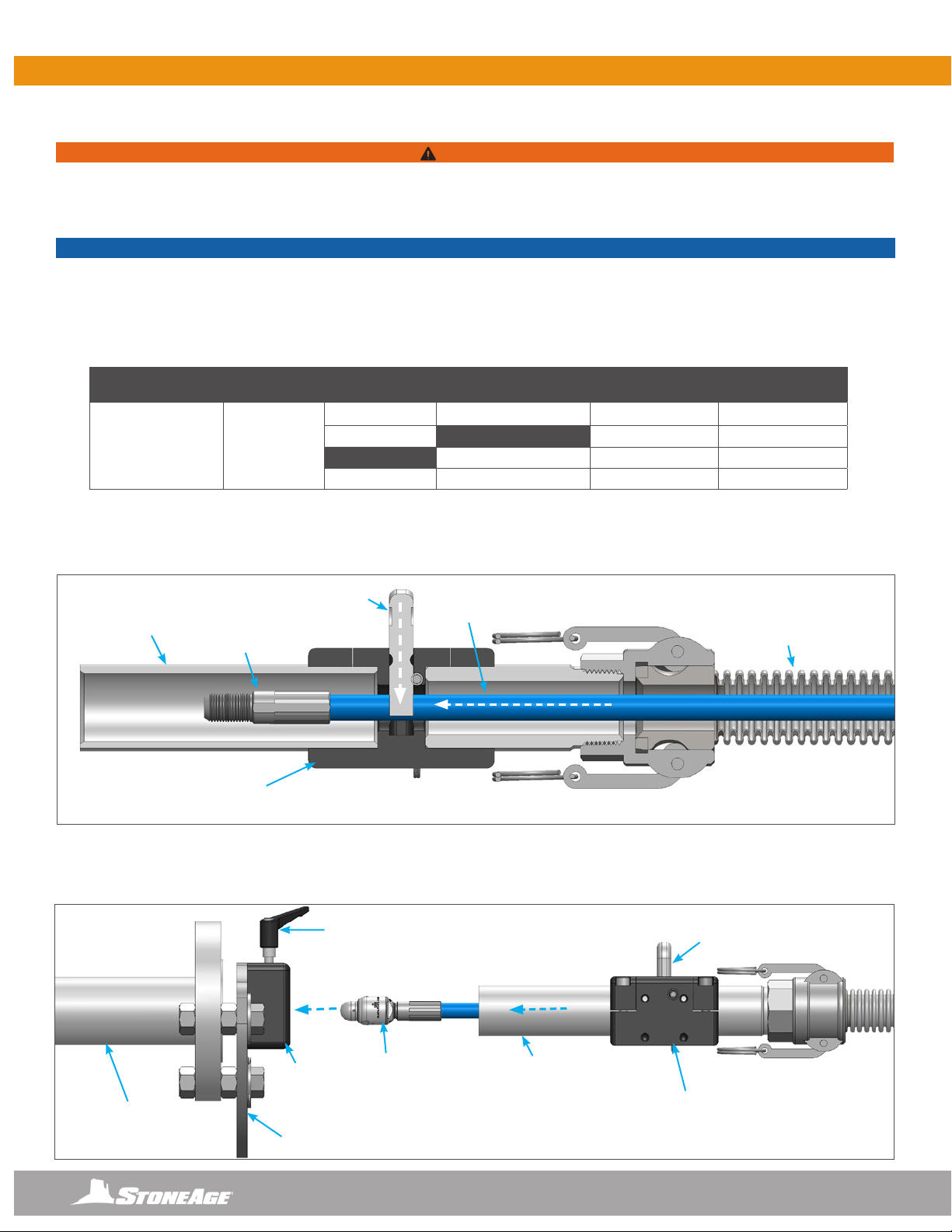
QUARTER PLATE FLANGE MOUNT ASSEMBLY SET-UP - INCLUDED
MALE
HOSE END
BOP 010-2-4 QTR
QUARTER PLATE FLANGE MOUNT
ADJUSTABLE
HANDLE
TOOL
Pipe shown for graphic
representation only.
Not included in assembly.
HIGH PRESSURE
HOSE
SECTION VIEW
HINGE
CLAMP
6. Remove the Quick Release Pin and the Collet from the Collet Block Assembly. Push the Male Hose End past the Collet and reinsert
the Collet and Quick Release Pin. Test the collet by pulling the hose in the reverse direction of installation to ensure the Male Hose
End does not back out past the Collet. (Figure 6)
7. Attach desired tool onto the male hose end (Stoneage® Beetle®shown for reference). SEE THE APPLICABLE TOOL MANUAL
FOR INSTALLATION INSTRUCTIONS. Loosen the adjustable handle on the Hinge Clamp. Feed the high pressure hose with tool and
Snout Tube into the Quarter Plate Flange Mount. Tighten the adjustable handle to secure. (Figure 7)
BOP 030 COLLET
BLOCK ASSEMBLY
BOP 030 COLLET
BLOCK ASSEMBLY
BOP 081-6
SNOUT TUBE
FF-121-XXX
COLLET
SNOUT
BOP 090
FF-121-XXX
COLLET
FIGURE 7
FIGURE 6
BOP 081-6
SNOUT TUBE
POLY ROLLER
ABX-PRO HOSE O.D. SPIR STAR PARKER COLLET SIZE
STONEAGE
PART NUMBER
PRO 174-46
ø0.46 IN.
0.39 - 0.50 IN.
9.9 - 12.7 MM
4/4 2440D-025 0.438 in. / 11.0 mm FF 121-438
5/4 0.460 in. / 11.7 mm FF 121-460
2440D-03 0.484 in. / 12.3 mm FF 121-484
6/4 2440D-04 0.516 in. / 13.0 mm FF 121-516
SNOUT CONNECTION AND BACKOUT PREVENTION COLLET
NOTICE
The NAVIGATOR NAV-100 comes with one customer specied FF 121-XXX Collet installed in the BOP 030 Collet Block Assembly. It is
necessary to change the Collet size when changing to a different diameter hose. There are additional roller and collet sizes beyond the list
below that are only to be used when operating the ABX-PRO as part of the ABX-PRO-100 PRODRIVE Assembly. THE REPLACEMENTS
SHOWN IN THE CHART BELOW ARE THE ONLY SIZES TO BE USED WITH THE NAVIGATOR ASSEMBLY. Additional information on the
ABX-PRO-100 PRODRIVE Assembly can be found in the ABX-PRO-100 PRODRIVE manual at WWW.STONEAGETOOLS.COM.
WARNING
Prior to use, always test the backout preventer to ensure the tool does not pass backward through the Collet Block Assembly. Failure to do
so can result in severe injury and/or death. It is the responsibility of the user to select proper collet sizing to assure the end of the hose will
not pass through the Collet. Use the chart below in to select proper collet size.
17
866-795-1586 • WWW.STONEAGETOOLS.COM
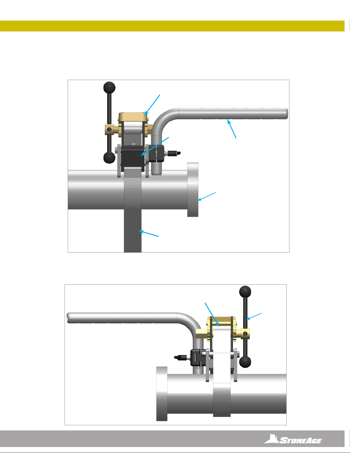
STRAP MOUNT ASSEMBLY SET-UP- OPTIONAL
The Strap Mount Assembly (BOP 050) is designed for pipes that do not have anges.
1. Attach the strap end to the strap capture bar and wrap the strap around the pipe towards the Winch Assembly. (Figure 1)
2. Pull excess strap through the Winch Assembly and tighten down with the Ball End Handle. (Figure 2)
FIGURE 1
FIGURE 2
STRAP END TO
CAPTURE BAR
MALE
POSITIONER
BAR
WINCH
ASSEMBLY
STRAP
BALL END
HANDLE
PULL EXCESS
STRAP THROUGH
STRAP MOUNT ASSEMBLY (BOP 050) - MALE POSITIONER SIDE
Pipe shown for graphic
representation only.
Not included in assembly.

18 866-795-1586 • WWW.STONEAGETOOLS.COM
FIGURE 3
3. Release the Adjustable Handle on the BOP 070 Hinge Clamp to access the 4 socket head cap screws. Locate the side of the BOP
030 Collet Block Assembly with 4 threaded holes. Orient the Hinge Clamp so that the hinge is on the right. Fasten the Hinge Clamp
Assembly to the Collet Block Assembly using the 4 supplied socket head cap screws. (Figure 3)
4. Insert the BOP 058 Female Positioner Assembly into the Hinge Clamp Assembly. This can be done in the open or closed position and
is designed to be adjustable based on the size of the pipe. (Figure 4)
5. Close the Hinge Clamp Assembly and tighten the Adjustable Handle. To Install the BOP 012 OPTIONAL Splash Plate loosen the two
bolts on the collar, slide it onto the BOP 081-6 Snout Tube and hand tighten the collar bolts when in position. (Figure 5)
STRAP MOUNT ASSEMBLY (BOP 050) - FEMALE POSITIONER SIDE
BOP 030 COLLET
BLOCK ASSEMBLY
BOP 058 FEMALE
POSTIONER
ASSEMBLY
SOCKET HEAD CAP
SCREWS (4)
BOP 070
HINGE CLAMP
ASSEMBLY
BOP 070
HINGE CLAMP
ASSEMBLY
COLLAR
COLLAR
BOLTS
ADJUSTABLE
HANDLE
FF-121-XXX
COLLET
FIGURE 4 FIGURE 5
ADJUSTABLE
HANDLE
*OPTIONAL BOP 012
SPLASH PLATE
STRAP MOUNT ASSEMBLY SET-UP- OPTIONAL
19
866-795-1586 • WWW.STONEAGETOOLS.COM
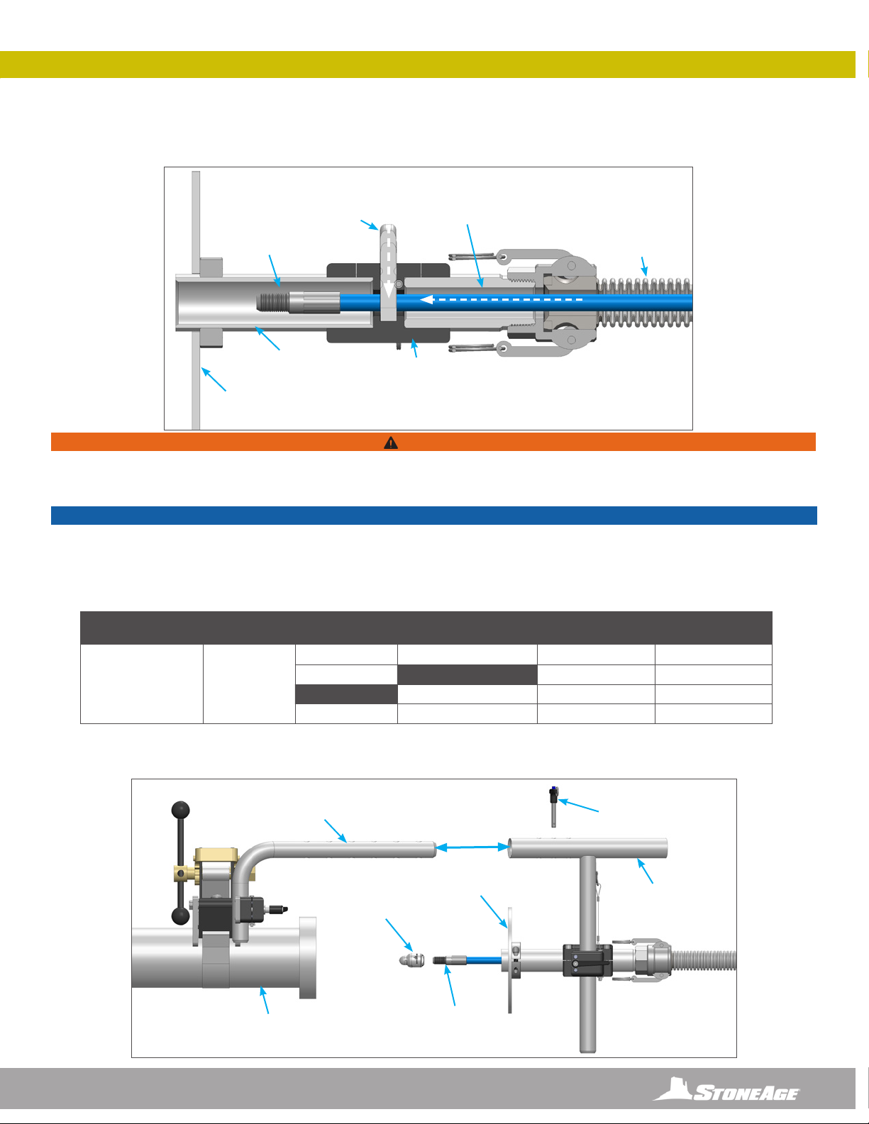
STRAP MOUNT ASSEMBLY SET-UP- OPTIONAL
5. Attach desired tool onto the male hose end (Stoneage® Beetle®shown for reference). SEE THE APPLICABLE TOOL MANUAL
FOR INSTALLATION INSTRUCTIONS. Connect the Male and Female Positioner Arms. Select the appropriate positioning holes and
insert the Quick Release Pin through both arms. (Figure 7)
DRIVE SIDE TUBE MOUNT AND BACKOUT PREVENTION COLLET
STRAP MOUNT ASSEMBLY SET-UP- OPTIONAL
FIGURE 6
TOOL
MALE HOSE
END
MALE
POSITIONER
ARM
FEMALE
POSITIONER
ARM
QUICK
RELEASE PIN
*OPTIONAL BOP 012
SPLASH PLATE
MALE
HOSE END
HIGH PRESSURE
HOSE
SNOUT
BOP 090
FF-121-XXX
COLLET
6. Remove the Quick Release Pin and the Collet from the Collet Block Assembly. Push the Male Hose End past the Collet and reinsert
the Collet and Quick Release Pin. Pull back on the hose to ensure the Male Hose End does not back out past the Collet. (Figure 6)
*OPTIONAL BOP 012
SPLASH PLATE
BOP 030 COLLET
BLOCK ASSEMBLY
BOP 081-6
SNOUT TUBE
FIGURE 7
Pipe shown for graphic
representation only.
Not included in assembly.
POLY ROLLER
ABX-PRO HOSE O.D. SPIR STAR PARKER COLLET SIZE
STONEAGE
PART NUMBER
PRO 174-46
ø0.46 IN.
0.39 - 0.50 IN.
9.9 - 12.7 MM
4/4 2440D-025 0.438 in. / 11.0 mm FF 121-438
5/4 0.460 in. / 11.7 mm FF 121-460
2440D-03 0.484 in. / 12.3 mm FF 121-484
6/4 2440D-04 0.516 in. / 13.0 mm FF 121-516
NOTICE
The NAVIGATOR NAV-100 comes with one customer specied FF 121-XXX Collet installed in the BOP 030 Collet Block Assembly. It is
necessary to change the Collet size when changing to a different diameter hose. There are additional roller and collet sizes beyond the list
below that are only to be used when operating the ABX-PRO as part of the ABX-PRO-100 PRODRIVE Assembly. THE REPLACEMENTS
SHOWN IN THE CHART BELOW ARE THE ONLY SIZES TO BE USED WITH THE NAVIGATOR ASSEMBLY. Additional information on the
ABX-PRO-100 PRODRIVE Assembly can be found in the ABX-PRO-100 PRODRIVE manual at WWW.STONEAGETOOLS.COM.
WARNING
Prior to use, always test the backout preventer to ensure the tool does not pass backward through the Collet Block Assembly. Failure to do
so can result in severe injury and/or death. It is the responsibility of the user to select proper collet sizing to assure the end of the hose will
not pass through the Collet. Use the chart below in to select proper collet size.

20 866-795-1586 • WWW.STONEAGETOOLS.COM
TIGHT PIPE FLANGE JOINT ATTACHMENT OPTIONS
QUARTER PLATE BOP
BOP 010-2-4 QTR
Pipe shown for graphic
representation only. Not
included in assembly.
(INCLUDED WITH NAVIGATOR PACKAGE)
TIGHT PIPE FLANGE JOINT ATTACHMENT OPTIONS
(NOT INCLUDED WITH NAVIGATOR PACKAGE)
BOP 012 SPLASH PLATE
BOP 050 STRAP
MOUNT ASSEMBLY
NAV-100 NAVIGATOR ASSEMBLY
WITH STRAIGHT MOUNTING OPTIONS
*THE MOUNTING OPTION BELOW IS USED ON FLANGED PIPES*
*THE MOUNTING OPTION BELOW IS USED ON FLANGELESS PIPES*
Pipe shown for graphic
representation only. Not
included in assembly.
This manual suits for next models
1
Table of contents


