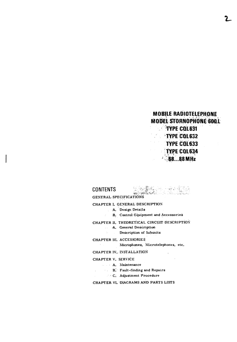
Storno Stornophone 600 User manual

MOBILE
RADIOTELEPHONE
MO
DEL
STORNOPHONE
600
TYPE
CQM611
CONTENTS
GENERAL
SPECIFICATIONS.
CHAPTER
I.
GENERAL
DESCRIPTION.
A.
Design
Details
B.
Control
Equipment
CHAPT'ER
II.
THEORETICAL
CIRCUIT
ANALYSIS.
A.
General
Description
Description
of
subunits
CHAPTER
III.
ACCESSORIES.
Control
Boxes
Microphones,
Microtelephones,
etc.
CHAPTER
IV.
ll'lSTALLATION.
A.
General
B.
Installation
of
the
Radio
Equipn1ent
TYPE
CQM612
TYPE
CQM613
TYPE
CQM614
146
...
174MHz
C.
Installation
of
Standard
Control
Equipment
D.
Installation
of
Waterproof
Control
Equipn1ent
E.
Standard
Antennas
F.
Noise
Suppression
G.
Testing
of
lnstalled
Equipment
CHAPTER
V,
SERVICE.
A.
Maintenance
B.
Fault-finding
and
Repairs
C.
Adjustrnent
Procedure
CHAPTER
VI. DIAGRA.IVIS
AND
PARTS
LISTS.
5toP.NO
CHAPTER
VU.
MECHANICAL
PARTS
LISTS.
•."
' •/j'\
~·""'
\.
''[
L~
:
'·~
The document reference is online, please check the correspondence between the online documentation and the printed version.

The document reference is online, please check the correspondence between the online documentation and the printed version.

Storno Storno
GENERAL
SPECIFICATIONS
Type
CQM611
CQM612
CQM613
CQM614
Freql.!ency
range
146-174
MHz 146 -1741\IIHz
146-174
MHz
146
-1
74
1\tiH
z
Min.
channel
spacing
50
kHz
25kHz
20kHz
12.
5kHz
Max.
frequency
deviation
:15kHz
:5kHz
:4kHz
:2.5
kHz
F
requency
stability
Conforma
with
Government
Regulations
Max.
bandwidth
1000
kHz
Antenna
impedance
50 a
nominal
Number
of
RF
...
channels
Max.
12
Dimensions,
transmitter/
340 x
190
x 85
mm
(13
1/3
11
x 7
1/2
11
x 3
3/4")
receiver
Dimensions,
control
box
CB601
14
0 x 150 x 50
mm
(5
1/2
11
x
6"
x 2
11
)
Weight,
transmitter
/
receiver
'5.
2
kg
(
11.
5
lbs)
Weight,
control
box
CB601
o.
6
kg
(1.
3
lbs)
TRANSMITTER
SPECIFICATIONS
RF-output
power
10
watt
with
possibility
of
reduction
to
lower
output
?ower
Modulation
CQM611,
CQl\11612,
and
CQlVI613:
Phase
modulation
300-3000
Hz
CQM614:
Phase
modulation
300-2600
Hz
FM
noise
CQM611:
50
dB
below
standard
test
modulation
CQM612,
CQM613,
CQlVI614: 40
dB
below
standard
test
modulation
Spurious
and
Harmonie
-7
radiation
Below
2 x 10
watts
RECEIVER
SPECIFICATIONS
Sensitivity
O.
35
IJV
at
20
dB
S/N
(with
duplex
filter
BF612:
O.
5
JJV)
Squelch
Electronic,
adjustable
Adjacent
channel
selectivity
CQM611, CQM612,
CQM613:
85
dB
(EIA
two-signal
method)
CQM614:
:10.
2
kHz
(GPO
measuring
method).
1
Less
than
2 x
10""
9
watts
Spurious
radiation
Intermodulation
CQM611, CQM612,
CQM613:
70
dB
(EIA
measuring
method)
CQM614:
58
dB
(GPO
measuring
method)
Image
and
spurious
attenuation
CQM611, CQM612,
CQM613:
Min.
85
dB
CQM614:
Min.
75
dB
AF
-output
power
2
watts,
adjustable
POWER
SUPPLY
SPECIFICATIONS
Battery
volta
ge
6,
3 v
12.6
v
25.2
v
Current
consumption:
Stand-by
O.
55 A
o.
25 A
0.14
A
Transmit
s.
0
3.
2
1.
5
31.
065-E2
31.
065-E2
The document reference is online, please check the correspondence between the online documentation and the printed version.

The document reference is online, please check the correspondence between the online documentation and the printed version.

Stome
CHAPTER
1.
GENERAL
DESCRIPTION
A.
Design
Details
Introduction
The
STORNOPHONE
600
mobile
radiotelephone
is
a
transmitter/receiver
combination
for
sim-
plex
or
duplex
operated
Fl\11
radio
communication
in
one
of
the
following
frequency
ranges:
68-88
Mc/s.
146-174
Mc/s,
and
420-470
Mc/s.
The
complete
radiotelephone
comprises
a
trans-
mitter/receiver
cabinet,
a
control
box., a
micro
...
phone
or
handset,
and
antenna
and
installation
mate
rials.
This
manu
al
con
tains
a
detailed
description
of
the
STORNOPHONE
600
and
the
standard
ac-
31.
060-E2
1-1
cessories
which
are
available.
Because
we
at
STORNO
are
constantly
processing
the
ex-
perience
we
gain
during
the
production.,
testing,
and
operation
of
our
radiotelephones,
miner
modifications
and
corrections
will
be
made
re-
gularly.
The
se
will
be
listed
on a
separa
te
sheet,
which
will
be
placed
!irst
in
this
manual.
If
your
STORNOPHONE
600
is
a
special
version,
descriptions
of
the
necessary
modifications
will
be
condensed
into
an
appendix
which
is
placed
first
in
the
standard
description
whilst
the
as-
sociated
circuit
diagrams
are
placed
last
in
the
book.
31.
060-E2
The document reference is online, please check the correspondence between the online documentation and the printed version.

Stomo
Standard
Versions
The
STORNOPHONE 600
is
available
in
the
follow-
ing
versions
for
either
simplex
or
duplex
opera-
tion:
Type
Frequency
Range
Channel
Separation
CQM611 146 -174 MHz
50
kHz
CQM612 146 -174
MHz
25
kHz
CQM613
146-
174 MHz
20
kHz
CQM614 146
-4
174
MHz
12.5
kHz
CQM631
68-
88
MHz
50
kHz
CQM632
68-
88 MHz
25
kHz
CQM633
68-
88 MHz
20
kHz
CQM634
68-
88 MHz
12.5
kHz
CQM661 420 -470 MHz 50 kHz
CQM662 420 -470 MHz
25
kHz
CQM663 420 -470 MHz
20
kHz
Where
it
is
not
necessary
to
distinquish
between
radiotelephones
with
different
channel
separa-
tions,
the
following
description
will
employ
corn-
mon
designations
for
radiotelephones
inside
the
same
t'requency
band.
Thus,
the
CQM611,
CQM612, CQM613,
and
CQM614
2-metre
radio-
telephones
will
be
covered
under
the
common
designation
of
CQM610.
The
STORNOPHONE 600
can
be
operated
from
12-
and
24-volt
DC
power
supplies.
The
voltage
changeover
operation
is
performed
outside
the
transmitter
/receiver
cabinet
and
is
very
easy
to
make.
A
maximum
of
12
RF
channels
can
be
pro-
vided.
For
2-
and
4-metres
radiotelephones
the
trans-
mitter
power
output
is
10
watts.
and
for
O.
7-
metres
radiotelephones
12
watts
with
provision
for
operation
at
reduced
power.
Space
is
provided
in
the
transmitter
/receiver
cabinet
for
an
additional
receiver
converter
for
use
in
the
maritime
and
similar
services
where
larger
bandwidth
of
the
receiver
input
circuits
is
required.
A
comprehensive
Une
of
standard
tone
equipment
makes
it
possible
to
add
various
forms
of
selective
calling
systems
to
the
STORNOPHONE 600.
The
choice
is
not
limited
by
the
space
available
in
the
transmitter
/receiver
cabinet
as
all
tone
equip-
31.
060-E2
1-2
Storno
mentis
designed
for
installation
in
the
control
box.
Construction
The
transmitter
/receiver
equipment
is
housed
in
a
die-cast
cabinet
which
is
both
dust-proof
and
splash-
proof.
The
lid
and
bottom
of
the
ca-
binet
are
heavily
fluted
so
that
they
can
carry
a
maximum
of
heat
away
from
the
equipment.
Inside,
the
cabinet
is
divided
into
three
compartments;
these
accomodate
the
transmitter.
receiver,
and
power
supply
sections.
The
transmitter
section
becomes
accessible
on
removal
of
the
lid
of
the
cabinet
whilst
removal
of
the
bottom
plate
per-
mits
direct
access
to
the
receiver
section
and
the
power
supply
section.
A
multiwire
connecter
on
the
cabinet
provides
connection
for
multiwire
cable
and
battery
cable,
and
a
voltage
switch
on
the
side
of
the
cabinet
permits
switching
between
battery
voltages
of
12
and
24
volts.
Furthermore
the
cabinet
of
simplex
operated
ra-
diotelephones
has
an
antenna
connecter
whereas
the
duplex
versions
have
two
antenna
connectors
which
provide
connections
for
both
receiver
and
transmitter
antennas
or
a
bran
ching
filter.
Bath
the
transmitter
and
the
receiver
consists
of
a
number
of
modules
built
on
printed
wiring
boards.
These
are
screw-mounted
side
by
side
in
the
ca-
binet,
with
their
components
facing
outwards.
The
power
supply
section
is
an
integral
unit
having
only
one
wiring
board.
with
its
wiring
side
facing
outwards.
This
unit,
as
well
as
the
transmitter
and
receiver
modules,
are
easily
removable
from
the
cabinet;
the
only
thing
to
do
is
loosen
the
screws
which
hold
particular
unit
in
place.
31.
060-E2
The document reference is online, please check the correspondence between the online documentation and the printed version.

Storno
Stomo
Chapter
1.
General
Description
section
is
an
integral
unit
having
only
one
wiring
board,
with
its
wiring
side
facing
outwards.
This
unit.
as
well
as
the
transmitter
and
re-
ceiver
modules,
are
easily
removable
from
the
cabinet;
the
only
thing
to
do
is
to
loosen
the
screws
which
hold
the
particular
unit
in
place.
B.
Control
Equipment
The
accessories
listed
below
are
available
for
use
with
the
transmitter
/recei
ver
unit.
They
are
grouped
solely
for
practical
reasons.
For
instan-
ce,
there
is
nothing
to
prevent
use
of
the
water-
tight
control
box
with
the
non-watertight
handset.
Standard
Control
Equipment
This
group
of
control
equipment
will
normally
be
employed
in
passenger
cars,
in
commercial
ve-
hicles,
and
in
buses
etc.
where
the
equipment
will
not
be
directly
exposed
to
moisture,
so
that
watertight
or
particularly
rugged
construction
is
not
a
requirement.
CB601.
Control
box
of
die-cast
light-alloy
metal
with
control
knobs
and
lamps
on
the
front
panel.
An
LS601
laud-
speaker
(
see
below)
can
be
fastened
to
the
bottom
of
the
box.
A
loudspeaker
amplifier
and
various
types
of
tone
equipment
can
be
installed.
Mounting
hardware
is
supplied
with
the
box.
LS601.
High-efficiency
loudspeaker.
Mounting
hardware
is
supplied.
MC601.
Fixed
microphone
with
built-in
ampli-
fier.
Mounting
hardware
is
supplied.
MC602.
Fixed
microphone
with
built-in
ampli-
fier
and
10-cm
gooseneck.
MC603.
Fixed
microphone
with
built-in
ampli-
fier
and
20-cm
gooseneck.
MC604.
Fixed
microphone
with
built-in
ampli-
fier
and
40
-cm
gooseneck.
MC606.
Fist
microphone
with
built-in
amplifier.
push-to-talk
key,
and
hang-up
bracket.
Mounting
hardware
is
supplied.
MT601.
Handset
with
built-in
amplifier.
push-to-
talk
key,
and
hang-up
bracket.
Mounting
hardware
is
supplied.
31.060-E2
1-3
MT6
01.
Handset
with
built-in
amplifier,
push
-t<
talk
key,
and
hang-up
bracket.
Mountin
hardware
is
supplied.
Watertight
Control
Equipment
This
group
of
control
equipment
wil
normally
be
used
in
open
vehicles,
(lorries,
fork
lifts,
tractors,
etc.
L
in
ships,
and
in
locomotives
etc.
This
equipment
is
watertight
and
dusttight
as
well
as
corrosion-proof
and
saltwater-proof;
it
is
also
rugged
and
consequently
will
stand
up
to
rough
handling.
The
size
and
shape
of
the
control
lmobs
permit
them
to
be
operated
by
a
persan
wearing
working
gloves.
Lastly,
this
equipment
is
designed
for
use
under
con-
ditions
of
high
ambient
noise.
CB602.
Watertight
control
box
in
grey
die
..
cast
light-alloy
metalJ
with
heavy-
duty
control
knobs
(military
type).
A
loudspeaker
an1plifier
and
various
types
of
tone
equipment
can
be
in-
stalled
in
the
box.
Mounting
hard-
ware
is
supplied.
LS602.
Watertight,
saltwater-proof
folded-
horn
loudspeaker.
MT6
02.
Watertight,
impact
-proof
handset
with
built-in
amplifier
and
trans-
mit
butten.
Normally,
the
MT602
handset
is
permanently
connected
to
the
control
box
but
can
be
supplied
with
watertight
plug
if
desired.
A
helder
and
monnting
hardware
are
supplied.
31.
060-E2
The document reference is online, please check the correspondence between the online documentation and the printed version.

Storno
Stomo
Chapter
1.
General
Description
Antennas
The
STORNOPHON~
600
is
designed
for
oper-
ation
with
a
50-ohm
antenna.
STORNO
can
supply
the
following
standard
types,
ail
of
which
have
bases
designed
ta
permit
mounting
fro~
the
outside
without
damaging
the
car
up-
holstery.
AN39-5
114
wavelength
whip
antenna
for
the
frequency
range
68-88
MHz.
AN19-5
1/4
wavelength
whip
antenna
for
the
frequency
range
146
·174
MHz.
AN69·3
1/4
wavelength
whip
antenna
for
the
frequency
range
420-470
MHz.
AN69-4
5/8
wavelength
whip
antenna
for
the
frequency
range
420-470
IviHz.
Other
types~
su
ch
as
a
51
8
-wa
v
elen
gth
re
ar
..
mounting
antenna,
tilt-over
antenna
or
mag-
netic
antenna
may
be
used
if
desired.
Branching
Filters
The
bran
ching
filters
specified
below
are
used
with
radiotelephones
for
duplex
operation.
when
the
transmitter
and
the
receiver
are
to
be
con-
nected
to
the
same
antenna.
The
filter
is
housed
in
a
die
-cast
cabinet
similar
to
that
of
the
transmitter
/receiver.
It
can
be
mounted
either
on
top
of
the
transmitter
/re-
ceiver
cabinet,
for
which
purpose
mounting
hardware
is
supplied,
or
separately
by
means
of
an
installation
kit
No.
3"7.
065
(see
under
In-
stallation
Kit).
BF632
BF612
BF662
Branching
filter
for
the
frequency
range
68-88
MHz.
Branching
filter
for
the
frequency
range
146-174
MHz.
Branching
filter
for
the
frequency
range
420-470
MHz.
Installation
l<it
In
addition
to
a
number
of
the
accessories
listed
above,
the
installation
of a
STORNOPHONE
600
radiotelephone
requires
a
kit
of
parts.
These
are
specified
below:
17.014
Standard
kit
of
accessories
consisting
of
multiwire
connecter
for
control
31.
06Ù-E2
1-4
19.
06 3
cable.
antenna
connecter,
fuse
helder
and
set
of
cable
shoes
for
battery
cable.
Standard
installation
kit
consisting
of
6
metres
of
multi-core
cable,
8
metres
of
battery
cable,
and
4
metres
of
anten-
na
cable.
These
lengths
are
sufficient
for
installing
a
radiotelephone.
even
in
large
vehicles.
Also
available
are:
37.065
37.072
Mounting
plate
with
hardware
and
screws
for
mounting
the
transmitter
1
receiver
cabinet
or
a
branching
filter.
Mounting
strap
with
hardware
and
screws
for
mounting
the
transmitter
1
recei
ver
cabinet.
Tone
Equiprnent
The
STORNOPHONE
600
has
provision
for
sub-
sequent
addition
of
tone
equipment.
The
instal-
lation
job
is
simple.
space
for
a
tone
transmit-
ter
and
a
tone
receiver
having
been
provided
in
the
control
box.
Additional
space
for
an
alarm
circuit
is
also
a
vailable
in
the
control
box.
If
the
STORNOPHONE
600
is
supplied
with
tone
equipment,
you
will
find
descriptions.
circuit
diagrams
etc.
of
such
equipment
in
a
separate
technical
manual.
Installation
Instructions
Brief
installation
instructions
are
supplied
with
each
individual
accessory.
However.
Chapter
4
of
this
manual
contains
a
complete
description
of
how
to
install
bath
the
transmit-
ter/receiver
cabinet
and
the
accessories.
Otherwise.
STORNO
will
be
glad
to
supply
ali
such
information
as
cannat
be
obtained
by
a
study
of
this
manual.
Operation
A
booklet
containing
very
detailed
operating
instructions
is
supplied
with
the
STORNOPHONE
600.
Accordingly.
this
manual
contains
no
oper-
ating
instructions.
31.
060-E2
The document reference is online, please check the correspondence between the online documentation and the printed version.

Storno
CHAPTER
Il.
THEORETICAL
CIRCUIT
ANALYSIS
A.
General
Description
146
-
174
Mc/s
Equipment
RX
ANt>----..------1
!DUPlEX! 1
1
1
1
1
1
1
1
1
r-..J.--,
ANT
>-~
AS631
~
t
ISIMPt.fXI
1
--ï-~
1
1
1
1
1
1
1
1
1
TX
Nff
>---
------1
lOOPleXI
XSS01
XS601
Bath
the
receiver
and
the
transmitter
are
di-
vided
into
a
nwnber
of
subunits
each
ot
which
is
built
on
printed
wiring
boards.
This
division
has
been
made
in
order
to
make
the
equipment
easily
accessible
for
adjustments
and
repaira,
and
follows
strictly
logicallines.
The
receiver
and
the
transmitter
use
silicon
transistors
throughout,
resulting
in
less
de-
pendance
on
ambient
temperature
and
in
greater
reliability.
Receiver
Section
The
receiver
is
a
double-conversion
superhetero-
dyne
using
intermediate
frequencies
of
10,7
Mc/s
and
455
kc/s.
The
necessary
selectivity
is
ob-
tained
by
means
of
two
block
fllters.
A
maximum
of
12
crystal
oscillators
-
one
for
each
frequency
channel
-
can
be
provided.
The
receiver
is
com-
posed
of
the
followin
g
modules:
Receiver
converter
with
RF
amplifier
and
1st
mixer
C17stal
oscillator
(1
...
12
pcs)
Intermediate
-frequency
con-
verter
with
10.
7
Mc/
s
!liter
and
2nd
mixer.
RC611
X0611
EJ
-----a
Storno
3l;062-E3
2-1
31.
062-E3
The document reference is online, please check the correspondence between the online documentation and the printed version.

Storno
Storno
Chapter
Il.
Theoretical
Circuit
Analysis
For
50
kc/s
channel
separation
IC601
For
25
kc
1s
channel
separation
IC602
For
20
kc
1s
channel
separation
IC603
For
12,5
kc/s
channel
separation
IC605
IF
filter
for
455
kc
1s
for
either
50
kc
1s
channel
separation
BP601
25/20
kc/s
channel
separation
or
BP602
12,
5
kc
1s
channel
separation
BP6012
Intermediate-frequency
ampli-
fier,
455
kc
1s IA601
Squelch
and
audio
amplifier
unit.
For
50
kc/s,
25
kc/s,
and
20
kc/s
SQ601
For
12.5
kc/s
SQ602
Transmitter
Section
The
transmitter
is
phase
modulated.
Its
output
frequency
is
twelve
times
the
crystal
oscillator
frequency.
Phase
modulation
is
performed
at
the
fundamental
frequency.
A
maximum
of
12
crystal
oscillators
..
one
for
each
frequency
channel
...
can
be
provided.
The
transmitter
is
composed
of
the
following
subunits:
Audio
amplifier
for
modulator
For
50
kc/s,
25
kc/s,
and
20
kc/s
AA601
For
12.
5
kc/
s
Crystal
oscilla
tor
(
1-12
pc
s.
)
Exciter
with
modulator
RF
power
ampli!ier
Antenna
filter
AA608
X0631
EX611
PA611
FN611
The
following
subunits
are
used
both
in
the
re-
ceiver
section
and
in
the
transmitter
section:
Antenna
shift
unit
(
simplex
operation)
AS6
31
Crystal
oscillator
panel
FN6xt
PA6x1
AS831
EX8xx
AA601
X0631
XS601
Power
Supply
Section
The
power
supply
section
consista
of
the
PS601
power
supply
unit
the
main
purpose
of
which
is
ta
con
vert
6-.
12-
or
24-volt
DC
from
a
car
battery
or
sorne
similar
power
source
into
24-
volt
stabilized
DC
for
the
transmitter/recei:ver
section.
The
following
pages
of
this
chapter
contain
a
(one
in
the
transmitter
section
and
complete
description
of
the
circuits
of
the
indi-
one
in
the
receiver
section)
XS801
vidual
subunits
and
their
specifications.
31.
062-E3
2~2
31. 062
-E
3
l
The document reference is online, please check the correspondence between the online documentation and the printed version.

Storno Storno
Receiver
Converter
RC611
The
receiver
converter
is
built
on
a
wiring
board.
It
consista
of
the
following
stages:
Signal
Frequency
Amplifier
lVIixer
Oscillator-Signal
Amplüïer
Oscillator-Signal
Tripler.
The
converter
amplifies
the
incoming
signal
and
converts
it
to
a
high
intermediate
frequency
of
10.7
Mc/s.
for
which
purpose
an
oscillator
sig-
na~,
amplified
and
multiplied,
is
injected
into
the
mixer.
All
transistors
used
in
this
unit
are
silicon-
type
n-p-n
transistors.
Mode
of
Operation
Signal
Frequency
Amplifier
The
incoming
signal
is
applied
-
via
a
bandpass
filter
(
Ll,
L2)
-
to
the
signal
frequency
ampli-
fier.
Good
separation
between
the
input
and
out-
ANT
SIGNAL
INPUT
RF
INPUT
!=ROM
XO
37.
383-E:J
SF.
AMPL.
put
circuits
of
this
amplifier
ensures
good
sta-
bility.
-
The
amplified
signal
is
fed
through
a
four-circuit
filter
ta
the
emitter
of
the
mixer
transistor.
Mixer
Whilst
the
amplified
and
filtered
signal
from
the
antenna
is
applied
to
the
emitter
of
the
mixer,
the
output
signal
of
the
tripler
is
applied
to
the
base.
In
other
words,
additive
mixing
is
used.
The
mixer
works
into
a
10.7
Mc/s
filter
(L8)
which
can
be
matched
to
the
following
IF
con-
verter
unit
by
means
of
a
simple
strapping
operation.
(See
circuit
diagram
of
the
RC611
receiver
con-
verter
at
the
back
of
this
manual).
Amplifier
and
Tripler
The
output
of
the
crystal
oscillator
is
amplified
by
a
straight
amplifier
stage.
This
is
followed
MIXER
3f
l0,7Mt-tz
ra
1c
37.
383-E2
The document reference is online, please check the correspondence between the online documentation and the printed version.

Storno
by
a
tripler
the
collecter
circuit
of
which
con-
sists
of
a
double
bandpass
filter
trmed
to
the
third
harmonie
of
the
oscillator
frequency.
From
there.
the
signal
is
fed
to
the
base
of
the
mixer
transistor.
Technical
Specifications
Frequency
Range
146-
174
Mc/s
..
Gain
Voltage
gain
from
antenna
to
input
of
mixer:
10-12
dB.
37.
383-E2
Input
Impedance
Nominal:
50
ohms.
Crystal
Frequency
Calculation
For
146
-
160
Mc/s
range:
f =
fsig
+
10.7
1\,
1 l
X 3
.LV
C
S.
For
156
-
174
Mc/
s
range:
f _
fsig
-
10.
7 M /
x - 3 c
s.
Storno
where
fx
is
the
crystal
frequency
in
Mc/
s,
and
fsig
is
the
signal
frequency
in
rYic
1
s.
Dimensions
160
x 32
mm.
37.
383-E2
The document reference is online, please check the correspondence between the online documentation and the printed version.

Storno
Storno
Receiver
Oscillator
Unit
X0611
The
receiver
oscillator
unit
is
a
crystal-con-
trolled
oscillator.
It
is
built on a
double
wiring
board,
and
is
a
totally
enclosed
plug-in
unit.
The
oscillator
unit
plugs
into
a
crystal
oscil-
lator
panel
which
bas
pins
mating
with
sockets
on
the
oscillator
unit.
Mode
of
Operation
The
oscillator
is
a
third
overtone
series
reso-
nant
Colpitts
oscillator
with
the
crystal
con-
nected
at
low
...
impedance
points
to
ensure
good
frequency
stability.
Undesired
pulling of
the
oscillator
frequency
is
minimized
through
damping
of
the
collector
circuit.
The
oscilla
tor
is
started
up
by
connectin
g
the
CHANNEL
SHIFT
terminal
to
chassis
through
the
channel
selector
in
the
control
box.
A
diode
in
series
with
the
-24
V supply
lead
prevents
any
fiow of
undesired
current
in
the
unit.
The
oscillator
signal
is
fed
to
the
receiver
con-
verter
via
the
crystal
oscillator
panel.
The
opera
ting
frequency
can
be
adjusted
by
means
of
a
trimmer
capacitor
located
close
to
the
crystal.
37.
385-El
Technical
Specifications
Crystal
Frequency
Range
48.4
-56.
9
Mc/s.
Frequenc:z
Pulling
f:
%30
x
10-
6•
Frequency
Stability
For
voltage
variations
withi.n
24V
::2.
5%:
B
-6
etter
than
±O.
2 x 10 •
In
temperature
range
-30°C
to
+80°C:
-6
Better
than
:t:2
x
10
•
Load
Impedance
50
ohms.
Power
Output
Approx.
1
mW.
37.
385-El
The document reference is online, please check the correspondence between the online documentation and the printed version.

The document reference is online, please check the correspondence between the online documentation and the printed version.

Storno
Stomo
IF CONVERTER IC601,
IC602,
IC603,
and
IC607
-~.:;::.;..:..:::~.
~y
1
l
..
,
__
.
,/)
-------.
___
,_/
The
IF
converter
unit
is
built
on
a
wiring
board.
and
is
housed
in
a
metal
box
with
screw-on
lid.
The
unit
consists
of
the
following
stages:
Crystal
Filter
Oscilla
tor
Mixer
The
IF
converter
filters
the
high
intermediate
frequency
signal
at
10.
7
MHz
and
converts
it
to
a
low
intermediate
frequency
signal
at
455
kHz.
IF
converter
IC601
is
used
in
equipments
with
50
kHz
channel
separation.
IF
converter
IC602
is
used
in
equipments
with
25
kHz
channel
separation.
IF
converter
IC603
is
used
in
equipments
with
20
kHz
channel
separation.
IF
converter
IC607
is
used
in
equipment
with
12.5
kHz
channel
separation.
The
converters
use
different
crystal
fil-
ters
but
are
otherwise
quite
identical.
\07MHZ
INPUT
FROM
RC
37.387-E3
)(
•
TAlFllTER
2
Ml
XER
M
10.2L5MHZ
or
II,ISSMHt
G
CJ
2
OSCILLATOR
4S511Hz OUTPUT
TO
BP
- 1 -
Mode
of
Operation
Crystal
Filter
From
the
receiver
converter
unit,
RC,
the
high
intermediate
frequency
signal
at
10. 7
!\1Hz
is
fed
to
the
crystal
filter.
The
fil
ter
connects
ta
the
mixer
via
a
parallel
resonant
circuit,
which
ensures
a
perfect
impedance
match.
Oscilla
tor
The
oscillator
is
a
crystal-controlled
Colpitts
ascillator
The
crystal
is
normally
10. 245 MHz,
but
in
cases
where
one
of
the
harmonies
of
the
local
oscillator
coïncides
with
the
frequency
of
the
incoming
signal,
which
might
cause
in-
terference,
a
crystal
frequency
of 11. 155 MHz
is
chosen
instead.
The
crystal
oscilla
tes
in
a
parallel
resonant
circuit,
and
frequency
ad-
justment
is
performed
with
a
trimmer
capa
ci-
tor.
Mixer
Bath
the
10. 7 MHz
signal
and
the
oscillator
sig-
nal
are
applied
ta
the
base
of
the
mixer
transistor.
The
low
intermediate
frequency
signal
at
455
kHz
is
ta
ken
off
at
the
collecter.
Technical
Specifications
Input
Frequency
10. 7
MHz
37
387-E3
The document reference is online, please check the correspondence between the online documentation and the printed version.

Storno
Output
Frequency
455kHz
Input
Impedance
s1o
n
1120
pF
Output
Impedance
4. 7 Kr!
/1480
pF.
Maximum
Freguenc~
Swing
IC601: ±
15
kHz
IC602: ± 5
kHz
IC603: ± 4
kHz
IC607: ± 2.
5kHz
Bandwidth
IC601
At
3
dB
attenuation
relative
ta
10. 7 MHz:
<
±14.5
kHz.
At 50
dB
attenuation
relative
ta
10.7
MHz:
>
:t
50
kHz.
IC602 At 3
dB
attenuation
relative
to 10. 7 MHz:
< ±
7kHz.
At
50
dB
attenuation
relative
to 10. 7 MHz:
> ±
25kHz.
ICB03
At
3
dB
attenuation
relative
to 10. 7 MHz:
< ± 5.
5kHz.
At
50
dB
attenuation
relative
to 10. 7 MHz:
>
:t
20
kHz.
IC607
At
3
dB
attenuation
relative
to 10. 7 MHz:
< ± 2.
75kHz.
At
50
dB
attenuation
relative
to 10. 7 MHz:
>±
7.5kHz.
Bandpass
Ripple
IC601 > 2
dB
IC602 > 1. 5
dB
IC603 > 1. 5
dB
IC607 > 2
dB
Oscillator
Frequency
Calculation
of
crystal
frequency
(fx):
fx
=10. 7 MHz -
O.
455 MHz -10. 245 MHz
However,
at
certain
incoming
frequencies
the
low
crystal
frequency
must
not
be
used
owing
to
the
37.387-E3
- 2 -
Stonao
risk
of
harmonie
radiation.
In
this
cases
the
high
crystal
frequency
is
used.
The
calculation
of
the
high
crystal
frequency
is
as
follows:
fx
=
10.7
MHz+
O.
455
MHz=
11.155
MHz.
The
lists
below
specifies
what
type
of
crystal
which
is
ta
be
used
within
the
various
frequency
ranges.
A = 10. 245 MHz
B = 11. 155 MHz
146-174
MHz
Receiver
frequency
range
146. 0 - 152. 5
MHz
152. 5 - 154. 9
MHz
15
4.
9 -
16
2. 7 MHz
16
2. 7 -
16
5. 1 MHz
165.1-
174.0
MHz
68-88
MHz
Receiver
frequency
range
68. 0 - 70. 5 MHz
7
0. 5 - 72. 9
MHz
72.9
-
80.8
MHz
80. 8 - 83. 2 MHz
83. 2 - 88. 0
MHz
420-470
MH:z
Receiver
frequency
range
420. 0 - 421. 5
MHz
421.5
-
428.8
MHz
428.8
-
431.7
MHz
431.7-
439. 1 MHz
439. 1 -
442.0
MHz
442. 0 -
449.3
MHz
449. 3 - 452. 2 MHz
452.2
-459. 6 MHz
459. 6 - 462. 5 MHz
462. 5 - 470. 0 MHz
Crystal
Specification
fx.
A
B
A
B
A
fx.
A
B
A
B
A
fx
B
A
B
A
B
A
B
A
B
A
In
the
temperature
range
-15°C to +60°C:
S-98-8.
In
the
temperature
range
-25°C to +65°C:
S-98-12.
37.387-E3
The document reference is online, please check the correspondence between the online documentation and the printed version.

Storno
Frequency
Pulling
Range
for
Ose.
< :t
so
x 10-6.
A
vailable
Power
Gain
With 10. 245 MHz
crystal:
< 15
dB
With 11. 155
MHz
crystal:
<
14
dB
Dimensions
80
x
40
x
29
mm
37
387-E3 - 3 - 37.387-E3
The document reference is online, please check the correspondence between the online documentation and the printed version.

The document reference is online, please check the correspondence between the online documentation and the printed version.

Storno Storno
1F
Converter
1C
605
IF
OUTPUT
MF
UO
-24V
C19
X·TAL
Q2
Q1
L5
The
IF
converter
unit
is
built
on a
wiring
board~
and
is
housed
in
a
metal
box
with
a
screw
-on
lid.
The
unit
consista
of
the
following
stages:
Coil
filter
Oscilla
tor
Mixer.
The
IF
converter
filters
the
hi_gh
intermediate-
frequency
signal
at
1
o.
7 MHz and
con
verts
it
to
a
low
intermediate
-frequency
signal
at
45
5
kHz.
Mode
of
Operation
Coll
Filter
From
the
receiver
converter
unit
RC,
the
high
intermediate-frequency
signal
at
10.
7 MHz
is
fed
to
the
coil
filter,
which
consists
of
!ive
tuned
circuits.
The
output
of
the
filter
is
ap-
plied
to
the
mixer.
FlUER
37.
558-El
2.
MIXER
M
10,2UMHz
or
11,155MHZ
G
g
2 OSCILLATOR
455kHz
OUTPU1
TC
BP
L2
L4
L1
Oscilla
tor
INPUT
INO
The
oscillator
is
a
crystal-controlled
Colpitts
oscilla
tor.
The
crystal
frequency
is
normally
10. 245
MHz~
but
in
cases
where
one
of
the
harmonies
of
the
local
oscillator
coïncides
with
the
frequency
of
the
incoming
signal.
which
might
cause
interference,
a
crystal
frequency
of
11.
155 MHz
is
chosen
instead.
The
crystal
oscillates
in
a
parallel
resonant
circuit,
and
frequency
adjustment
is
performed
with
a
trimmer
capacitor.
Mixer
Bath
the
10. 7 MHz
signal
and
the
oscillator
signal
are
applied
to
the
base
of
the
mixer
transistor.
The
low
intermediate
frequency
signal
at
455
kHz
is
taken
off
at
the
collector.
Technical
Specifications
Ineut
Frequency
10.
7
MHz.
Output
Frequency
455kHz.
Input
Impedance
91 0
ohms
1120
pF.
Output
Impedance
3,
8 k
ohms
11480
pF.
37.
558-E
1
The document reference is online, please check the correspondence between the online documentation and the printed version.

Storno
Bandwidth
At 6 dB
relative
to
10.7
MHz:
230
kHz.
At
55
dB
attenuation
relative
to
10.
7
MHz:
1820kHz.
Bandpass
Ripple
0
dB.
Oscillator
Frequency
Calculating
the
crystal
frequency
(fx}:
fx • 10. 7
MHz
-
o.
455 MHz •
10.
245
MHz.
At
certain
signal
frequencies.
however.
this
crystal
frequency
cannot
be
used
owing
to
harmonie
radiation.
In
such
cases
a
crystal
frequency
of
11.
155 MHz
is
used
which
is
cal-
culated
as
follows:
fx
•
10.7
MHz+
O.
455 MHz =
11.155
MHz.
Below
follow
lista
of
IC
crystal
frequencies
for
a
number
of
signal
frequencies.
A =
10.
245 MHz
crystal
frequency
B =
11.
155 MHz
crystal
frequency
68-88
MHz
Receiver
Frequency
Range
fx
68.0
..
70,5
:MHz
A
70.
5 -
72.
9
1\tlHz
B
7
2.
9 -
80.
8
MHz
A
80.
8 -
83.
2
MHz
B
83,2
..
88,0
MHz A
146 -
174
lVIHz
Receiver
Frequency
Range
fx
146.
0 -
152.
5
MHz
A
152.
5 -
154.
9
MHz
B
154. 9 -
162.
7
MHz
A
162. 7 - 165, 1
MHz
B
165.
1 -
174.
0 l\1Hz A
37.558-El
Stomo
420-
470
MHz
Receiver
Frequency
Range
fx
420 -
421.5
MHz
B
421.
5 - 428. 8 MHz A
428.
8 -
431.
7 MHz B
431
..
7 -
439.
1 MHz A
439.
1 -
442.
0 MHz B
442.
0 -
449.
3 MHz A
449,. 3 -
452.2
MHz B
452,. 2 -
459.
6 MHz A
459. 6 -
462.
5
MHz
B
462.
5
..
470,. 0
MHz
A
Crystal
Specification
In
temperature
range
-15°C
to
+60°C:
S-98-8.
In
temperature
range
-25°C
to
+65°C:
S-98-12.
Oscillator
Frequency
Pulllng
Range
Greater
than::
40 x
10-
6
Available
Power
Gain
With
10
..
245
MHz
crystal:
Greater
than
3
dB.
With
11.
155
:MHz
crystal:
Greater
than
2
dB.
Centre
Frequency
Variation
At
3 dB
attenuation
relative
to
455 kHz:
Less
than
:
700
Hz.
Dimensions
80 x
40
x 29
mm.
37.
558-El
The document reference is online, please check the correspondence between the online documentation and the printed version.
This manual suits for next models
4
Table of contents
Other Storno Cordless Telephone manuals


