Stow SCT36 Series User manual

WALK-BEHIND TROWEL
SCT36 AND SCT46
SERIES
© COPYRIGHT 2004, MULTIQUIP INC.
PARTS AND OPERATION MANUAL
Revision #3 (03/30/05)
MODEL #
SERIAL #
P/N 21220
PARTS DEPARTMENT:
800-427-1244
FAX: 800-672-7877
SERVICE DEPARTMENT/TECHNICAL ASSISTANCE:
800-478-1244
FAX:310-631-5032
STOW CONSTRUCTION EQUIPMENTSTOW CONSTRUCTION EQUIPMENT
STOW CONSTRUCTION EQUIPMENT
A DIVISION OF MULTIQUIP INC.
POST OFFICE BOX 6254
CARSON, CA 90749
310-537-3700 • 888-252-SCT SERIES[888-252-7869]
FAX: 310-537-1986 • FAX: 800-556-1986


SCT SERIES WALK-BEHIND TROWEL — PARTS & OPERATION MANUAL — REV. #3 (03/30/05) — PAGE 3
HERE'S HOW TO GET HELP
PLEASE HAVE THE MODEL AND SERIAL NUMBER
ON-HAND WHEN CALLING
PARTS DEPARTMENT
800-427-1244 or 310-537-3700
FAX: 800-672-7877 or 310-637-3284
SERVICE DEPARTMENT/TECHNICAL ASSISTANCE
800-478-1244 or 310-537-3700
FAX: 310- 537-4259
WARRANTY DEPARTMENT
888-661-4279, or 310-661-4279
FAX: 310- 537-1173
MAIN
800-421-1244 or 310-537-3700
FAX: 310-537-3927

PAGE 4 — SCT SERIES WALK-BEHIND TROWEL— PARTS & OPERATION MANUAL — REV. #3 (03/30/05)
SCT SERIES TROWEL— TABLE OF CONTENTS
Here's How To Get Help ............................................ 3
Table Of Contents ..................................................... 4
Parts Ordering Procedures ....................................... 5
Training Checklist ...................................................... 6
Daily Pre-Operation Checklist ................................... 7
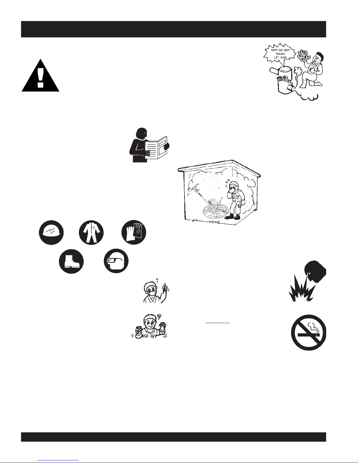
Safety Message Alert Symbols .............................. 8-9
Rules For Safe Operation .................................. 10-11
Operation And Safety Decals .................................. 12
Specifications (Trowel) ............................................ 13
Specifications (Engines).......................................... 14
Specifications (Trowel Weights) .............................. 14
General Information ................................................ 15
SCT SERIESTROWEL
Controls and Components ...................................... 16
Basic Engine ........................................................... 17
Assembly and Installation .................................. 18-19
Pre-Inspection .................................................... 20-21
Initial Start-Up (Gasoline Engine) ......................22-23
Operation ................................................................ 24
Options .................................................................... 25
Maintenance (Engine)........................................ 26-27
Maintenance (Trowel)) ....................................... 28-32
Troubleshooting (Trowel) ................................... 33-34
Troubleshooting (Engine) ................................... 34-35
Explanation of Codes in Remarks Column ............. 36
Suggested Spare Parts ........................................... 37
Decal Locator ..................................................... 38-39
Standard Handle Assembly ............................... 40-41
4-Blade Spider Assembly ................................... 42-43
Gearbox Assembly ............................................. 44-45
Guard Ring Assembly ........................................ 46-47
Stabilizer Ring Assembly ................................... 48-49
Engines Assembly .............................................. 50-51
Blades & Adjustment Fixture Assembly. ............ 52-53
HONDA GX160K1QX2ENGINE
Air Cleaner Assy. ................................................ 54-55
Camshaft Assy. .................................................. 56-57
Carburetor Assy. ................................................ 58-59
Control Assy. ...................................................... 60-61
Crankcase Cover Assy. ...................................... 62-63
Crankshaft Assy. ................................................ 64-65
Cylinder Barrel Assy. .......................................... 66-67
Cylinder Head Assy. ........................................... 68-69
Fan Cover Assy. ................................................. 70-71
Flywheel Assy..................................................... 72-73
Fuel Tank Asssembly ......................................... 74-75
Ignition Coil Asssembly ...................................... 76-77
Muffler Asssembly .............................................. 78-79
Piston Asssembly ............................................... 80-81
Recoil Starter Asssembly ................................... 82-83
Gaskets ................................................................... 85
Engine Labels .................................................... 86-87
HONDA GX240K1QA2ENGINE
Air Cleaner Asssembly ....................................... 88-89
Camshaft Asssembly ......................................... 90-91
Carburetor Asssembly ....................................... 92-93
Control Asssembly ............................................. 94-95
Crankcase Cover Asssembly ............................. 96-97
Crankshaft Asssembly ....................................... 98-99
Cylinder Barrel Asssembly .............................100-101
Cylinder Head Asssembly .............................. 102-103
Fan Cover Asssembly .................................... 104-105
Flywheel Asssembly ....................................... 106-107
Fuel Tank Asssembly ..................................... 108-109
Ignition Coil Asssembly ..................................110-111
Muffler Asssembly .......................................... 112-113
Piston Asssembly ........................................... 114-115
Recoil Starter Asssembly ............................... 116-117
Engine Labels ................................................ 118-119
Honda GX340K1QAP2 Engine
Air Cleaner Assembly..................................... 120-121
Camshaft Assembly ....................................... 122-123
Carburetor Assembly ..................................... 124-125
Crankcase Cover Assembly ........................... 126-127
Control Assembly ........................................... 128-129
Cylinder Barrel Assembly ............................... 130-131
Cylinder Head Assembly ................................ 132-133
Crankshaft Assembly ..................................... 134-135
Fan Cover Assembly ...................................... 136-137
Flywheel Assembly ........................................ 138-139
Fuel Tank Assembly ....................................... 140-141
Ignition Coil Assembly .................................... 142-143
Muffler Assembly ........................................... 144-145
Piston Assembly ............................................. 146-147
Recoil Starter Assembly................................. 148-149
Engine Labels ................................................ 150-151
Terms and Conditions of Sale Parts ..................... 152

SCT SERIES WALK-BEHIND TROWEL — PARTS & OPERATION MANUAL — REV. #3 (03/30/05) — PAGE 5
SCT SERIES TROWEL— PARTS ORDERING PROCEDURES
Get special freight allowances
when you order 10 or more
line items via FAX!**
■■
■■
■
UPS Ground Service at no charge for freight
■■
■■
■
UPS Third Day Service at one-half of actual freight
cost
No other allowances on freight shipped by any other carrier.
**Common nuts, bolts and washers (all items under $1.00 list price)
do not count towards the 10+ line items.
*DISCOUNTS ARE SUBJECT TO CHANGE*
Fax order discount and UPS special programs revised June 1, 1995
Earn Extra Discounts when
you order by FAX!
All parts orders which include complete part numbers
and are received by fax qualify for the following extra
discounts:
Number of
line items ordered Additional Discount
1-9 items 3%
10+ items** 5%
Now! Direct TOLL-FREE access
to our Parts Department!
Toll-free nationwide:
800-421-1244
Toll-free FAX:
800/6-PARTS-7 • 800-672-7877
■■
■■
■Dealer account number
■■
■■
■Dealer name and address
■■
■■
■Shipping address (if different than billing address)
■■
■■
■Return fax number
■■
■■
■Applicable model number
■■
■■
■Quantity, part number and description of each part
■■
■■
■Specify preferred method of shipment:
•UPS Ground
•UPS Second Day or Third Day*
•UPS Next Day*
•Federal Express Priority One (please provide us with your Federal
Express account number)*
•Airborne Express*
•Truck or parcel post
*Normally shipped the same day the order is received, if prior to 2PM west coast time.
Extra Fax DiscountExtra Fax Discount
Extra Fax Discount
for Domestic USAfor Domestic USA
for Domestic USA
Dealers OnlyDealers Only
Dealers Only

PAGE 6 — SCT SERIES WALK-BEHIND TROWEL— PARTS & OPERATION MANUAL — REV. #3 (03/30/05)
TRAINING CHECKLIST
This checklist will lists some of the minimum requirements for
machine maintenance and operation. Please feel free to detach
it and make copies. Use this checklist whenever a new operator
is to be trained or it can be used as a review for more experienced
operator’s.
Operator _________________________________________ Trainee __________________________________________
COMMENTS:
SCT SERIESTROWEL—TRAINING CHECKLIST
TSILKCEHCGNINIART
.ON NOITPIRCSED ?KO ETAD
1 .yletelpmoclaunaMs’rotarepOdaeR
2dnaenignefognikcehc,stnenopmocfonoitacol,tuoyalenihcaM
.leveldiulfxobraeg
3 .erudecorpgnileufer,metsysleuF
4 .)gninnurtonenihcam(slortnocfonoitarepO
5 .noitarepohctiwspotsytefas,slortnocytefaS
6 .serudecorppotsycnegremE
7 .enihcamfoputratS
8 .gnirevuenaM
9 .gnihctiP
01 .seuqinhcetgnihsinifetercnoC
11 .enihcamfonwodtuhS
21 .enihcamfognitfiL
31 .egarotsdnatropsnartenihcaM

SCT SERIES WALK-BEHIND TROWEL — PARTS & OPERATION MANUAL — REV. #3 (03/30/05) — PAGE 7
DAILY PRE-OPERATION CHECKLIST
COMMENTS:
SCT SERIESTROWEL— DAILY PRE-OPERATION CHECKLIST
TSILKCEHCNOITAREPO-ERPYLIAD
1 .leveLliOenignE
2 .leveLdiulFxobraeG
3 .sedalBfonoitidnoC
4 .noitarepOhctiPedalB
5 .noitarepOhctiwSpotSytefaS

PAGE 8 — SCT SERIES WALK-BEHIND TROWEL— PARTS & OPERATION MANUAL — REV. #3 (03/30/05)
SCT SERIES TROWEL— SAFETY MESSAGE ALERT SYMBOLS
Safety precautions should be followed at all times when operating
this equipment. Failure to read and understand the Safety
Messages and Operating Instructions could result in injury to
yourself and others.
FOR YOUR SAFETY AND THE SAFETY OF OTHERS!
This Owner's Manual has been developed to provide
complete instructions for the safe and efficient operation
of the SCT SERIESWALK-BEHIND TROWEL. For
engine maintenance information, please refer to the
engine manufacturers instructions for data relative to its
safe operation.
Before using this WALK-BEHIND TROWEL, ensure
that the operating individual has read and
understands all instructions in this manual.
NOTE
SAFETY MESSAGE ALERT SYMBOLS
The three (3) Safety Messages shown below will inform you
about potential hazards that could injure you or others. The
Safety Messages specifically address the level of exposure to
the operator, and are preceded by one of three words: DANGER,
WARNING, or CAUTION.
DANGER: You WILL be KILLED or
SERIOUSLY injured if you DO NOT follow
directions.
WARNING: You CAN be KILLED or
SERIOUSLY injured if you DO NOT follow
directions.
CAUTION: You CAN be injured if you
DO NOT follow directions.
HAZARD SYMBOLS
Engine exhaust gases contain poisonous
carbon monoxide. This gas is colorless and
odorless, and can cause death if inhaled.
NEVER operate this equipment in a confined
area or enclosed structure that does not
provide ample free flow air.
Potential hazards associated with trowel operation will be
referenced with "
Hazard Symbols
" which appear throughout
this manual, and will be referenced in conjunction with Safety
"
Message Alert Symbols
".
Gasoline is extremely flammable, and its
vapors can cause an explosion if ignited. DO
NOT start the engine near spilled fuel or
combustible fluids. DO NOT fill the fuel tank
while the engine is running or hot. DO NOT
overfill tank, since spilled fuel could ignite if it
comes into contact with hot engine parts or
sparks from the ignition system. Store fuel in
approved containers, in well-ventilated areas
and away from sparks and flames. NEVER
use fuel as a cleaning agent.
Burn Hazards
Engine components can generate extreme
heat. To prevent burns, DO NOT touch these
areas while the engine is running or
immediately after operations. NEVER
operate the engine with heat shields or heat
guards removed.
Rotating Parts
NEVER operate equipment with covers, or
guards removed. Keep fingers,
hands
,
hair
and
clothing
away from all moving parts to
prevent injury.
Explosive Fuel
Lethal Exhaust Gases

SCT SERIES WALK-BEHIND TROWEL — PARTS & OPERATION MANUAL — REV. #3 (03/30/05) — PAGE 9
Accidental Starting
ALWAYS place the engine ON/OFF switch
in the OFF position, when the trowel is not
in use.
Over Speed Conditions
NEVER tamper with the factory settings of the
engine governor or settings. Personal injury
and damage to the engine or equipment can
result if operating in speed ranges above
maximum allowable.
Respiratory Hazard
ALWAYS wear approved respiratory
protection.
ALWAYS wear approved eye and hearing
protection.
Sight and Hearing hazard
Equipment Damage Messages
Other important messages are provided throughout this manual
to help prevent damage to your trowel, other property, or the
surrounding environment.
SCT SERIES TROWEL— SAFETY MESSAGE ALERT SYMBOLS
This
walk-behind trowel
, other
property, or the surrounding
environment could be damaged if
you do not follow instructions.
NOTE

PAGE 10 — SCT SERIES WALK-BEHIND TROWEL— PARTS & OPERATION MANUAL — REV. #3 (03/30/05)
CAUTION:
Failure to follow instructions in this manual may
lead to serious injury or even death! This
equipment is to be operated by trained and
qualified personnel only! This equipment is
for industrial use only.
The following safety guidelines should always be used when
operating the SCT SERIESwalk-behind trowel.
SAFETY
■
DO NOT operate or service this equipment
before reading this entire manual.
■
This equipment should not be operated by persons under 18
years of age.
■
NEVER operate the trowel without proper protective clothing,
shatterproof glasses, steel-toed boots and other protective
devices required by the job.
■
NEVER operate this equipment when not feeling
well due to fatigue, illness or taking medicine.
■
NEVER operate the trowel under the
influence or drugs or alcohol.
■
NEVER use accessories or attachments, which are not
recommended by SCT SERIESfor this equipment. Damage
to the equipment and/or injury to user may result.
■
Manufacture does not assume responsibility for any accident
due to equipment modifications.
■
Whenever necessary, replace nameplate, operation and
safety decals when they become difficult to read.
■
ALWAYS check the trowel for loosened screws, nuts, or bolts
before starting.
■
ALWAYS use extreme caution when
working with flammable liquids. When
refueling, stop the engine and allow it to
cool.
■
NEVER
smoke
around or near the
machine. Fire or explosion could result from
fuel vapors
, or if fuel is spilled on a
hot!
engine.
■
NEVER operate the trowel in an explosive atmosphere or
near combustible materials. An explosion or fire could result
causing severe
bodily harm or even death.
■
Topping-off the fuel tank filler port is dangerous, as it tends to
spill fuel.
■
NEVER touch the hot exhaust
manifold, muffler or cylinder.Allow
these parts to cool before
servicing the trowel.
■
The engine of this trowel requires an adequate free flow of
cooling air. NEVER operate the trowel in any enclosed or
narrow area where free flow
of the air is restricted. If the
air flow is restricted it will
cause serious damage to
the trowel's engine and
may cause injury to people.
Remember the trowel's
engine gives off
DEADLY
carbon monoxide gas.
■
HighTemperatures – Allow the engine to cool before adding
fuel or performing service and maintenance functions. Contact
with
hot!
components can cause serious burns.
■
ALWAYS refuel in a well-ventilated area, away from sparks
and open flames.
SCT SERIES TROWEL — RULES FOR SAFE OPERATION

SCT SERIES WALK-BEHIND TROWEL — PARTS & OPERATION MANUAL — REV. #3 (03/30/05) — PAGE 11
SCT SERIES TROWEL — RULES FOR SAFE OPERATION
■
DO NOT operate this trowel unless all guards and safety
devices are attached and in place. See Pages 16 and 17.
■
ALWAYS use proper lifting techniques when moving the
trowel.
■
ALWAYS check to make sure that the operating area is clear
before starting the engine.
■
ALWAYS test the safety
safety stop switch
devices before
operating the trowel.
■
NEVER place your
feet
or
hands
inside the guard rings
while starting or operating this equipment.
■
AVOID wearing jewelry or loose fitting clothing that may snag
on the controls or moving parts, this can cause a serious
injury.
■
ALWAYS keep clear of
rotating
or
moving parts
while
operating the trowel.
■
NEVER leave the machine
unattended
while running.
■
Moving Parts – Shut down the engine before performing
service or maintenance functions. Contact with moving parts
can cause serious injury.
Maintenance Safety
■
Disconnect the spark plug wires before attempting any type
of service.
■
Securely support any machine components that must be
raised.
■
NEVER lubricate components or attempt service on a running
machine.
■
DO NOT use food or plastic containers to dispose of
hazardous waste.
■
DO NOT pour
waste
,
oil
or
fuel
directly onto the ground,
down a drain or into any water source.
CAUTIONCAUTION
CAUTIONCAUTION
CAUTION
Emergencies
■
ALWAYS know the location of the nearest
fire extinguisher
and
first aid kit
. Know
the location of the nearest telephone. Also
know the phone numbers of the nearest
ambulance
,
doctor
and
fire department
.
This information will be invaluable in the
case of an
emergency
.
■
Keep the trowel in proper running condition.
■
Make sure that there is no buildup of concrete, grease, oil or
debris on the trowel.
■
Fix damage to the trowel immediately and always replace
broken parts.
■
Dispose of hazardous waste properly. Examples of potentially
hazardous waste are used
motor oil
,
fuel
and
fuel filters
.
■
High Temperatures – Allow the machine and engine to
cool
before adding fuel or performing service and
maintenance functions. Contact with
hot!
components can
cause serious burns.

PAGE 12 — SCT SERIES WALK-BEHIND TROWEL— PARTS & OPERATION MANUAL — REV. #3 (03/30/05)
SCT SERIES TROWEL — OPERATION AND SAFETY DECALS
Machine Safety Decals
The SCT SERIESwalk-behind trowel is equipped with a number of safety decals.These decals are provided for operator safety and
maintenance information. Figure 1 below illustrates these decals as they appear on the machine. Should any of these decals
become unreadable, replacements can be obtained from your dealer.
Figure 1. SCT SERIESTrowel Decals

SCT SERIES WALK-BEHIND TROWEL — PARTS & OPERATION MANUAL — REV. #3 (03/30/05) — PAGE 13
SCT SERIES TROWEL — SPECIFICATIONS (TROWEL)
NOTE:
1. Sound pressure is a weighted measure. Measured at the
operators ear position while the walk-behind trowel is
operating at full throttle on concrete in a manner most often
experienced in “
normal
” circumstances. Sound pressure
may vary depending upon the condition of the concrete.
Hearing protection is always recommended.
Figure 2. SCT SERIESTrowel Dimensions
2. The vibration level indicated is the maximum RMS (Root
Mean Square) value obtained at the handle grip while
operating the walk-behind trowel on curing concrete in a
manner most often experienced in “
normal
” circumstances.
Values were obtained from all three axes of motion. The
values shown represent the maximum RMS value from
these measurements.
Side View
Top View
snoitacificepSleworTWOTS.1elbaT
LEDOM 63TCS 64TCS
)kooHgnitfiL(thgieH–A )mm6.139(.ni7.63 )mm2.678(.ni5.43
)reveLtnemegagnEthgieH–B )mm2.440,1(.ni4.14 )mm2.440,1(.ni1.14
htdiW–C )mm1.729(.ni5.63 )mm4.861,1(.ni0.64
htgneL–D )mm4.987,1(.ni5.07 )mm1.019,1(.ni2.57
gnitarepO–thgieW 3ELBATEES
erusserPdnuoS
1
bd49 bd79
noitarbiV
2
s/m6.91(g0.2
2
) s/m5.42(g5.2
2
)
retemaiDgniR )mc7.29(.ni5.63 )mc711(.ni64
sedalBforebmuN 4 4
)s/m(MPF–deepSpiTedalB )s/m5.6(mpf092,1 )s/m5.6(mpf092,1
)enilosaG(MPR–rotoR mpr0083@441 mpr0083@441
)mc(.ni–htdiWhtaP )mc44.19(.ni63 )48.611(.ni64

PAGE 14 — SCT SERIES WALK-BEHIND TROWEL— PARTS & OPERATION MANUAL — REV. #3 (03/30/05)
SCT SERIESTROWEL— SPECIFICATIONS (ENGINES)
)sthgieWleworT(snoitacificepS.3elbaT
LEDOMECRUOSREWOP THGIEWGNITAREPO
)eldnahhtiw( THGIEWGNIPPIHS
55H63TCSadnoHPH5.5)gK78(.sbl091)gK501(.sbl032
08H
63TCSadnoHPH8)gK79(.sbl412)gK611(.sbl452
08H64TCSadnoHPH8)gK011(.sbl242)gK331(.sbl292
11H64TCSadnoHPH11)gK431(.
sbl592)gK161(.sbl553
)senignE(snoitacificepS.2elbaT
ledoM2XQ061XGADNOH2AQ1K042XGADNOH2PAQ1K043XGADNOH
epyT
elgniS,ekorts4delooc-riA
tfahSlatnoziroH,VHO,rednilyC
enignEenilosaG
elgniS,ekorts4delooc-riA
tfahSlatnoziroH,VHO,rednilyC
enignEenilosaG
elgniS,ekorts4delooc
-riA
tfahSlatnoziroH,VHO,rednilyC
enignEenilosaG
ekortSXeroB .ni8.1x.ni7.2
)mm54xmm86(
.ni3.2x.ni9.2
)mm85xm
m37(
.ni5.2x.ni2.3
)mm46xmm28(
tnemecalpsiD)cc361(.ni-uc9.9)cc242(.ni-uc18.41)cc733(.ni-uc6.02
tuptuOxaM.M.P.
R0004/.P.H5.5.M.P.R0063/.P.H0.8.M.P.R0063/.P.H0.11
yticapaCknaTleuF)sretil6.3(.lag.S.U59.0)sretil6(.lag.S.
U95.1)sretil5.6(lag.S.U27.1
leuFenilosaGelibomotuAdedaelnUenilosaGelibomotuAdedaelnUenilosaGelibomotuAdeda
elnU
yticapaCliOebuL)retil06.0(.tq.S.U36.0)sretil1.1(.tq.S.U61.1)sretil1.1(.tq.S.U61.1
lortnoCdeepS
dohteM e
pyTthgiew-ylFlagufirtneCepyTthgiew-ylFlagufirtneCepyTthgiew-ylFlagufirtneC
dohteMgnitratStratSlioceRtratSl
ioceRtratSlioceR
noisnemiD
)HxWxL(
.ni2.31x3.41x0.21
)mm533x263x403(
.ni1.61x9.61x0.41
)mm014x034x553(
4.71x7
.71x0.51
)mm344x054x083(
thgieWteNyrD)gK0.51(.sbl1.33)gK52(.sbl1.55)gK13(.sbl4.86

SCT SERIES WALK-BEHIND TROWEL — PARTS & OPERATION MANUAL — REV. #3 (03/30/05) — PAGE 15
SCT SERIESTROWEL— GENERAL INFORMATION
SCT SERIESWalk-BehindTrowel Familiarization
This walk-behind trowel is designed for the
floating
and
finishing
of concrete slabs.
Take a walk around the trowel. Take notice of all the major
components (see Figure 3, pages 16 and 17) like the engine,
blades, quick adjust control, (on those equiped models), air
cleaner, centrifugal stop switch etc. Check that there is always
oil in the engine.
Read
all the safety instructions carefully. Safety instructions will
be found throughout this manual and on the trowel. Keep all
safety information in good, readable condition. Operators should
be well trained on the operation and maintenance of the trowel.
Before using your trowel, test it on a flat watered down section of
finished concrete that is free of any debris and other objects.
This trial test run will increase your confidence in using the trowel
and at the same time it will familiarize you with the trowel’s
controls. In addition you will understand how the trowel handles
under actual conditions.
Engines
The 36" trowel is available with a 5.5 HP HONDA or an 8.0 HP
HONDA gasoline engine while the 46" trowel is available with
an 8.0 HP HONDA or an 11.0 HP HONDA gasoline engine.
Refer to the engine owner’s manual for instructions regarding
the operation and maintenance of your engine. The engine
manual is included with your trowel at the time of shipment.
Please contact your nearest Multiquip Dealer for a replacement
should the original manual disappear or become unusable.
Drive System
Power is transferred from the engine to the gearbox input shaft
via a V-belt or pulley drive system.The pulley engages using a
centrifugal clutch.
Gearbox
The
gearbox
is located beneath the engine and transfers power
to the
rotor
or
spider
assembly. The gearbox controls the
rotational speed of the trowel and is equipped with two shafts
(input and output).
Spider
The vertical output shaft of the gearbox connects to a cast hub
called the
spider
. The spider has 4 arms that extend outward
that are used for attachment of blades or other accessories.
Remember as the gearbox output shaft rotates so does the spider
assembly.
Moving the SCT SERIESWalk-Behind Trowel
This walk-behind trowel is designed to be moved and handled
in several ways. One way to lift the trowel is to use an
optional
lifting tube
. See page 24, Figure 20. When using the lifting
tube, always use
two persons
to lift the trowel.
These models have a
lifting bail
installed so strap or chain can
be attached, allowing a forklift or crane to lift the trowel up onto a
slab of concrete. Use a lifting device of adequate lifting capacity
to lift the trowel.
Training
For proper training, please use the “TRAINING CHECKLIST”
located in the front of this manual (Page 6). This checklist will
provide an outline for an experienced operator to provide training
to a new operator.
CAUTIONCAUTION
CAUTIONCAUTION
CAUTION
Blades
The blades of the trowel finish the concrete as they are rotated
around the surface. Blades are classified as
combination
(8 inches wide),
float
(10 or 8 inches wide), and finish (6
inches wide). This trowel comes equipped with four blades
per rotor equally spaced in a radial pattern and attached to
vertical rotating shaft by means of a
spider assembly.
Centrifugal Stop Switch
In the event of a trowel runaway condition, (operator releases
the handle), a
centrifugal stop switch
will stop the engine
and bring the trowel to a halt.
NEVER attempt to
lift
the trowel by yourself.
ALWAYS get the assistance of another
person to help lift the trowel or use a crane
or lifting device to move the trowel.

PAGE 16 — SCT SERIES WALK-BEHIND TROWEL— PARTS & OPERATION MANUAL — REV. #3 (03/30/05)
SCT SERIES TROWEL— CONTROLS AND COMPONENTS
Figure 3. SCT SERIESWalk-Behind Trowels
Figures 3 shows the location of the basic controls or components,
for the SCT SERIEStrowel. Listed below is a brief explanation of
each control or component
1. Pitch Control - Turn this "Star Wheel" clockwise for increase
blade pitch, and counter-clockwise for decrease blade pitch
2. Hand Grip/Handle Bar – When operating the trowel, place
both hands on each grip to maneuver the trowel. Replace
hand grips when they become worn or damaged.
3. Throttle – Controls engine speed.
4. Engine – This trowel uses a Honda gasoline engine.
5. Centrifugal Safety Stop Switch – In the event the operator
loses control of the trowel, this switch will shut-down the
engine.
6. Trowel Lifting Point – Use a hoist, forklift, or other suitable
lifting device to lift the trowel on and off the concrete slab.
7. Engine ON-OFF Switch– Turn to the "ON" position for
starting the engine and to the "OFF" position to prevent the
engine from starting.
8. MainTube - Houses throttle control and pitch cables.
9. Guard Ring- NEVER! put hands or feet inside guard ring.
10. V-Belt Cover – Remove this cover to gain access to the V-
belt. NEVER operate the trowel with this cover removed.
11. Trowel Arm – NEVER operate the trowel with a bent, broken
or out of adjustment trowel arm. If the blades show uneven
wear patterns or some blades wear out faster than others,
the trowel arm may need to be adjusted. Use the trowel
arm adjustment tool P/N 1817 to adjust the trowel arms.
12. Blades – This trowel is equipped with combination blades.
These blades are versatile and should take care of most
troweling needs. In addition float discs can be attached to
the trowel arms that will allow the trowel to float on "wet"
concrete.
13. Stabilizer Ring – Reduces trowel arm vibration. Helps
stabilize trowel arm.

SCT SERIES WALK-BEHIND TROWEL — PARTS & OPERATION MANUAL — REV. #3 (03/30/05) — PAGE 17
Figure 4. Engine Controls and Components
INITIAL SERVICING (ENGINE)
The engine (Figure 4) must be checked for proper lubrication and
filled with fuel prior to operation. Refer to the manufacturers engine
manual for instructions & details of operation and servicing.
1. Fuel Filler Cap – Remove this cap to add unleaded
gasoline to the fuel tank. Make sure cap is tightened
securely. DO NOT over fill.
5. Fuel Valve Lever – OPEN to let fuel flow, CLOSE to stop
the flow of fuel.
6. Choke Lever – Used in the starting of a cold engine, or in
cold weather conditions. The choke enriches the fuel
mixture.
7. Air Cleaner – Prevents dirt and other debris from entering
the air intake system. Remove wing-nut on top of air filter
cannister to gain access to filter element.
8. Spark Plug – Provides spark to the ignition system. Set
spark plug gap to 0.6 - 0.7 mm (0.028 - 0.031 inch) Clean
spark plug once a week.
9. Muffler – Used to reduce noise and emissions.
Engine components can generate extreme heat.
To prevent burns, DO NOT touch these areas
while the engine is running or immediately after
operating. NEVER operate the engine with the
muffler removed.
10. Fuel Tank – Holds unleaded gasoline. For additional
information refer to engine owner's manual.
DANGER
WARNING
SCT SERIESTROWEL— BASIC ENGINE
Adding fuel to the tank should be done only when
the engine is stopped and has had an opportunity
to cool down. In the event of a fuel spill, DO NOT
attempt to start the engine until the fuel residue has been completely
wiped up, and the area surrounding the engine is dry.
2. Throttle Lever – Used to adjust engine RPM speed (lever
advanced forward
SLOW
, lever back toward operator
FAST
).
3. Engine ON/OFF Switch – ON position permits engine
starting, OFF position stops engine operations.
4. Recoil Starter (pull rope) – Manual-starting method. Pull
the starter grip until resistance is felt, then pull briskly and
smoothly.
Operating the engine without an air
filter, with a damaged air filter, or a
filter in need of replacement will
allow dirt to enter the engine, causing
rapid engine wear
NOTE

PAGE 18 — SCT SERIES WALK-BEHIND TROWEL— PARTS & OPERATION MANUAL — REV. #3 (03/30/05)
3. Tighten cable clamp screw.
4. After the cable has been installed on the engine, work the
throttle lever to verify the throttle cable is at the proper
length. Adjust the cable as necessary.
5. Reinstall the air cleaner housing if previously removed.
SCT SERIESTROWEL — ASSEMBLY AND INSTALLATION
Assembly and Installation
Before the trowel can be put into operation there are some
components that must be installed before the trowel can be used.
This section provided general instructions on how to install those
components.
Handle Tube Installation
1. Install the
handle tube
to the gearbox as shown in (Figure 5).
The mounting hardware should be contained in the shipping
container.
Figure 5. Handle Tube Installation
2. Connect the throttle cable to the engine. (Figure 7). (The air
cleaner housing may have to be removed to provide access
for throttle cable installation.) When connecting the cable
housing, make sure that no more than
1/4" (6.4mm)
of the
cable housing protrudes past the housing clamp on the
engine.
Figure 7. Throttle Cable Connection
Figure 6. Throttle
Throttle Cable Installation
1. Set the
throttle
(Figure 6) to the idle position (lever away
from the operator).

SCT SERIES WALK-BEHIND TROWEL — PARTS & OPERATION MANUAL — REV. #3 (03/30/05) — PAGE 19
SCT SERIESTROWEL — ASSEMBLY AND INSTALLATION
Figure 11. Cable Yoke Attachment
5. Using a wrench, tighten the second brass set nut up against
the yoke boss.This will lock the cable in place.
6. Use a wrench and finish tightening the first brass set nut up
against the yoke boss.
2. Remove one brass set nut from the blade pitch cable end
as shown in (Figure 10).
3. Thread the second brass set nut towards the cable as far
as possible.
4. Insert the cable end through the yoke eyelet (Figure 11)
Tighten the first brass set nut by hand to remove all the
slack from the cable.
Figure 10. Blade Pitch Cable
Safety Stop Wire
Locate the
SAFETY STOP
wire protruding from the handle tube
(Figure 8) and connect it to the
tail wire on the engine.Test the
safety stop switch to insure proper operation.
Figure 8. Engine Safety Stop Wire Connection
Figure 9. "No Pitch" Position
1. Expose the pitch cable to maximum by adjusting the handle
pitch to the "no pitch" position. On the standard model turn
the pitch control counter-clockwise, (Figure 9).
Pitch Cable Installation
YOKE
THREAD CABLE END
THROUGH YOKE EYELET
TIGHTEN SECOND
BRASS SET NUT
AGAINST YOKE BOSS USE A WRENCH TO
TIGHTEN FIRST BRASS
SET NUT AGAINST YOKE BOSS

PAGE 20 — SCT SERIES WALK-BEHIND TROWEL— PARTS & OPERATION MANUAL — REV. #3 (03/30/05)
CAUTIONCAUTION
CAUTIONCAUTION
CAUTION
NEVER operate the trowel
in a confined area or
enclosed area structure
that does not provide
ample
free flow of air
.
ALWAYS wear approved eye and hearing
protection before operating the trowel.
NEVER place hands or feet inside the guard
rings while the engine is running. ALWAYS
shut the engine down before performing any
kind of maintenance service on the trowel.
SCT SERIESTROWEL— PRE-INSPECTION
It is recommended that the trowel's
safety stop switch
is used
to stop the engine after every use. Doing this will verify that the
switch is working properly and presents no danger to the operator.
Before Starting
1. Read safety instructions at the beginning of manual.
2. Clean the
trowel
, removing dirt and dust, particularly the air
filter and carburetor.
3. Check the air filter for dirt and dust. If air filter is dirty, replace
air filter with a new one as required.
4. Check carburetor for external dirt and dust. Clean with dry
compressed air.
5. Check fastening nuts and bolts for tightness.
Engine Oil Check
1. To check the engine oil level, place the trowel on secure level
ground with the engine stopped.
2. Remove the filler dipstick from the engine oil filler hole
(Figure 12) and wipe it clean.
Figure 12. Engine Oil Dipstick (Removal)
3. Insert and remove the dipstick without screwing itinto thefiller
neck. Check the oil level shown on the dipstick.
4. If the oil level is low (Figure 13), fill to the edge of the oil filler
hole with the recommended oil type (Table 4). Maximum oil
capacity is 400 cc.
Figure 13. Engine Oil Dipstick (Oil Level)
Reference manufacturer engine
manual for specific servicing
instructions.
NOTE
epyTliO.4elbaT
nosaeS erutarepmeT epyTliO
remmuS rehgiHroC°52 03-W01EAS
llaF/gnirpS C°01~C°52 02/03-W01EAS
retniW rewoLroC°0 01-W01EAS
This manual suits for next models
1
Table of contents
Other Stow Trowel manuals