strada Aquatherm STA140UC User manual

0
Technical Manual
Manual must be completed by Installer and left with Home Owner

28/03/19
1
Contents
Aquatherm: Schematic ........................................................................................2
Aquatherm: Connection Heights .........................................................................3
Technical Data .....................................................................................................3
Handling & Storage..............................................................................................4
Mains Water Supply ............................................................................................4
Discharge/Overflow Requirements .....................................................................4
Water Treatment.................................................................................................5
Commissioning.....................................................................................................6
Immersion Heaters ..............................................................................................8
Troubleshooting...................................................................................................9
Aquatherm Spares List.......................................................................................11
Commissioning Checklist ...................................................................................12

28/03/19
2
Aquatherm: Schematic
Immersion Heater
3kW
Drain
Cold Mains
Secondary Water
c/w Y Strainer
Hot Out
c/w Thermostatic
Mixing Valve
Boiler Coil
Return
High Efficiency
Secondary Coil
Ballvalve
Boiler
Control Stat
@75⁰C
Central
Heating Flow
& Return
Boiler Flow
Boiler Return
Boiler Coil Flow

28/03/19
3
Aquatherm: Connection Heights
The connection heights shown below are taken from the ground (in mm).
Allow an additional 100mm to the diameter for external pipework connections.
Capacity (Litres)
140
160
180
210
Height
1250
1475
1500
1700
Diameter
570
570
570
570
Drain
95
95
95
95
Immersion Heater
160
160
160
160
Central Heating Flow
450
550
550
650
Central Heating Return
105
105
105
105
Boiler Flow
850
1075
1100
1300
Boiler Return
105
105
105
105
Boiler Coil Flow
555
555
555
555
Boiler Coil Return
105
105
105
105
Control Stat
340
300
300
350
Hot Out (Coil)
850
1075
1100
1300
Cold In (Coil)
350
495
520
720
Ballvalve
1180
1405
1430
1630
Technical Data
ERP / Heat Loss Data
Capacity (Litres)
140
160
180
210
Insulation Thickness (mm)
60
60
60
60
ERP Class
C
C
C
C
Standing Heat Loss (Watts)
74
78
82
87
Standing Heat Loss (kWh/day)
1.78
1.87
1.97
2.09
Tested in accordance with HWA Thermal Store Specification

28/03/19
4
Handling & Storage
DO NOT LIFT BY THE PIPEWORK as this can loosen off the pre-tested pipework
and may result in leaks.
Check the joints before filling with water in case anything has been loosened
in transit.
Any manual lifting will need to comply with the requirements of the Manual
Handling Operations Regulations issued by the Health & Safety Executive.
For installations on higher levels of properties such as the 4th floor it is
recommended move the tank vertically within a lift.
Mains Water Supply
The mains supply to the unit should ideally be in a minimum of 22mm diameter
but will work with 15mm if there is adequate pressure and flow rate.
Minimum incoming mains pressure of 1.0 Bar and a minimum flow rate of 20
Litres/minute.Careful consideration should be made to ensure the pressure of
hot and cold supplies are balanced.
An incoming pressure of 2.1 Bar is the most optimal for performance.
If the incoming pressure exceeds 3 Bar, then a pressure reducing valve must be
fitted after the stopcock of where the incoming cold supply enters the property.
No Pressure Reducing Valve or Check Valve should be fitted within 2 metres of
the Cold Inlet to the tank.
If the flow rate exceeds 18 Litres per minute at any tap, it should be restricted
to maintain the performance of the system as a whole.
Discharge/Overflow Requirements
The Aquatherm is a Vented Thermal Store and therefore does not require safety
discharge from a Pressure and Temperature Relief Valve as highlighted in Part G of the
Building Regulations.
The overflow should be run in either 22mm copper tube or high temperature overflow
pipe with suitable supports.

28/03/19
5
Water Treatment
In accordance with the Building Regulations L1A: New Dwellings/ L1B: Existing
Dwellings, the requirements set out in the Domestic Building Services Compliance
Guide specify that “where the mains water hardness exceeds 200ppm provision should
be made to treat the feed water to water heaters and the hot water circuit of
combination boilers to reduce the rate of accumulation of lime scale”. In most instances
of this water condition, an inline Water Conditioner/Scale Inhibitor would be fitted to
the incoming mains.
The water quality shall be in accordance with European Council Directive 98/83/EC, or
revised version at the date of installation, and is not fed with water from a private
supply. Particular:
Chloride content: Max. 200 mg/l
Sulphate content: Max. 200 mg/l
Combination chloride/sulphate: Max. 300 mg/l (in total)
The tank is part of the primary system and, along with other parts of the primary circuit,
will require the application of a protective scale and corrosion inhibitor such as Fernox
to ensure adequate protection. This should avoid having corrosive material in the
primary system and remove any build-up of sludge which can reduce the performance
of the High Efficiency Heat Exchanger Coil.
The volumes and concentration of inhibitor required should be calculated in accordance
with the manufacturer’s instructions. Please ensure that the thermal store volume is
also included as well as the radiator and pipework volume.
If there are doubts regarding the quality of water being used to fill the tank, an inhibitor
should be added to the appliance when filling in line with the manufacturer’s
instructions for these products.
Please note that the primary water within the thermal store water is used as primary
storage and the domestic hot water is heated instantaneously by means of the High
Efficiency Heat Exchanger Coil. Therefore, treating the primary water will not have an
effect on the domestic hot water supply.

28/03/19
6
Commissioning
The below is a recommended guide of actions and checks that should be undertaken
during commissioning:-
DO
During commissioning, complete all relevant sections of the Commissioning
Checklist (Page 10-12). This must be completed during commissioning and left
with product to meet the Warranty conditions.
Check the incoming mains water pressure. If the incoming mains pressure is higher
than 3.0 Bar, fit a Pressure Reducing Valve set at 3.0 Bar maximum –recommended
2.1 Bar where the cold supply enters the property as this will create balanced
pressure throughout.
Ensure that connections are fitted in accordance with the sketch supplied
Ensure the drain is connected to allow draining of the unit if required. If a drain-
cock is fitted, we recommend a DZR fitting.
Fit the Overflow with Copper piping or high temperature plastic to the thermal
store system where required.
Ensure minimum of 225mm between the top of the tank and ceiling to allow access
to service the ball-valve if ever required.
Check that all pipework connections on the tank are tight with pipes fully inserted
following transit and handling.
Fill the tank via the ball-valve in the Feed & Expansion Tank.
Ensure the system is inhibited correctly –see page 6.
Check the water level in the Feed & Expansion Tank, and adjust ball-valve so water
is at lowest level.
On the Automatic Fill version, turn down servicing valve once system is initially filled
to where the warning/overflow pipe will cope with the discharge from a ball-valve
failure.
On the Manual Fill version, once the unit is filled through the pipework, close off
the isolation valve, disconnect the flexible hose from the pipework and cap the pipe
to avoid any dead legs.
Check for leaks throughout the thermal storage system.
Run all taps and other hot outlets to remove all air from the system.
Immersion Heaters should be set at 70⁰C.

28/03/19
7
Boilers –Set the boiler pump to its highest setting. Set the Boiler Thermostat and
also the tank thermostat to maximum. Fire the boiler on HOT WATER ONLY setting
and wait until the boiler goes off. Turn the cylinder thermostat down slowly till it
clicks off, then turn it down by approximately 2⁰C. This should mean that the tank
thermostat controls the system. This can be checked by running off some of the
hot water, re-firing the boiler and checking that the tank thermostat is in control.
Ensure the store temperature is set to 75⁰C (70⁰C minimum and 80⁰C maximum)
on the store temperature gauge. This can be increased but consideration should be
made for the temperature and pressure rise, caused by “creeping”, where small
draw offs are present.
On installs where central heating is run from the tank, ensure that 500mm height
difference is in place between the highest point of the radiator circuit and the
bottom of the Feed & Expansion Tank.
Ensure that all exposed pipework on the tank is insulated to minimalise any heat
losses.
Ensure the Thermostatic Mixing Valve is adjusted to control the hot water outlet
temperature between 50 - 55°C (take shower differential into consideration).
Check the boiler pump setting is set as high as possible without emitting excessive
noise to prevent a boiler temperature differential of greater than 11°C.
If required, chlorinate the hot and cold water system in accordance with BS 6700
and Water Regulations. Please note that the whole of the domestic hot and cold
water systems must be adequately flushed after chlorination. Failure to do so will
cause damage to the exchangers/immersion heaters etc.
DON’T
Use a combined feed and vent.
Use tube smaller than 28mm between boiler and tank if the boiler exceeds an
output of 60,000 Btu (17kW).
Place any clothing or other combustible materials against or on the tank.

28/03/19
8
Immersion Heaters
Immersion Heaters should be set to ensure the reading on the Thermometer
reaches 75°C (maximum 80°C) once the unit is heated.
We would recommend setting the Immersion Heaters at 70°C and the high
limit at 90°C. This can be lowered or increased as required for the installation
requirements.
If in any doubt of how to set the Immersion or what temperature we would
advise for specific installations, please contact us on 01592 611123.
All Immersion Heaters should be wired by a qualified electrician as shown
below;

28/03/19
9
Troubleshooting
SYMPTOM
SOLUTION
The water at the tap
is lukewarm or cold.
1) Check the thermometer is showing the store temperature is at
or approaching 75°C- 80C.
2) If this is not the case, ensure that the boiler is firing, that the
control thermostat is set at 75⁰C and allow sufficient time for the
store to reach working temperature
The thermal store is
at 75°C and the
water at the taps is
still lukewarm or cold
1) If the store is at or approaching 75°C - 80C, check that the
Thermostatic Mixing Valve is correctly set. The maximum
temperature of water from the Mixing Valve should be about
55C.
2) If the valve is correctly set, check that the flow rate at any outlet
(e.g. bath tap) does not exceed 18 Litres per minute. If the flow
rate is too high then sufficient heat transfer inside may not be
occurring.
Turn the flow through the tap down or fit a suitable flow
restrictor and the temperature will increase.
3) If Stage 1 and 2 has not resolved the problem a competent
installer should check the mixing valve for blockages within the
internal filter of the mixing valve.
Not enough hot
water and less than
75°C on the
thermometer.
Check the heat sources and their input in (kW) to the store as this will
be lower than the kW output which will result in the store not
producing enough heat for the exchanger to provide heated mains
pressure water.
There is a brownish
tint to the mains
pressure hot water.
This could be a symptom with the heat exchanger coil leaking inside
the thermal store. An installer should have this tested. If this is the
case, pay attention to the Feed & Expansion Tank as the pressure
within the store will increase causing the tank to overflow continually.

28/03/19
10
Tank is set at 75°C
but the mains
pressure
temperature drops
quickly when running
a tap (e.g. bath)
1) If an inhibitor has been installed, check with the installer that it
has been installed at the correct proportion and checked at
appropriate frequencies.
2) The in-line strainer in the cold mains supply to the unit may be
choked and require cleaning.
3) Carefully check the hot water temperature flow into the mixing
valve. If it is very hot, it may be that the valve needs to be
checked / replaced. A competent installer should check the
mixing valve for blockages within the internal filter.
4) If the DHW Coil is giving an initial heat transfer and then fading,
this could be a sign of scale build up inside the Heat Exchanger
Coil, especially if in a known hard water area. A competent
installer would need to descale the DHW coil and check/fit
descaling equipment.

28/03/19
11
Aquatherm Spares List
Part Number
Description
SUTMIX1
22mm Thermostatic Mixing Valve
SUTVESS1
2 Litre Expansion Vessel
SUTSTAT1
Cylinder Thermostat
SUTSTRAINER1
22mm Y-Strainer
SUTBALL1
15mm Ballvalve
SUTFLOAT1
4.5” Plastic Float

28/03/19
12
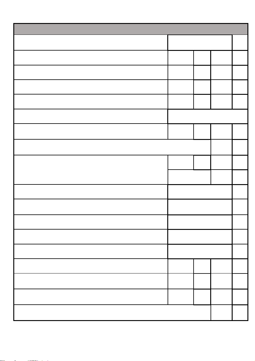
Commissioning Checklist
THERMAL STORE MAINS PRESSURE HOT WATER STORAGE SYSTEM
COMMISIONING CHECKLIST
This Commissioning Checklist is to be completed in full by the competent person who
commissioned the storage system as a means of demonstrating compliance with the
appropriate Building Regulations and then handed to the customer to keep for future
reference.
Failure to install and commission this equipment to the manufacturer’s instructions may
invalidate the warranty but does not affect statutory rights.
Customer Name:
Telephone Number:
Address:
Aquatherm Make & Model:
Production Number:
Commissioned by (PRINT NAME):
Company Name:
Telephone Number:
Company Address:
Commissioning Date:
28/03/19
13
ALL SYSTEMS
What is the incoming static cold water pressure at the inlet
to the system?
Bar
If above 3.0 Bar, has a pressure reducing valve been fitted?
Yes
No
Has cold mains strainer been cleaned of installation debris?
Yes
No
Is the installation in a hard water area (above 200ppm)?
Yes
No
If yes, has a water scale conditioner/inhibitor been fitted?
Yes
No
What type of scale conditioner/inhibitor has been fitted?
Has flow rate been restricted to a maximum of 18 litres at
any one outlet?
Yes
No
Time and temperature controls have been fitted in compliance with Part L of
the Building Regulations?
Yes
Type of control system (if applicable)
Y Plan
S Plan
Other
What is the hot water thermostat set temperature?
⁰C
If fitted, what is the Immersion Heater thermostat
temperature?
⁰C
What is the hot water temperature at the nearest outlet?
⁰C
What store temperature is the unit sitting at? (Max 80⁰C)
⁰C
What is the maximum hot water temperature at taps?
⁰C
Is the cylinder solar (or other renewables) compatible?
Yes
No
If a manual fill, has any ball-valve been disconnected or
blanked?
Yes
No
Has the automatic fill flow rate been reduced to ensure the
overflow can cope?
Yes
No
All appropriate pipes have been insulated up to 1 metre or the point where
they become concealed?
Yes

28/03/19
14
ALL SYSTEMS PRIMARY SETTINGS (Indirect Heating Only)
Is the primary circuit a sealed or open vented system?
Sealed
Open
What is the maximum primary flow temperature?
⁰C
ALL INSTALLATIONS
The hot water system complies with the appropriate Building Regulations.
Yes
The system has been installed and commissioned in accordance with the
manufacturer’s instructions.
Yes
The system controls have been demonstrated and understood by the
customer.
Yes
The manufacturer’s literature, including this Checklist, has been explained
and left with customer.
Yes
Commissioning Engineer’s Signature:
Customer’s Signature:
(To confirm satisfactory demonstration and receipt of manufacturer’s literature)

0


0
Advanced Water Company
Unit D5 Enterprise Way
Vale Park
Evesham
Worcestershire
WR11 1GS
Tel: 01386 760066
Fax: 01386 760077
Email: sales@advancedwater.co.uk
This manual suits for next models
3
Table of contents


