Strand Lighting 96250 Operation manual

MODEL: 96250

Strand Lighting Offices
The material in this manual is for information purposes only and is subject to change without notice. Strand
Lighting assumes no responsibility for any errors or omissions which may appear in this manual. For comments and
suggestions regarding corrections and/or updates to this manual, please contact your nearest Strand Lighting office.
El contenido de este manual es solamente para información y está sujeto a cambios sin previo aviso. Strand
Lighting no asume responsabilidad por errores o omisiones que puedan aparecer. Cualquier comentario, sugerencia
o corrección con respecto a este manual, favor de dirijirlo a la oficina de Strand Lighting más cercana.
Der Inhalt dieses Handbuches ist nur für Informationszwecke gedacht, Aenderungen sind vorbehalten. Strand
Lighting uebernimmt keine Verantwortung für Fehler oder Irrtuemer, die in diesem Handbuch auftreten. Für
Bemerkungen und Verbesserungsvorschlaege oder Vorschlaege in Bezug auf Korrekturen und/oder
Aktualisierungen in diesem Handbuch, moechten wir Sie bitten, Kontakt mit der naechsten Strand Lighting-
Niederlassung aufzunehmen.
Le matériel décrit dans ce manuel est pour information seulement et est sujet à changements sans préavis. La
compagnie Strand Lighting n'assume aucune responsibilité sur toute erreur ou ommission inscrite dans ce manuel.
Pour tous commentaires ou suggestions concernant des corrections et/ou les mises à jour de ce manuel, veuillez s'll
vous plait contacter le bureau de Strand Lighting le plus proche.
Information contained in this document may not be duplicated in full or in part by any person without prior written
approval of Strand Lighting. Its sole purpose is to provide the user with conceptual information on the equipment
mentioned. The use of this document for all other purposes is specifically prohibited. Certain features of the
equipment described in this document may form the subject of patents or patent applications.
Document Number: 85-6418
Version as of: 02 June 2015
Emergency DMX Bypass Switch Installation Guide
Strand Lighting - Dallas 10911
Petal Street
Dallas, TX 75238
Tel: 214-647-7880
Fax: 214-647-8031
Strand Lighting - Asia
Unit C, 14/F, Roxy Industrial Centre
No. 41-49 Kwai Cheong Road Kwai
Chung, N.T., Hong Kong Tel: +852
2796 9786
Fax: +852 2798 6545
Strand Lighting - Auckland
19-21 Kawana Street
Northcote, Auckland 0627
New Zealand
Tel:+6494810100
Fax: +64 9 481 0101
Strand Lighting - Europe
Rondweg zuid 85
Winterswijk 7102 JD
The Netherlands
Tel: +31 (0) 543-542516
Website:
www.strandlighting.com
Safety Precautions 1
Emergency DMX Bypass Switch Installation Guide
IMPORTANT SAFEGUARDS
1. Safety Precautions
2. Warnings and Notices
3. Compliance
This device is tested and in compliance with the following:
cETLus: UL 924, CSA C22.2#141
CE: IEC 60730-1, 61347-1 & 61347-2-3
EMC: FCC 47CFR PT 15 SPT B, EN55022, EN55024, EN61000-3-2, EN61000-3-3
When using electrical equipment, basic safety precautions should always be followed including the following:
a. READ AND FOLLOW ALL SAFETY INSTRUCTIONS.
b. This device must be used in conjunction with approved EMERGENCY LIGHTING SYSTEM (with
emergency power supply) as per National Electric Code.
c. Do not use outdoors.
d. Do not mount near gas or electric heaters.
e. Equipment should be mounted in locations and at heights where it will not readily be subjected to
tampering by unauthorized personnel.
f. The use of accessory equipment not recommended by the manufacturer may cause an unsafe
condition.
g. Do not use this equipment for other than intended use.
h. Refer service to qualified personnel. No field serviceable components.
SAVE THESE INSTRUCTIONS.
WARNING: You must have access to a main circuit breaker or other power disconnect device
before installing any wiring. Be sure that power is disconnected by removing fuses or turning the
main circuit breaker off before installation. Installing the device with power on may expose you to
dangerous voltage and damage the device. A qualified electrician must perform this installation.
WARNING: The unit is not permitted to be used without the connection to earth (ground).
WARNING: Refer to National Electrical Code® and local codes for cable specifications. Failure to
use proper cable can result in damage to equipment or danger to persons.
WARNING: This equipment is intended for installation in accordance with the National Electric
Code® and local regulations. It is also intended for permanent installation in indoor applications
only. Before any electrical work is performed, disconnect power at the circuit breaker or remove the
fuse to avoid shock or damage to the control. It is recommended that a qualified electrician perform
this installation.
CAUTION: Wire openings MUST have fittings or lining to protect wires/cables from damage. Use
90° C copper wire only! Aluminum wire may not be used.

Installation Guide Emergency DMX Bypass Switch
2Table of Contents
TABLE OF CONTENTS
Strand Lighting Offices....................................................................................................................... 0
Important Safeguards
Safety Precautions .................................................................................................................................................. 1
Warnings and Notices ............................................................................................................................................. 1
Compliance............................................................................................................................................................. 1
Table of Contents
Preface
About This Guide ................................................................................................................................................... 3
Important Safety Information ................................................................................................................................. 3
Overview
About Emergency DMX Bypass Switch ................................................................................................................ 4
Normal............................................................................................................................................................. 4
Emergency....................................................................................................................................................... 4
Emergency Learn............................................................................................................................................. 4
Emergency Test............................................................................................................................................... 4
Emergency Configuration ............................................................................................................................... 4
Panic ................................................................................................................................................................ 5
Sample System Diagram......................................................................................................................................... 5
Emergency DMX Bypass Switch External Features .............................................................................................. 6
Emergency DMX Bypass Switch Internal Features ............................................................................................... 6
Included Items ........................................................................................................................................................ 7
Installation
Preparation & Overview ......................................................................................................................................... 8
Tools List ................................................................................................................................................................ 8
Location and Clearances......................................................................................................................................... 8
Mounting ................................................................................................................................................................ 9
Network Wiring .................................................................................................................................................... 11
DMX Universe Connections ......................................................................................................................... 11
Emergency / Panic Connections.................................................................................................................... 12
Unit Settings
Setting Unit DIP Switches .................................................................................................................................... 13
Mode (DMX Splitter) DIP Switch ................................................................................................................ 13
Emergency Selection DIP Switch ................................................................................................................. 14
Panic Selection DIP Switch........................................................................................................................... 14
Status LEDs and Buttons ...................................................................................................................................... 15
DMX Status LEDs (one for each DMX port) ............................................................................................... 15
Unit Status LED ............................................................................................................................................ 15
Test Buttons................................................................................................................................................... 16
Notice To Contractor
Technical Services Checkout Procedure............................................................................................................... 16
Product Specifications
Electrical............................................................................................................................................................... 17
Environmental....................................................................................................................................................... 17
Mechanical............................................................................................................................................................ 17
About This Guide 3
Emergency DMX Bypass Switch Installation Guide
PREFACE
1. About This Guide
The document provides installation and operation instructions for the following products:
96250 Emergency DMX Bypass Switch
Please read this guide completely before installing or using this product.
Retain this guide for future reference.
2. Important Safety Information
Note: This device must be used in conjunction with approved EMERGENCY LIGHTING SYSTEM (with
emergency power supply) as per National Electric Code.
WARNING: You must have access to a main circuit breaker or other power disconnect device
before installing any wiring. Be sure that power is disconnected by removing fuses or turning the
main circuit breaker off before installation. Installing the device with power on may expose you to
dangerous voltage and damage the device. A qualified electrician must perform this installation.
WARNING: The unit is not permitted to be used without the connection to earth (ground).
WARNING: Refer to National Electrical Code® and local codes for cable specifications. Failure to
use proper cable can result in damage to equipment or danger to persons.
WARNING: This equipment is intended for installation in accordance with the National Electric
Code® and local regulations. It is also intended for permanent installation in indoor applications
only. Before any electrical work is performed, disconnect power at the circuit breaker or remove the
fuse to avoid shock or damage to the control. It is recommended that a qualified electrician perform
this installation.
CAUTION: Wire openings MUST have fittings or lining to protect wires/cables from damage. Use
90° C copper wire only! Aluminum wire may not be used.

Installation Guide Emergency DMX Bypass Switch
4Overview
OVERVIEW
1. About Emergency DMX Bypass Switch
Strand Lighting’s Emergency DMX Bypass Switch provides Emergency and Panic Lighting control solutions for
DMX driven House Lights and DMX controlled Lighting used in emergency and egress lighting. Each Bypass unit
can handle up to four (4) individual universes of DMX and can also act as a DMX splitter handling 1 in 4 out or 2 in
2 out routing scenarios. Bypass handles more than just emergency and has a separate trigger for Panic lighting states.
Each state - Panic or Emergency - can be set to trigger “captured snap shot” loads or can be set to drive all loads on
each DMX path to 100%. Each state (Panic or Emergency) can be triggered via normally open, normally closed dry
contacts, or from a 12VDC signal. Once the State is returned to Normal, the DMX Bypass Switch will also return
loads to the DMX controller based upon a configured time.
Return states can be timed at 1 second, 10 seconds, 1 minute, 10 minutes, or can be set to return under
INTELLIGENT timing. INTELLIGENT timing will shorten the return to normal bypass when Valid DMX inputs are
sensed. Emergency DMX Bypass Switch is a simple affordable solution for all of your DMX Emergency and Panic
systems needs.
Normal
Up to 4 separate DMX universes can be routed through the interface. The interface routes the signals from DMX IN
directly to the DMX OUT connectors. The signals are routed through DPDT Relays (Common to Normally Closed
contacts). The interface does not alter the DMX IN to DMX OUT in any way (direct connect). The interface can also
be configured as a splitter. Asa 1: 2 splitter, the interface will route DMX IN A to DMX OUT A and B, and DMX IN
C to DMX OUT C and D. As a single 1:4 splitter, the interface will route a single DMX IN A to DMX OUT A, B, C,
and D.
Emergency
When an Emergency signal is detected on the Interface's isolated Emergency Input port, it will activate the DMX
coupling relays and disconnect the DMX IN from the DMX OUT ports. It will then output the saved Emergency
DMX patterns to the connected lighting fixtures. It will continue to transmit the DMX patterns until the Emergency
Input is removed and a configured time delay. After the time delay, the Relays are once again relaxed and the system
returns to the Normal Mode.
Emergency Learn
A captured Emergency DMX pattern is 'learned' by first generating the required pattern at each DMX IN port - from
a DMX output device such as a control console - while the unit is in Normal mode. An internal Emergency Learn
pushbutton is then pressed and held for 3 seconds. The patterns that are received at each DMX IN port will then be
recorded and saved in FLASH memory as the captured DMX pattern.
Emergency Test
The captured Emergency DMX pattern that was learned for each port can be periodically tested by pressing and
holding the recessed Emergency Test pushbutton for three (3) seconds located on the Status Faceplate of the
Interface. The Interface will then transmit the captured Emergency pattern out all the configured ports for up to 10
minutes or until the pushbutton is pressed a second time.
Emergency Configuration
DIP Switches are used to configure the Interface during Normal and Emergency Modes. The DIP switches can
configure whether the Interface controls 4 independent DMX circuits, or acts as a Splitter. Two DIP Switches control
the length of time the Interface continues to transmit the Emergency DMX patterns after the Emergency condition has
been removed (1s, 10s, 1m, and 10m). A third DIP SW determines whether the Emergency DMX pattern is set to

Sample System Diagram 5
Emergency DMX Bypass Switch Installation Guide
transmit all slots at full (100%), or the captured (learned) Emergency pattern. A fourth DIP SW configures
Emergency Input to function in a Normally Open or Normally Closed condition.
Panic
Functions the same as the Emergency mode except that it can be programmed to transmit a different pattern if
desired. Panic uses a separate Panic Input, Panic Learn and Test pushbuttons, and separate configuration DIP
Switches.
Note: Emergency Mode will always take precedence over the Panic Mode. When connected to a fire alarm system,
local fire alarm codes and fire control system instructions must be followed. This device must be used in conjunction
with approved EMERGENCY LIGHTING SYSTEM (with emergency power supply) as per National Electric Code.
2. Sample System Diagram
Figure 1 shows a sample riser diagram integrating the Emergency DMX Bypass Switch into a DMX system. Please
refer to your shop drawings for your specific system configuration.
Figure 1: Sample System Diagram
(102)(102)
VISION.NETVISION.NET
6 CHANNEL/PRESET6 CHANNEL/PRESET
STATIONSTATION
VISION.NETVISION.NET
RS232RS232
PROGRAMMINGPROGRAMMING
STATIONSTATION
VISION.NETVISION.NET
4-BUTTON4-BUTTON
STATIONSTATION
ØA
ØBØB
ØCØC
PhaseLoss Sense PanelPhaseLoss Sense Panel
Model:95250Model:95250
ManufacManufactuturereDatete:0101 0202 0303 0404 0505 0606 0707 0808 0909 1010 1111 1212
20112011 20122012 20132013 20142014 20152015 20162016
82-82-26282628
Panicandnormalconnection rating, 24 VDC,100 mAPanicandnormalconnection rating, 24 VDC,100 mA
Usecopperwiringonly.Usecopperwiringonly.
CAUTION:DISCONNECTPOWERBEFORE SERVICINGCAUTION:DISCONNECT POWER BEFORE SERVICING
CAUTION:NoFieldServiceable Components.CAUTION:NoFieldServiceable Components.
CAUTION:Forcompletewiring instructions,refer to Installation Manual.CAUTION:Forcompletewiring instructions,refer to Installation Manual.
NOTICE-Thisequipment has not been evaluated for compliance with Article 700 of the National Electric Code, ANSI/NFPA70.NOTICE-Thisequipment has not been evaluated for compliance with Article 700 of the National Electric Code, ANSI/NFPA70.
20008512000851
1-800-4STRAND www.strandlighting.com1-800-4STRAND www.strandlighting.com
INDUSTRIALCONTROLEQUIPMENTINDUSTRIAL CONTROL EQUIPMENT
TYPE1 ENCLOSURETYPE1 ENCLOSURE
ELECTRICALRARING:208Y/120VELECTRICALRARING:208Y/120V
∿,3Ø,20A 50/60HZ,3Ø,20A50/60HZ
SHORTCIRCUITRATING: 10,000 AICSHORT CIRCUIT RATING: 10,000 AIC
EMERGENCY CIRCUITSEMERGENCY CIRCUITS
TEST
EMERGENCYNORMAL
ENCLOSURECONTAINS
MULTIPLEFEEDS.
POWERBEFORESERVICING
HIGHVOLTAGE!TURNOFFSYSTEM
!
WARNING
DANGER
ANDSTANDBYPOWER
SYSTEMS
NFPA110EMERGENCY
COMPLIESWITH
UL1008LISTED
L
C US
U
0
1010
2020
3030
4040
5050
6060
7070
8080
9090
100100
0
1010
2020
3030
4040
5050
6060
7070
8080
9090
100100
0
1010
2020
3030
4040
5050
6060
7070
8080
9090
100100
0
1010
2020
3030
4040
5050
6060
7070
8080
9090
100100
0
1010
2020
3030
4040
5050
6060
7070
8080
9090
100100
0
1010
2020
3030
4040
5050
6060
7070
8080
9090
100100
0
1010
2020
3030
4040
5050
6060
7070
8080
9090
100100
0
1010
2020
3030
4040
5050
6060
7070
8080
9090
100100
0
1010
2020
3030
4040
5050
6060
7070
8080
9090
100100
0
1010
2020
3030
4040
5050
6060
7070
8080
9090
100100
MASTERFADETIMEMASTERFADETIME
GRANDMASTER1GRANDMASTER1
GRANDMASTER2GRANDMASTER2
DISPLAYDISPLAY
SHORTCUTSSHORTCUTS
SELECTION/ATTRIBUTESSELECTION/ ATTRIBUTES EFFECTSEFFECTS
ADVANCEDADVANCED
COMMANDCOMMANDACTIONACTION
PLAYBACKPLAYBACK
0
1010
2020
3030
4040
5050
6060
7070
8080
9090
100100
0
1010
2020
3030
4040
5050
6060
7070
8080
9090
100100
0
1010
2020
3030
4040
5050
6060
7070
8080
9090
100100
0
1010
2020
3030
4040
5050
6060
7070
8080
9090
100100
0
1010
2020
3030
4040
5050
6060
7070
8080
9090
100100
0
1010
2020
3030
4040
5050
6060
7070
8
9
1010
0
1010
2020
3030
4040
5050
6060
7070
8080
9090
100100
0
1010
2020
3030
4040
5050
6060
7070
8080
9090
100100
0
1010
2020
3030
4040
5050
6060
7070
8080
9090
100100
0s0s
1s1s
2s2s
5s5s
10s10s
15s15s
20s20s
30s30s
40s40s
50s50s
60s60s
GM1GM 1 GM2GM 2
PagePage
DownDown
PagePage
UpUp
HelpHelp
CloseClose BlockBlock DimmerDimmer IntensityIntensity PositionPosition ColorColor BeamBeam EdgeEdge AddStepAddStep FXResetFXReset PatchPatch MacrosMacros ReportReport MoreMore
CreateCreate
FXPBFX PB
ParkPark HomeHome
OpenOpen
DetailDetail
ClearClear
SelectedSelected
SelectSelect
PrevPrev
SelectSelect
ChangedChanged
SelectSelect
ActiveActive AddFXAddFX AddAdd
ChannelsChannels
FXPlay/FXPlay/
PausePause GroupsGroups PalettesPalettes FXListFXList FX PBFXPB
LiveLive BlindBlind CueCue
ListsLists CuePBCuePB
RelCueRel Cue
ListList UpdateUpdate RecordR ecord
ActiveActive
SelectSelect
ModeMode
InclusiveInclusive
ModeMode Hi LightHi Light FanFan ReleaseRelease
TrackingTracking
OptionsOptions
PagePage ViewView
GotoGoto PartPart CueCue RemRem
DimDim LastLast NextNext ThruThru BkspBksp TimeTime DelayDelay FollowFollow LeftLeft CenterCenter RightRight
StepStep
LoadLoad
TempoTempo
MacroMacro
ShortcutShortcut
CreateCreate
FXFX
GenericGeneric
PalettePalette
GroupGroup
SubSub
FXFX
ShiftShift
7
4
1
8
2
9
6
3
+
@
OnOn
FullFull
OutOut
0.EnterEnter
-
UpUp
DownDown
EditEdit
IfIf
CopyCopy
ScrollToScrollTo
PastePaste
TabTab
ShortcutShortcut
1
ShortcutShortcut
2
ShortcutShortcut
3
ShortcutShortcut
4
ShortcutShortcut
5
ShortcutShortcut
6
ShortcutShortcut
7
ShortcutShortcut
8
ShortcutShortcut
9
ShortcutShortcut
1010
SelectSelect
StepStep
5
UndoUndo
1234567 8 9 1010
PB1PB1 PB2PB2 PB3PB3 PB4PB4 PB5PB 5 SelectSelect
GOGO
StopStop
BackBack
HelpHelp
C
E
L
E
B
R
A
T
I
N
G
A
C
E
N
T
U
R
Y
O
F
L
I
G
H
T
I
N
G
I
N
N
O
V
A
T
I
O
N
1
9
1
4
-
2
0
1
4
EMERGENCY DMXEMERGENCY DMX
BYPASS SWITCHBYPASS SWITCH
EMEM
VNVN
DMX-INDMX-IN
RECEPTACLE STATIONRECEPTACLE STATION
VNVN
EF1EF1 EL1EL1
EMERGENCYEMERGENCY
TRANSFER CABINETTRANSFER CABINET
(3) 20 AMP CIRCUITS(3) 20 AMP CIRCUITS
INDIVIDUAL FEEDSINDIVIDUAL FEEDS
VNVN
VNVN
D
D
PHASE LOSSPHASE LOSS
SENSE PANELSENSE PANEL
PSPS
SCSC F
FIRE ALARM PANICFIRE ALARM PANIC
INPUTINPUT
N/EN/E
DMX-OUTDMX-OUT
RECEPTACLE STATIONRECEPTACLE STATION
DMX-OUTDMX-OUT
RECEPTACLE STATIONRECEPTACLE STATION
DMX-OUTDMX-OUT
RECEPTACLE STATIONRECEPTACLE STATION
DODO
DODO
DODO
DODO
EMERGENCY PL HOUSE LIGHTSEMERGENCY PL HOUSE LIGHTS
A21A21
3 SPACE3 SPACE
DIMMER CABINETDIMMER CABINET
TO 20 AMP, 2 WIRETO 20 AMP, 2 WIRE
LOAD CIRCUITSLOAD CIRCUITS F1F1
VN/DMXVN/DMX
INTERFACEINTERFACE
IN ENCLOSUREIN ENCLOSURE
NEO CONSOLENEO CONSOLE

Installation Guide Emergency DMX Bypass Switch
6Overview
3. Emergency DMX Bypass Switch External Features
Figure 2 shows the external layout of the Emergency DMX Bypass Switch.
Figure 2: Emergency DMX Bypass Switch Overview
4. Emergency DMX Bypass Switch Internal Features
Figure 3 on page 7 shows the printed circuit board and its connections inside the Emergency DMX Bypass Switch.
Front View
(compartment covers installed)
Status Panel (see detail below)
Power Supply Side
Emergency Test Button
DMX Universe Status LEDs
Panic Test Button
Low-Voltage Side
Status Panel Detail
100-240/277VAC Normal /
Emergency Feed
Phase Loss Sense Contact Signal
Fire Alarm / Panic Contact Signal
DMX Signal(s) Input
DMX Output 1
DMX Output 2
DMX Output 3
DMX Output 4
Emergency DMX Bypass Switch Status LED

Included Items 7
Emergency DMX Bypass Switch Installation Guide
Figure 3: Emergency DMX Bypass Switch PCB Connections
5. Included Items
Included with your Emergency DMX Bypass Switch is the following items.
Figure 4: Included Items
DMX Universe Connections (up to four universes)
Vision.net Control
Connection
(FUTURE USE)
Panic Input
Connection
Emergency Input
Connection
Unit Power Input
Connection (from internal
power supply only)
5-Pin DMX Cable
Connector (8x)
3-Pin Emergency / Panic Cable
Connector (2x)
Mounting Brackets & Bracket
Hardware*
Installation & User’s Guide
(this document)
*These may already be installed on unit. Wall
anchors and rack mount screws are by others.

Installation Guide Emergency DMX Bypass Switch
8Installation
INSTALLATION
1. Preparation & Overview
The following steps are required to successfully install this product:
1) Review this document completely before starting the installation.
2) Unpack and inspect equipment. Compare the equipment you received with your packing list. If these do not
match, contact Strand Lighting Customer Service at: 1-800-4STRAND (U.S.) or 1-214-647-7880.
3) Gather tools. (Refer to Tools List below.)
4) Chose an appropriate location for installation. The unit should be installed in an area of "office" level
cleanliness. The room in which it is installed should have sufficient volume to allow exhaust air to circulate
and cool. (For more details and clearance requirements, refer to Location and Clearances below.)
5) Plan the wire routings and connection order. Decide where the Feed, Load, and Control wiring will enter the
unit(s).
6) Remove access panels and knockouts in the unit as required for conduit or busway entry. Perform all
conduit connections to the unit before it is permanently installed. Be sure to remove all knockout debris.
7) Securely mount the unit and terminate all Feed, Load, and Control wiring following the directions in this
manual.
8) Clean up the work site and unit(s) for checkout by Strand Lighting Technical Services (see "Notice To
Contractor" on page 16).
9) Contact Strand Lighting when ready for checkout.
2. Tools List
The following is a basic list of tools that may be required for this installation:
3. Location and Clearances
When installing this product, the location site MUST meet the following requirements:
• If wall mounting, wall and mounting hardware (not supplied, by others) must be capable of supporting the weight
of the unit.
• Allow 4 inches above and below the unit to ease cover removal and installation and to allow air flow.
• Unit should be mounted in the horizontal position for optimum heat dissipation.
• Indoor Use Only: The unit MUST be installed indoors.
• Dry Locations Only: The unit can only be installed in an "office clean" area that is never exposed to moisture of
any kind. Strand Lighting is not responsible for damage to equipment caused by moisture, paint, dust, solvents or
cleaning supplies.
• Refer to National Electrical Code® and local codes to determine whether additional requirements must be met.
• Drill (for mounting holes)
• Hammer (for removing knockouts)
• Phillips screwdriver
• Small flat screwdriver
• Adjustable wrench
•Wirestripper
• Heatshrink tubing
• Pencil
•K
nife
• Wire cutter
• Ratchet and assorted sockets
• 1/2-inch conduit and fittings
• Digital voltmeter/RMS
Mounting 9
Emergency DMX Bypass Switch Installation Guide
4. Mounting
The Emergency DMX Bypass Switch can be wall-mounted or rack-mounted using the included mounting brackets.
Knockout holes in the unit’s housing can be used to route power wiring and network cables as required. Unit may be
mounted horizontally or vertically (wall mount) or horizontally (rack mount - 4U / 7-inches).
To instal l:
Step 1. Unpack unit and inspect for any signs of shipping damage.
Step 2. Locate suitable location for mounting unit. Refer to "Location and Clearances" on page 8 for additional
information.
Note: Secure Emergency DMX Bypass Switch to a permanent structure using suitable mounting hardware (not
supplied) in accordance to local and national codes (as applicable).
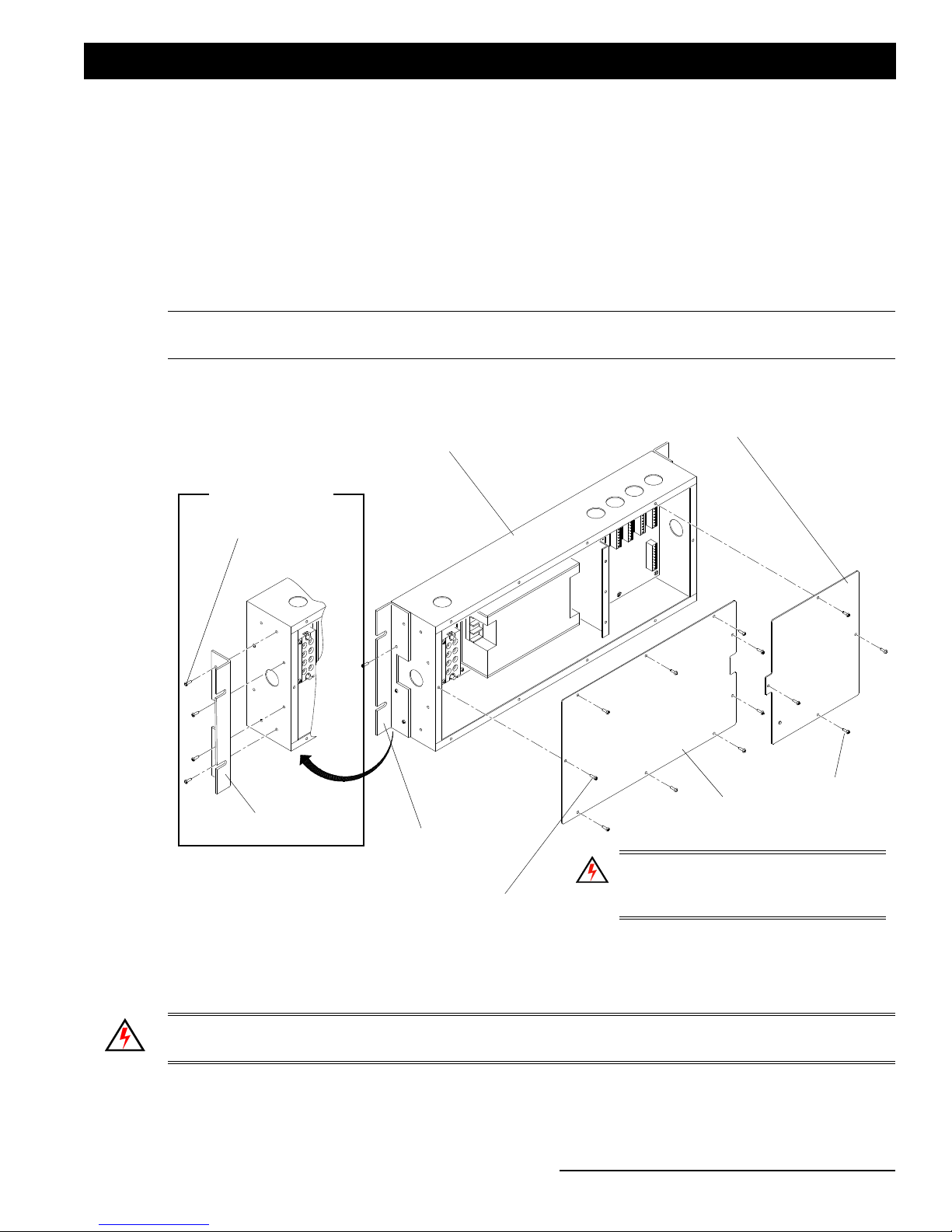
Step 3. If necessary, reconfigure mounting brackets (supplied) for wall or rack mounting as shown in Figure 5.
Figure 5: Configuring Mounting Brackets & Removing Covers
Step 4. Install unit.
Step 5. Remove covers from High Voltage and Low Voltage compartments.
WARNING! Ensure that power is removed from house service before connecting any wiring or cables to the
Emergency DMX Bypass Switch. This unit is not permitted to be used without the connection to earth (ground).
Step 6. Remove power from house service.
Bracket - Rack Mount
Configuration
Screw (x4)
Mounting Bracket
Power Supply (High
Voltage) Compartment Cover*
Emergency DMX Bypass
Switch Enclosure
Low Voltage
Compartment Cover
Screw (x9)
Screw (x4)
Mounting Bracket
WA R N I N G ! *Vent holes in the face of
the unit (in this cover) cannot face in
downward orientation.
Installation Guide Emergency DMX Bypass Switch
10 Installation
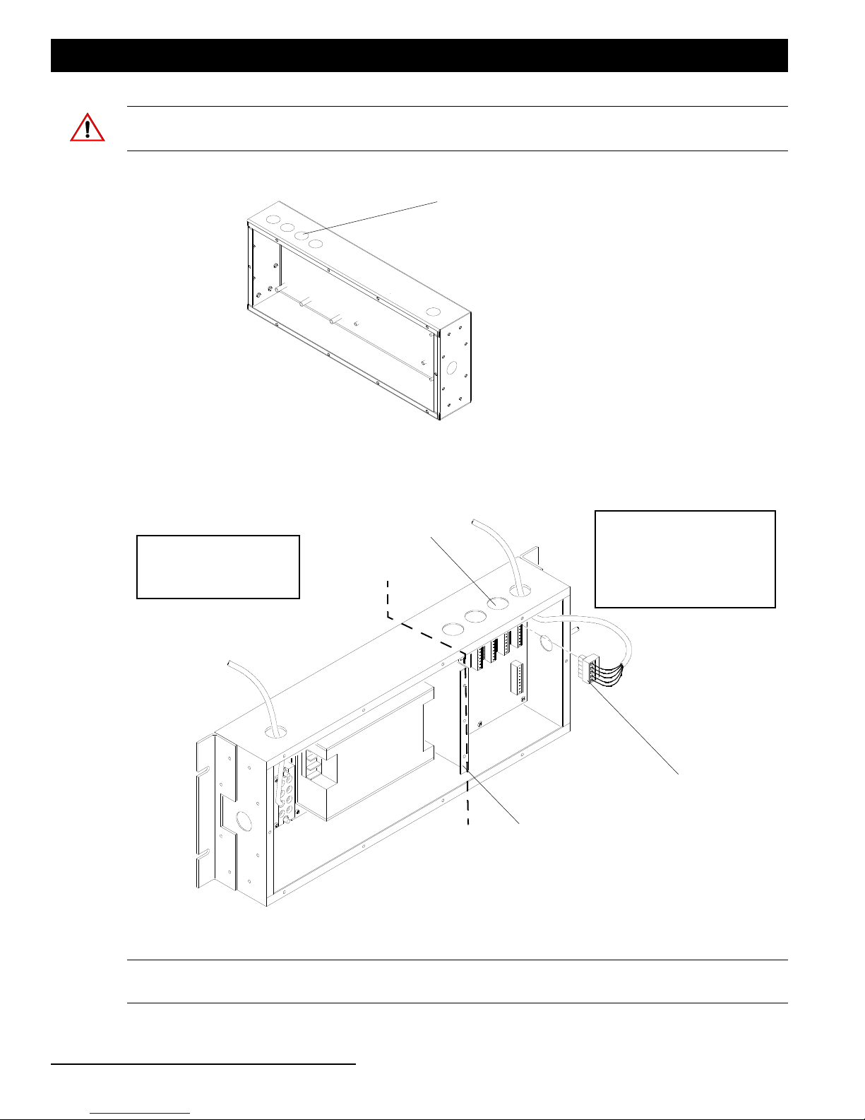
CAUTION: Knockouts are designed for 1/2-inch conduit and are to be punch towards inside of unit. When
punching knockouts, be careful not to damage printed circuit board, power supply, or internal wiring.
Step 7. As required, remove knockouts as shown in Figure 6.
Figure 6: Emergency DMX Bypass Switch Enclosure Knockouts
Step 8. Route power input wires and network cables as shown in Figure 7. See "Network Wiring" on page 11 for
connections.
Figure 7: Power Input and Network Wire Routing
Note: *DMX, Emergency, and Panic connections are accomplished with supplied connectors (shipped with unit).
See "Included Items" on page 7.
Knockouts for
1/2-inch conduit
Note: Only enclosure
shown for clarity.
Knockouts for
1/2-inch conduit
Route power wiring (100-240/277VAC) on
this side of unit. Must be N/E power.
NOTE: The unit is not permitted to be
used without the connection to earth
(ground).
Route DMX, Emergency, and
Panic wiring on this side of unit
DMX Connector Shown*
(supplied with unit)
High and Low Voltage
Separation Barrier
All Knockouts Accommodate
1/2-inch Conduit
Main Power Connections
(Conductor Requirements):
10-12 AWG (2.05 - 2.59mm²)
Conductor Requirements:
P o w e r C o n n e c t o r s P C B :
22 AWG (0.644mm²)
C o m m u n i c a t i o n C o n n e c t o r P C B :
30-14 AWG (.255 - 1.628mm²)
NOTE: Graphic shown is for illustrative purposes only. Conduit (not supplied,
by others) should be used and all local and national code followed.

Network Wiring 11
Emergency DMX Bypass Switch Installation Guide
Step 9. Connect power wiring as shown in Figure 8.
Figure 8: Input Power Connections
WARNING! Only use the supplied internal power supply. The unit is not permitted to be used without the
connection to earth (ground).
Step 10. Re-install compartment covers (Figure 5).
Step 11. After all network (low-voltage) connections are done, re-apply house power service.
5. Network Wiring
DMX Universe Connections
The Emergency DMX Bypass Switch provide connections for up to four DMX universes. Figure 9 illustrates the
internal connections and connection pin outs
Figure 9: DMX Universe Connections
NEUTRAL
LINE IN
GROUND
N/A
1GND
2ACLINE
3 AC NEUTRAL
100-240/277 VAC Power
Connection
NOTE: The unit is not permitted
to be used without the
connection to earth (ground).
Internal Power
Supply
Main Power Connections
(Conductor Requirements):
10-12AWG (2.05 - 2.59mm²)
DMX Universe Connections (up to four universes)
Conductor Requirements:
P o w e r C o n n e c t o r s P C B :
22 AWG (0.644mm²)
C o m m u n i c a t i o n C o n n e c t o r P C B :
30-14 AWG (.255 - 1.628mm²)
Installation Guide Emergency DMX Bypass Switch
12 Installation
WARNING! Only use the supplied internal power supply.
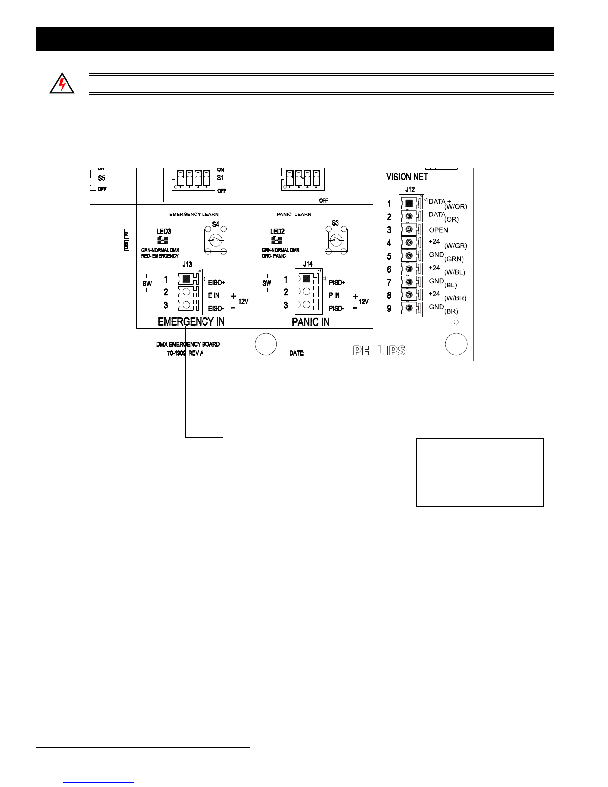
Emergency / Panic Connections
The Emergency DMX Bypass Switch is supplied with mating connectors for Emergency and Panic signal
connections. The printed circuit board has silk-screened pin out information. Figure 10 illustrates these connections.
Figure 10: Emergency and Panic Input Connections
Emergency Input Connection
Panic Input Connection
Vision.net Control
Connection
(FUTURE USE)
Conductor Requirements:
P o w e r C o n n e c t o r s P C B :
22 AWG (0.644mm²)
C o m m u n i c a t i o n C o n n e c t o r P C B :
30-14 AWG (.255 - 1.628mm²)
Setting Unit DIP Switches 13
Emergency DMX Bypass Switch Installation Guide
UNIT SETTINGS
1. Setting Unit DIP Switches
After making all connections, the unit is ready to set the operational DIP Switches.
Mode (DMX Splitter) DIP Switch
Set the mode DIP Switch as shown in Table 1 and Figure 11.
Table 1: DMX SPLITTER SELECTION
*After setting this operational mode, see "Emergency Selection DIP Switch" on page 14 for time settings.
Figure 11: Mode DIP Switch
SW1 SW2 SPLITTER OPERATION: EMERGENCY TIMING*
OFF N/A
SPLITTER DISABLED
(one to one patch)
DMX A (In) ->DMX A (Out)
DMX B (In) ->DMX B (Out)
DMX C (In) ->DMX C (Out)
DMX D (In) ->DMX D (Out)
SW3 OPERATION:
OFF FIXED
ON INTELLIGENT
ON OFF
DMX SPLITTER
(one in patched to two out)
DMX A (In) -> DMX A & B (Out)
DMX C (In) -> DMX C & D (Out)
PANIC TIMING*
SW4 OPERATION:
OFF FIXED
ON INTELLIGENTON ON
DMX SPLITTER
(one in patched to four out)
DMX A (In) -> DMX A,B,C,&D (Out)
DMX SPLITTER SELECTION
S5
Note: Default DIP Switch settings shown.

Installation Guide Emergency DMX Bypass Switch
14 Unit Settings
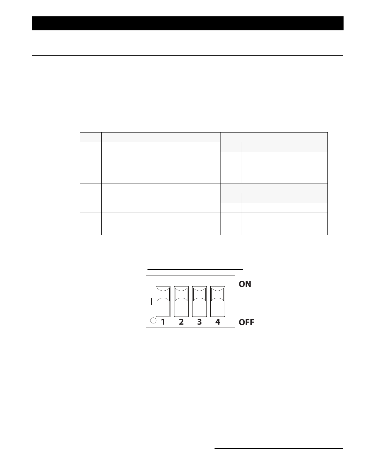
Emergency Selection DIP Switch
Set the emergency DIP Switch as shown in Figure 12. For setting release parameter.
Figure 12: Emergency DIP Switch
Panic Selection DIP Switch
Set the panic DIP Switch as shown in Figure 13. For setting output mode and input activation parameters.
Figure 13: Panic DIP Switch
Table 2: EMERGENCY DIP SWITCH SELECTION
SW1 SW2 RELEASE EMERGENCY AFTER
OFF OFF ONE (1) SECOND (default)
OFF ON TEN (10) SECONDS
ON OFF ONE (1) MINUTE FIXED OR INTELLIGENT*
ON ON TEN (10) MINUTES FIXED OR INTELLIGENT*
NOTE: *INTELLIGENT SHORTENS THE TIME SETTING WHEN A VALID DMX INPUT IS PRESENT.
SW3 EMERGENCY AND PANIC DMX OUTPUT MODE:
OFF OUTPUTS CHANNELS 1 - 512 @ FULL
ON OUTPUTS CAPTURED DMX (default)
SW4 INPUT ACTIVATION:
OFF NORMALLY OPEN (NO)
ON NORMALLY CLOSED (NC) (default)
EMERGENCY SELECTION
S1
Note: Default DIP Switch
settings shown.
Table 3: PANIC SELECTION
SW1 SW2 RELEASE PANIC AFTER
OFF OFF ONE (1) SECOND (default)
OFF ON TEN (10) SECONDS
ON OFF ONE (1) MINUTE FIXED OR INTELLIGENT*
ON ON TEN (10) MINUTES FIXED OR INTELLIGENT*
NOTE: *INTELLIGENT SHORTENS THE TIME SETTING WHEN A VALID DMX INPUT IS PRESENT.
SW3 EMERGENCY AND PANIC DMX OUTPUT MODE:
OFF OUTPUTS CHANNELS 1 - 512 @ FULL
ON OUTPUTS CAPTURED DMX (default)
SW4 INPUT ACTIVATION:
OFF NORMALLY OPEN (NO) (default)
ON NORMALLY CLOSED (NC)
PANIC SELECTION
S2
Note: Default DIP Switch
settings shown.

Status LEDs and Buttons 15
Emergency DMX Bypass Switch Installation Guide
2. Status LEDs and Buttons
The following describes the status LEDs and test buttons on located on the low-voltage compartment cover as
indicated in Figure 14.
Figure 14: Status LEDs and Test Buttons
DMX Status LEDs (one for each DMX port)
• OFF - No DMX Activity (receiving or transmitting)
• GREEN - Receiving DMX IN (Normal State)
• RED (Solid or Blinking) - Emergency DMX pattern is being Transmitted
• ORANGE (Solid or Blinking) - Panic DMX pattern is being Transmitted
Note: In Splitter mode, the LEDs corresponding to the ports set up to receive DMX will turn GREEN to indicate
Receiving DMX IN. The ports that are coupled to the Receiving port will also turn GREEN but with a small mix of
RED (not fully ORANGE).
Unit Status LED
• OFF - Unit is not powered
• Slow GREEN blink for Normal operating mode
• Port LEDs will Turn Green if receiving DMX
• Port LEDs will Turn GREEN (with a small mix of RED) when controlled by another Splitter Port
• RED blinks indicate Emergency condition (Input or Test)
• Port LEDs will turn Red to indicate Emergency (triggered by an Input)
• Port LEDs will toggle between Red and Green to indicate Emergency (triggered by a Test Emergency
button)
Emergency Test
Button
DMX Universe Status LEDs
Emergency DMX Bypass Switch Status LED
Panic Test
Button

Installation Guide Emergency DMX Bypass Switch
16 Notice To Contractor
• ORANGE blinks indicate Panic condition (Input or Test)
• Port LEDs will turn Orange to indicate Panic (triggered by an Input)
• Port LEDs will toggle between Orange and Green to indicate Panic (triggered by a Test Panic button)
Test Buttons
The units contains two test buttons. One button is for triggering (testing) Emergency Mode. The other button is for
triggering (testing) Panic mode.
• Hold for 3 seconds to trigger a mode test
•The mode test stays enabled for ten minutes and then automatically turns off OR,
• Press button at anytime to exit mode test.
NOTICE TO CONTRACTOR
Technical Services Checkout Procedure
DO NOT APPLY POWER TO THE LIGHTING CONTROL SYSTEM!
No part of this system may be energized or operated until the installation has been approved by a Strand Lighting
Technical Services Representative. Violation of this Requirement may damage components and therefore constitute
misuse under standard warranty terms. Such misuse may relieve Strand Lighting of any and all further obligations
under the terms of this warranty.
Equipment MUST be installed per the Strand Lighting drawings.
All installation and wire terminations MUST be completed per the Strand Lighting drawings prior to the arrival of the
Technical Services Representative:
1) Input power must be connected to the system, but not energized. The unit is not permitted to be used without
the connection to earth (ground).
2) All loads must be connected.
3) All control and signal wiring must be installed and terminated - including DMX512, Emergency, Panic, etc.
4) All equipment, including controllers, accessories, keys, cables and manuals must be in place.
5) Personnel for training (i.e. the users), as well as any other personnel required by contract and/or
specification must be available for training at the completion of the Checkout and Energization.
6) An owner (or authorized representative), as well as any other personnel required by contract and/or
specification will be present to accept the system.
The Technical Services Representative will only be able to:
• Ensure that the system is properly installed and functions correctly, including troubleshooting and providing guid-
ance to the contractor to correct any problems.
• Train personnel in the operation of the Lighting Control System.
The Technical Services Representative will not be able to:
• Install equipment or make electrical connections required of the installing contractor, including DMX512, Emer-
gency, Panic, and/or any other connections that require a licensed electrician.
• Return to instruct any personnel who missed the original training session.
If the above requirements have not been met, the Technical Services Representative will be required to leave the job
site. Return trips to complete the Technical Services Checkout require a separate Purchase Order and will be invoiced
at the cost of travel (including per diem and travel time door-to-door), hourly labor, and a minimum daily on-site
charge. Rescheduling will require 3 weeks notice, subject to Technical Services Representative availability.

Electrical 17
Emergency DMX Bypass Switch Installation Guide
-------------------------------------------------------------------------------------------------------------------------------------------
Please feel free to contact Strand Lighting Technical Services (1-214-647-7880) should there be any questions
regarding the installation of the equipment or requirements regarding the Technical Services Checkout.
When all requirements have been met and the system is ready for inspection, please download and complete the Field
Service/Commissioning Request Form (PDF). This form can be found on the Main Support Page of the Strand
Lighting website: www.strandlighting.com
PRODUCT SPECIFICATIONS
1. Electrical
Input Power: 100-240/277VAC, 50-60Hz, 0.6 A, 1 Phase
Output Power: 24VDC, 42W / 1.75A
DMX Universes (Input): 4
Panic (Input): 1
Emergency (Input): 1
2. Environmental
Storage: -25° to 85° C
Operating: 0° to 40° C
Relative Humidity: 5 to 95% (non-condensing)
Compliance: cETLus: UL 924, CSA C22.2#141,
CE: IEC 60730-1, 61347-1 & 61347-2-3
EMC: FCC 47CFR PT 15 SPT B, EN55022, EN55024, EN61000-3-2, EN61000-3-3
3. Mechanical
Color: Black
Construction: Steel Enclosure
Weight: 9.7 lbs.
1GND
2ACLINE
3ACNEUTRAL
OUTPUT + 4
OUTPUT + 5
OUTPUT - 6
OUTPUT - 7
19.00 Inches
17.00 Inches
7.00 Inches
Depth: 3-3/16 Inches
High-Voltage Section Low-Voltage Section

Part No:85-6418
Table of contents


