manuals.online logo
Brands
  1. Home
  2. •
  3. Brands
  4. •
  5. ORiNG
  6. •
  7. Switch
  8. •
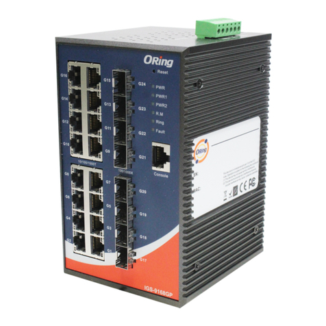
  9. ORiNG IGS-9084GP User manual

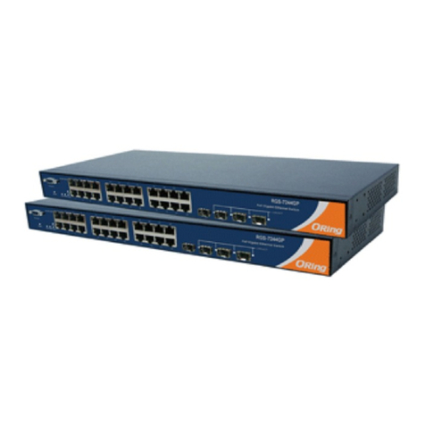
ORiNG IGS-9084GP User manual

IGS-9084GP
PWR
PWR1
PWR2
10/100/1000T
G8
G6
G4
G2
G12
G11
G10
G9
100/1000X
G7
G5
G3
G1
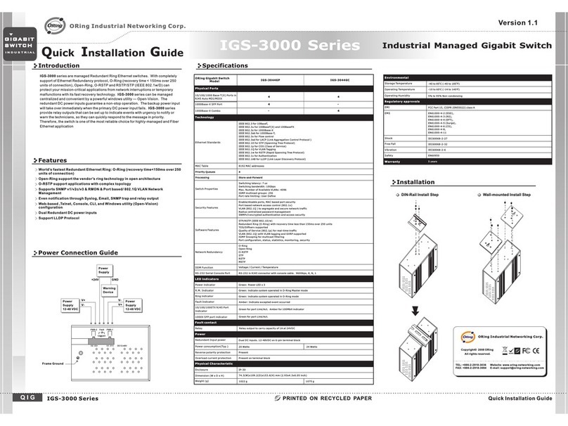
Quick Installation Guide
Version 1.0
Quick Installation Guide
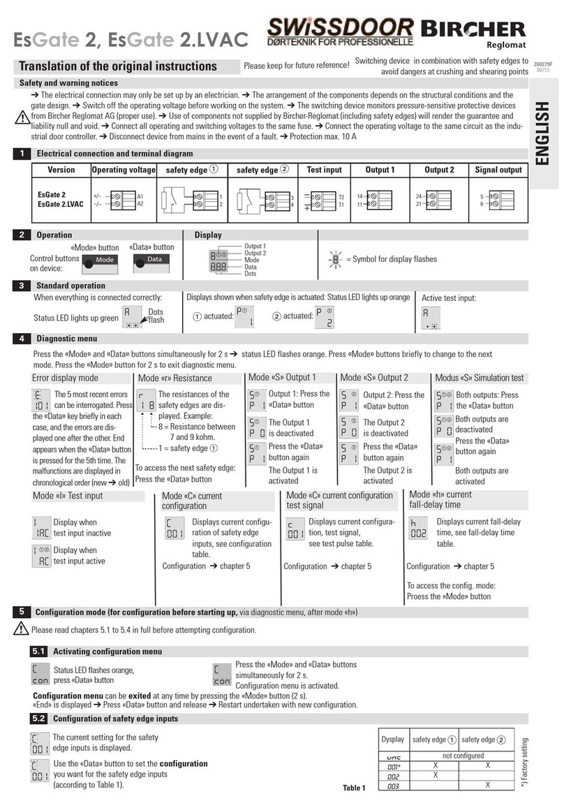
Introduction
PRINTED ON RECYCLED PAPER
The IGS-9084GP series is a managed Ethernet switch with
8x10/100/1000Base-T(X) ports and 4x100/1000Base-X SFP ports. With
complete support of Ethernet redundancy protocols, O-Ring (recovery time
< 30ms for over 250 connected devices) and MSTP (RSTP/STP compatible)
can protect your mission-critical applications from network interruptions or
temporary malfunctions. With a wide operating temperature from -40~70 C,
the device can be managed centrally via ORing’s proprietary Open-Vision
platform as well as via Web-based interfaces, Telnet and console (CLI).
o
Preparation
Before you begin installing the switch, make sure you have all of the package
contents available and a PC with Microsoft Internet Explorer 6.0 or later, for
using web-based system management tools.
Elevated Operating Ambient:
Reduced Air Flow:
Mechanical Loading:
If installed in a closed or multi-unit rack
assembly, the operating ambient temperature of the rack environment may be
greater than room ambient. Therefore, consideration should be given to
installing the equipment in an environment compatible with the maximum
ambient temperature (Tma) specified by the manufacturer.
Installation of the equipment in a rack should be such
that the amount of air flow required for safe operation of the equipment is
not compromised.
Mounting of the equipment in the rack should be
such that a hazardous condition is not achieved due to uneven mechanical
loading.
Safety & Warnings
Dimension
Panel Layouts
11
1. Power LED
2. PWR1 LED
3. PWR2 LED
4. R.M. status LED
5. Ring status LED
6. Faulty relay indicator
7. Console port
8. Link/action LED for Gigabit Ethernet ports
9. Duplex LED for Gigabit Ethernet ports
10. Gigabit Ethernet ports
11. SFP port
12. Link/action LED for SFP port
Package Contents
Contents
DIN-rail Kit
CD
IGS-9084GP
Pictures Number
X1
X1
X1
Front View
Top Panel
The device is shipped with the following items. If any of these items is
missing or damaged, please contact your customer service representative for
assistance.
GIGABIT
INDUSTRIAL
SWITCH
Industrial Managed Gigabit Switch
QIG
Console Cable
X2
X1
X1
Wall-mount Kit
33.0
30.0
12.5
105.5
10.9
15.0
70.5
154.0
96.4
87.0
48.0
17.5
94.0
124.0
48.0
58.0
7.50
R2.5
R3.95
66.25
48.75
95.9
IGS-9084GP
PWR
PWR1
PWR2
10/100/1000T
G8
G6
G4
G2
G12
G11
G10
G9
100/1000X
G7
G5
G3
G1
10
7
1
2
3
4
5
6
Rear View
12
PWR-1PWR-2
1A@24V
DC 48V
V2- V2+ V1- V1+
Fault
1
1. Wall-mount screw holes
2. Din-rail screw holes
2
1. Terminal blocks: PWR1, PWR2
(12-48V DC), Relay
2. Ground wire.
1
Installation
Step 1:
Step 2:
Slant the switch and screw the Din-rail kit onto the back of the switch, right in
the middle of the back panel.
Slide the switch onto a DIN-rail from the Din-rail kit and make sure the switch
clicks into the rail firmly.
DIN-rail Installation
Step 1:
Step 2:
Step 3:
Screw the two pieces of wall-mount kits onto both ends of the rear panel of the
switch. A total of six screws are required, as shown below.
Use the switch, with wall mount plates attached, as a guide to mark the
correct locations of the four screws.
Insert a screw head through the large parts of the keyhole-shaped apertures,
and then slide the switch downwards. Tighten the screws for added stability.
Wall-mounting
IGS-9084GP
QIG IGS-9084GP 1907-2-29-IGS9084GP-1.0
Circuit Overloading: Consideration should be given to the connection of the
equipment to the supply circuit and the effect that overloading of the circuits might have
on overcurrent protection and supply wiring. Appropriate consideration of equipment
nameplate ratings should be used when addressing this concern.
12
8
9
IGS-9084GP
PWR
PWR1
PWR2
10/100/1000T
G8
G6
G4
G2
G12
G11
G10
G9
100/1000X
G7
G5
G3
G1
Network Connection
The switch provides standard Ethernet ports. According to the link type, the switch uses
CAT 3,4,5,5e UTP cables to connect to any other network devices (PCs, servers,
switches, routers, or hubs). Please refer to the following table for cable
specifications.
Cable Types and Specifications:
Cable Type Max. Length Connector
10BASE-T Cat. 3, 4, 5 100-ohm UTP 100 m (328 ft) RJ-45
100BASE-TX Cat. 5 100-ohm UTP UTP 100 m (328 ft) RJ-45
1000BASE-T Cat. 5 / Cat. 5e 100-ohm UTP UTP 100 m (328 ft) RJ-45
QIG Quick Installation Guide
PRINTED ON RECYCLED PAPER
Version 1.0
Quick Installation Guide
Resetting
To reboot the switch, press the button for 2-3 seconds.
To restore the switch configurations back to the factory defaults, press the button for 5 seconds.
Reset
Reset
Specifications
GIGABIT
INDUSTRIAL
SWITCH
Industrial Managed Gigabit Switch
For pin assignments for different types of cables, please refer to the following
tables.
10/100 Base-T(X) MDI/MDI-X
Pin Number MDI port MDI-X port
1TD+(transmit)RD+(receive)
2TD-(transmit)RD-(receive)
3 RD+(receive) TD+(transmit)
4NotusedNotused
5NotusedNotused
6 RD-(receive) TD-(transmit)
7NotusedNotused
8NotusedNotused
Note: “+” and “-” signs represent the polarity of the wires that make up each
wire pair.
To connect the console port to an external management device, you need an RJ-45 to
DB-9 cable, which is also supplied in the package. Below is the console port pin
assignment information.
Console Port Pin Definition
PC (male) pin assignment RS-232 with DB9 (female) pin
assignment (RJ45-DB9 cable) RJ45 pin assignment
PIN#2 RxD PIN#2 RxD PIN#2 RxD
PIN#3TxD PIN#3TxD PIN#3TxD
PIN#5 GND PIN#5 GND PIN#5 GND
Wiring
The switch supports dual redundant power supplies, Power Supply1
(PWR1) and Power Supply 2 (PWR2). The connections for PWR1,
PWR2 and the RELAY are located on the terminal block.
Insert the negative/positive wires into the V-/V+ terminals,
respectively.
To keep the DC wires from pulling loose, use a small flat-
blade screwdriver to tighten the wire-clamp screws on the front of the
terminal block connector.
STEP 1:
STEP 2:
PWR-1PWR-2
1A@24V
V2-V2+ V1-V1+
Fault
Power inputs
The two sets of relay contacts of the 6-pin terminal block connector are used to detect user-
configured events. The two wires attached to the fault contacts form an open circuit when a
user-configured when an event is triggered. If a user-configured event does not occur, the
fault circuit remains closed.
Relay contact
Grounding and wire routing help limit the effects of noise due to electromagnetic
interference (EMI). Run the ground connection from the ground screws to the grounding
surface prior to connecting devices.
Grounding
Configurations
After installing the switch, the green power LED should turn on. Please refer to the
following tablet for LED indication.
1. Launch the Internet Explorer and type in IP address of the switch. The default static IP address is
192.168.10.1
2. Log in with default user name and password
(both are ). After logging in, you should
see the following screen. For more information
on configurations, please refer to the user
manual. For information on operating the switch
using ORing’s Open-Vision management utility,
please go to ORing website.
admin
Follow the steps to set up the switch:
ORingSwitchModel IGS-9084GP
Physical Ports
Technology
Ethernet Standards
IEEE 802.3 for 10Base-T
IEEE 802.3u for 100Base-TX and 100Base-FX
IEEE 802.3z for 1000Base-X
IEEE 802.3ab for 1000Base-T
IEEE 802.3ad for LACP (Link Aggregation Control Protocol)
IEEE 802.3x for Flow control, IEEE 802.1D for STP (Spanning Tree Protocol)
IEEE 802.1p for COS (Class of service)
IEEE 802.1Q for VLAN Tagging
IEEE 802.1w for RSTP (Rapid Spanning Tree Protocol
IEEE 802.1s for MSTP (Multiple Spanning Tree Protocol)
IEEE 802.1x for Authentication
Power
Redundant Input power
Power consumption(Typ.)
Dual DC inputs. 12-48VDC on 6-pin terminal block
11 watts max.
Overload current protection Present
Physical Characteristic
Enclosure IP-30
Dimension(WxDxH) 96.4(W)x105.5(D)x154(H)mm(3.8x4.15x6.06inch)
10/100/1000Base-T(X) Ports
in RJ45 Auto MDI/MDIX
MAC Table 8K
RS-232 Serial Console Port
Priority Queues 8
Processing Store-and-Forward
Switch Properties
Switch latency: 7 us
Switch bandwidth: 24Gbps
Max. Number of Available VLANs: 256
IGMP multicast groups: 128 for each VLAN
Port rate limiting: User Define
Security Features
Device Binding security feature
Enable/disable ports, MAC based port security
Port based network access control (802.1x)
VLAN (802.1q) to segregate and secure network traffic
Radius centralized password management
SNMPv3 encrypted authentication and access security
Https / SSH enhance network security
Software Features
STP/RSTP/MSTP (IEEE 802.1D/w/s)
Redundant Ring (O-Ring) with recovery time less than 10ms over 250 units
TOS/Diffserv supported
Quality of Service (802.1p) for real-time traffic
VLAN (802.1Q) with VLAN tagging and GVRP supported
IGMP Snooping for multicast filtering
IP-based bandwidth management
Application-based QoS management
DOS/DDOS auto prevention
Port configuration, status, statistics, monitoring, security
DHCP Server / Client support
SMTP Client
Modbus TCP
Network Redundancy O-Ring, Open-Ring, O-chain, STP, RSTP, MSTP
RS-232 in RJ45 connector with console cable. Baud rate setting: 115200bps, 8, N, 1
Weight (g) 1190 g
Warning / Monitoring System
Syslog server / client to record and view events
Include SMTP for event warning notification via email
Event selection support
8
100/1000Base-X with SFP port 4
Jumbo frame Up to 9.6K Bytes
Weight (g) 710 g 740 g722 g 735 g 735 g 740 g
Environmental
-40to85 C(-40to185F)
oo
Storage Temperature
-40to70 C(-40to158F)
oo
Operating Temperature
5% to 95% Non-condensingOperating Humidity
Regulatory Approvals
FCC Part 15, CISPR (EN55022) class AEMI
EN61000-4-2 (ESD), EN61000-4-3 (RS), EN61000-4-4 (EFT), EN61000-4-5 (Surge),EN61000-4-6 (CS), EN61000-4-8, EN61000-4-11
EMS
IEC60068-2-27Shock
IEC60068-2-32
IEC60068-2-6Vibration
EN60950-1
Safety
Free Fall
Warranty
5 years
1000Base-T MDI/MDI-X
Pin Number MDI port MDI-X port
1 BI_DA+ BI_DB+
2 BI_DA- BI_DB-
3 BI_DB+ BI_DA+
4BI_DC+BI_DD+
5 BI_DC- BI_DD-
6 BI_DB- BI_DA-
7 BI_DD+ BI_DC+
8 BI_DD- B I_DC-
LED Color Status Description
PWR Gree n On DC power on
PWR 1 Green On DC power module 1 activated
PWR 2 Green On DC power module 2 activated
R.M Green On Ring Master
On Ring enabled
Ring Green Blinking Ring structure is broken (i.e. part of the ring is
disconnected)
Fault Amber On Faulty relay (power failure or port disconnected)
10/100/1000Base-T(X) Gigabit Ethernet ports
Green On Port link at 1000Mbps
Amber On Port l ink at 10/100Mbps
LNK/ACT
with speed
Green/Amber Blinking Data transmitted
SFP
On Port link up
LNK/ACT Green
Blinking Data transmitted
IGS-9084GP
IGS-9084GP
1000Base-T RJ-45 Port
Pin Number Assignment
1BI_DA+
2BI_DA-
3BI_DB+
4BI_DC+
5BI_DC-
6BI_DB-
7BI_DD+
8BI_DD-
ORing Industrial Networking Corp.
Copyright© 2014 ORing
All rights reserved.
TEL: +886-2-2218-1066
FAX: +886-2-2218-1014
Website: www.oring-networking.com
E-mail: [email protected]

Other ORiNG Switch manuals

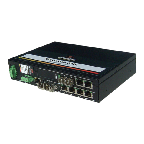
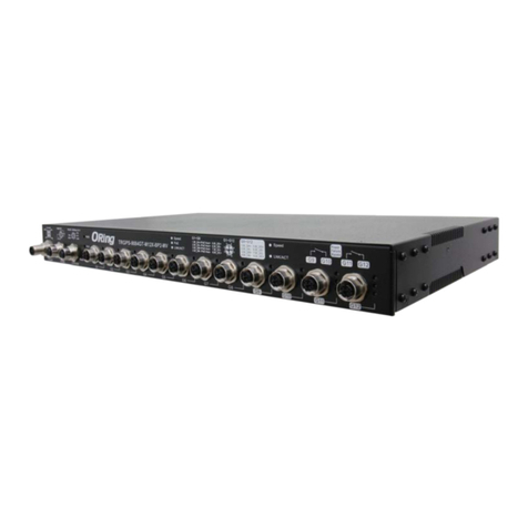
ORiNG TRGPS-9084TG-M12X-BP2-MV User manual

ORiNG

ORiNG TRGPS-9084TG-M12X-BP2-MV User manual

ORiNG IES-3080 Series User manual

ORiNG

ORiNG IES-3080 Series User manual

ORiNG TGPS-9084GT-M12X-BP2-MV User manual

ORiNG

ORiNG TGPS-9084GT-M12X-BP2-MV User manual

ORiNG IGS-1042GPA User manual

ORiNG

ORiNG IGS-1042GPA User manual

ORiNG IGPS-9084GP-LA User manual

ORiNG

ORiNG IGPS-9084GP-LA User manual

ORiNG IDS-342GT User manual

ORiNG

ORiNG IDS-342GT User manual

ORiNG TES-250-M12 User manual

ORiNG

ORiNG TES-250-M12 User manual

ORiNG IGS-P9164 Series User manual

ORiNG

ORiNG IGS-P9164 Series User manual

ORiNG IGPS-1082GP Series User manual

ORiNG

ORiNG IGPS-1082GP Series User manual

ORiNG TGPS-9084GT-M12X-BP2-24V User manual

ORiNG

ORiNG TGPS-9084GT-M12X-BP2-24V User manual

ORiNG TPS-1080-M12 User manual

ORiNG

ORiNG TPS-1080-M12 User manual

ORiNG TGPS-9080-M12A-MV User manual

ORiNG

ORiNG TGPS-9080-M12A-MV User manual

ORiNG IGS-9084GP-LA User manual

ORiNG

ORiNG IGS-9084GP-LA User manual

ORiNG DGS-7084GCP-AIO_S SERIES User manual

ORiNG

ORiNG DGS-7084GCP-AIO_S SERIES User manual

ORiNG TRGPS-9084GT-M12X-BP2-MV User manual

ORiNG

ORiNG TRGPS-9084GT-M12X-BP2-MV User manual

ORiNG IGS-1050A User manual

ORiNG

ORiNG IGS-1050A User manual

ORiNG IGS-9844 User manual

ORiNG

ORiNG IGS-9844 User manual

ORiNG TGPS-9084GT-M12 User manual

ORiNG

ORiNG TGPS-9084GT-M12 User manual

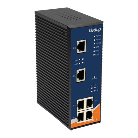
ORiNG IPS-2042 Series User manual

ORiNG

ORiNG IPS-2042 Series User manual

ORiNG IES-3240 User manual

ORiNG

ORiNG IES-3240 User manual

ORiNG TGPS-9168GT-M12-BP2-24V User manual

ORiNG

ORiNG TGPS-9168GT-M12-BP2-24V User manual

ORiNG IGPS-9080-24V User manual

ORiNG

ORiNG IGPS-9080-24V User manual

ORiNG IGPS-9084GP User manual

ORiNG

ORiNG IGPS-9084GP User manual

ORiNG IPS-3082GC-AT User manual

ORiNG

ORiNG IPS-3082GC-AT User manual

Popular Switch manuals by other brands

Cisco Catalyst 2955 Series Hardware installation guide

Cisco

Cisco Catalyst 2955 Series Hardware installation guide

Cyclades User's Guide user guide

Cyclades

Cyclades User's Guide user guide

Eneo IAR-7SH1024MMA user manual

Eneo

Eneo IAR-7SH1024MMA user manual

Fermax 8944 manual

Fermax

Fermax 8944 manual

MTS Systems ATS-21AG Operator's manual

MTS Systems

MTS Systems ATS-21AG Operator's manual

WOODLAND SCENICS JP5702 manual

WOODLAND SCENICS

WOODLAND SCENICS JP5702 manual

Ruijie Networks RG-S8605E Hardware  installation and reference guide

Ruijie Networks

Ruijie Networks RG-S8605E Hardware installation and reference guide

Edimax HP-5101ES datasheet

Edimax

Edimax HP-5101ES datasheet

Balluff BES M30MF2-PSC15F-BV02-EXD user guide

Balluff

Balluff BES M30MF2-PSC15F-BV02-EXD user guide

Altusen KH-88 Quick start quide

Altusen

Altusen KH-88 Quick start quide

ADC Cuda 12000 installation guide

ADC

ADC Cuda 12000 installation guide

SEIAOTEK ST-G16T user manual

SEIAOTEK

SEIAOTEK ST-G16T user manual

Perle RPS1620 user guide

Perle

Perle RPS1620 user guide

l-com IES Series user guide
l-com
l-com IES Series user guide

Equinox Systems ESP-2 MI installation guide

Equinox Systems

Equinox Systems ESP-2 MI installation guide

LITETRONICS BSC02 user guide

LITETRONICS

LITETRONICS BSC02 user guide

Dell S6000-ON installation guide

Dell

Dell S6000-ON installation guide

Edge-Core AS7712-32X Safety and regulatory information

Edge-Core

Edge-Core AS7712-32X Safety and regulatory information

manuals.online logo
manuals.online logoBrands
  • About & Mission
  • Contact us
  • Privacy Policy
  • Terms and Conditions

Copyright 2025 Manuals.Online. All Rights Reserved.