Streetwize SWBC18 User manual

SWBC18 AW 2018 back.indd 1 12/06/2018 08:25
It is always advisable to wear safety glasses/gloves when using Booster Cables
READ THE FOLLOWING
INSTRUCTIONS VERY CAREFULLY
1Cables can be damaged by incorrect use, see general notes.
2 Ensure both batteries are of the same voltage (i.e. 12v-12v or 24v-24v do
not mix).
3Please be advised that the continuous charge rate for these cables
is 240 Amp.
4Always ensure that when connected to at least one battery, the battery
crocodile clips do not touch the car body work. Position each vehicle so that they
do not touch, turn off all switches and ignition, place the gear lever in neutral and
put the handbrake on.
5Connect the red (positive +) lead to the (positive +) terminals of both vehicles
batteries.
Connect the black (negative -) lead FIRST to the (negative -) terminal of the
“Starter vehicles Battery”. Then connect the other end to any suitable metal
earthing point on the faulty vehicle. DO NOT connect the other end of the black
(negative -) lead to the flat battery of the faulty vehicle. The old standard
method of “red 2 red” and “black 2 black” is no longer suitable due to
possible damage to any onboard ECU’s (electronic control units - such as
computers, engine management systems, air bags, audio units, etc).
6Start the vehicle, and after some minutes remove the Booster Cables from the
former flat battery, starting with the Negative clip from both batteries, followed by
the Positive clips from both batteries. Once this operation is complete ensure the
cables are free from the engine area & all moving parts.
7If after several attempts to charge the battery with no success, then it is
evident that a discharged battery is not at fault.
8Fold up the Booster Cables and place back into their bag.
9Never Smoke when working near a Battery! Do not create sparks
of any kind at all.
10 Battery Acid is dangerous, if any Acid touches the eyes consult
a Doctor immediately.
11 Important Notice;
No responsibility is taken for incorrect use of this equipment.
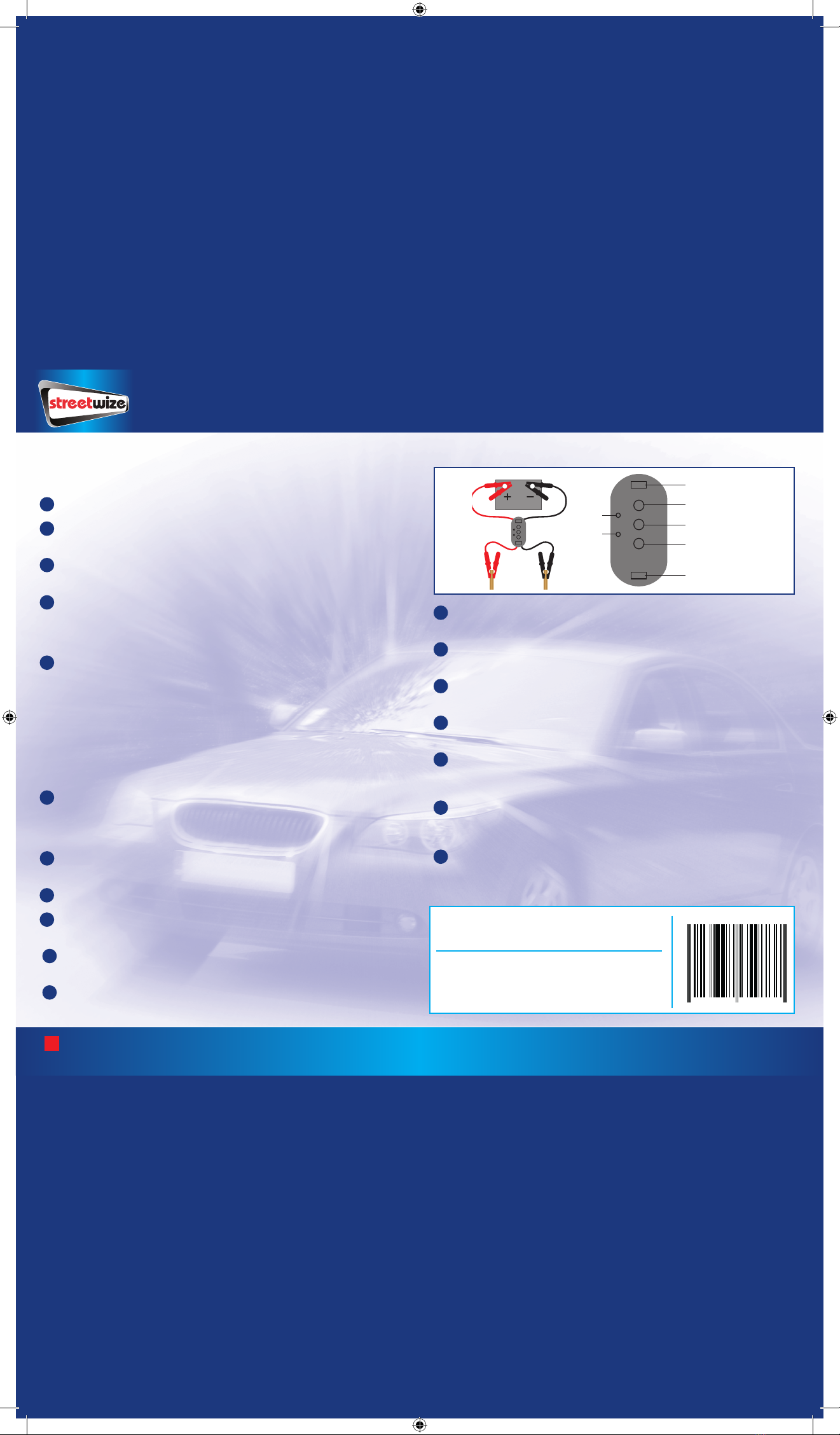
TEST BATTERY/ALTERNATOR OF A VEHICLE
1Isolate one of the two red crocodile clips/positive (+) and connect to a
non-conductive object such as a piece of wood.
2Isolate one of the two black crocodile clips/negative (-) and connect to a
non-conductive object such as a piece of wood.
3Connect the remaining red crocodile clip positive (+) to the positive (+)
terminal on the battery of the vehicle.
4Connect the remaining black crocodile clip negative (-) to the negative
terminal on the battery of the vehicle.
512V or 24V LED will illuminate to confirm battery type. Check the colour of
the LED to indicate battery charge level and change accordingly at the earliest
opportunity.
6Start/turn on the vehicle to determine the condition of the alternator. If the
alternator warning LED does not light, this will indicate a defective alternator,
in this instance please refer to a qualified vehicle mechanic.
7When finished, turn off your vehicle engine, remove the battery clamps from
the battery and non-conductive materials, place back in the storage case, and
store in a clean, dry place out of reach of children.
Streetwize Accessories:
Unit 1, Royce Trading Estate, Ashburton Road West,
Trafford Park, Manchester M17 1RY
Technical enquiries:
www.streetwizeaccessories.com
5 026637 659737
SWBC18
GREEN LED - Fully charged battery
ALTERNATOR OK
HIGH
LOW
OK
CONNECTION
REVERSED
24V
12V
BATTERY TESTER
12V
24V
RED LED - Alternator OK
RED LED - Flat battery
RED LED - Cables not
connected correctly
YELLOW LED - Charged battery
Non-conductive
objects
(i.e. piece
of wood)
Battery
3 4
1 2
SWBC18 AW 2018 back.indd 2 12/06/2018 08:25
Other Streetwize Cables And Connectors manuals


