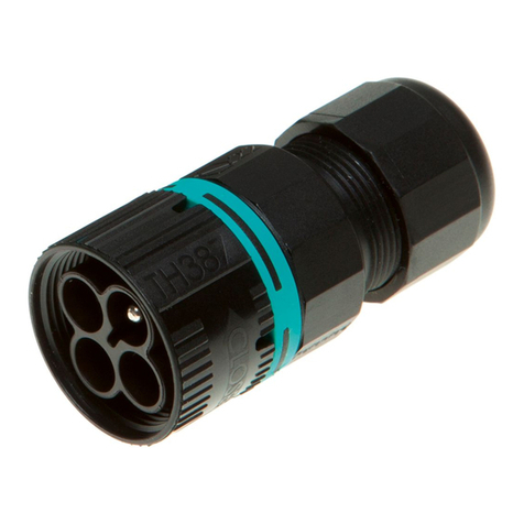
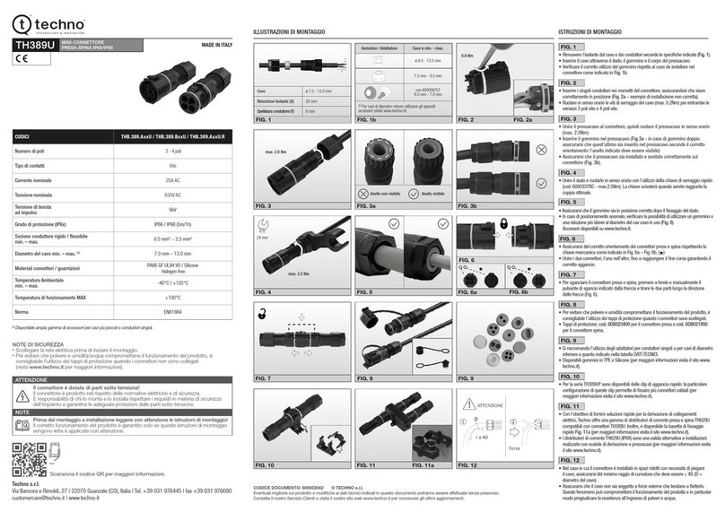
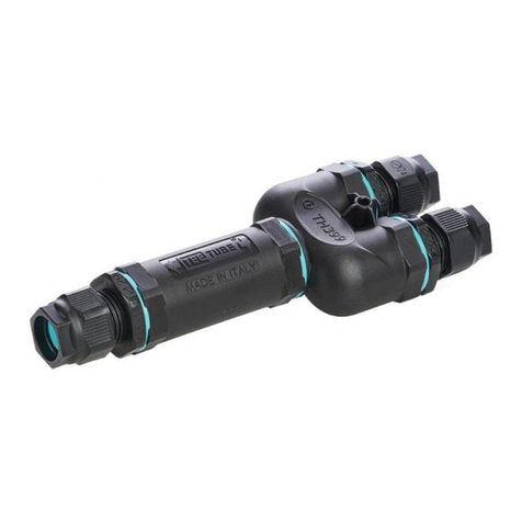
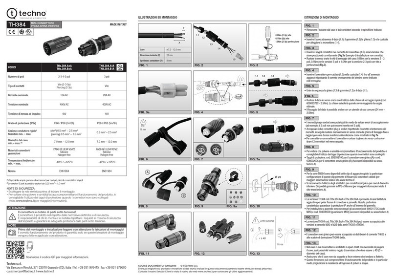
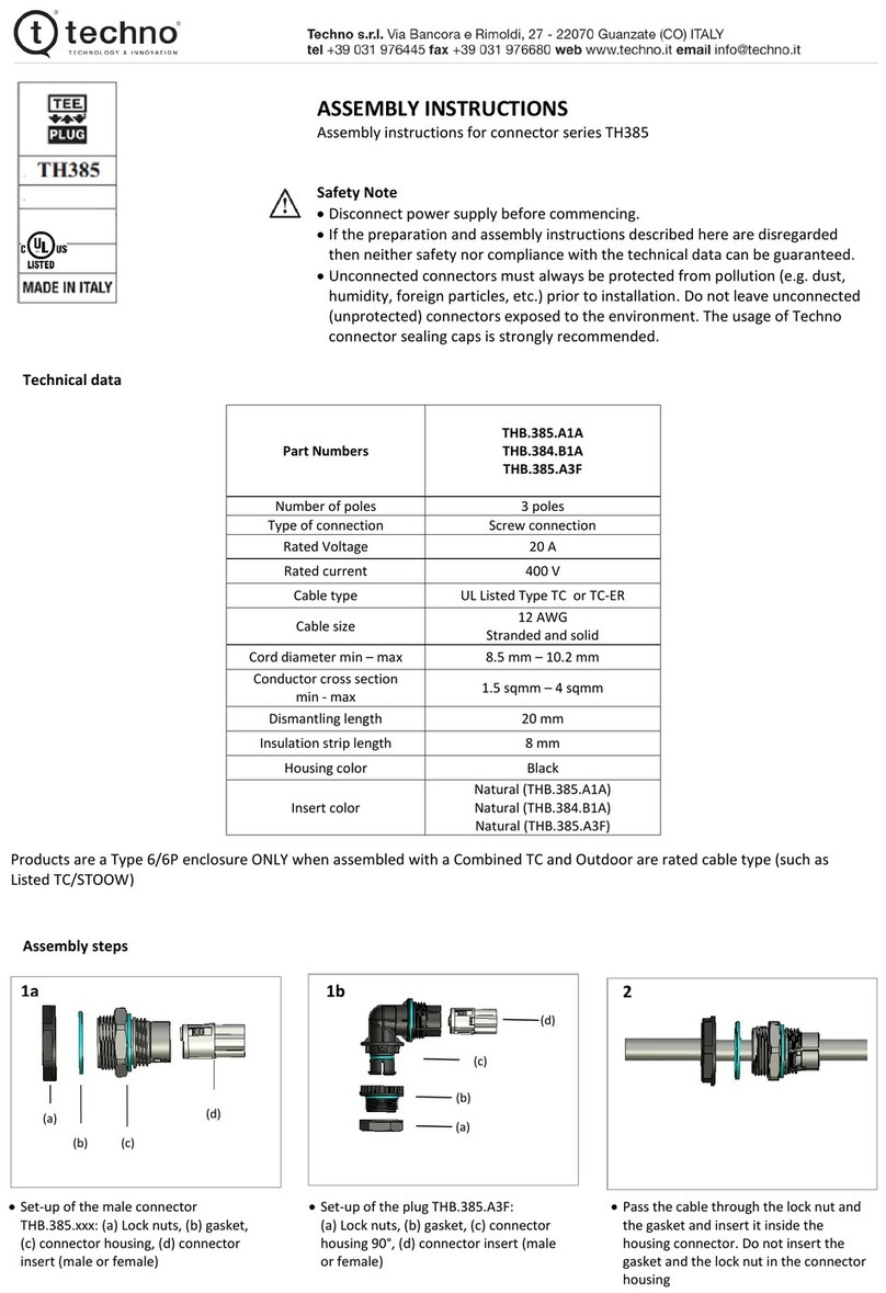
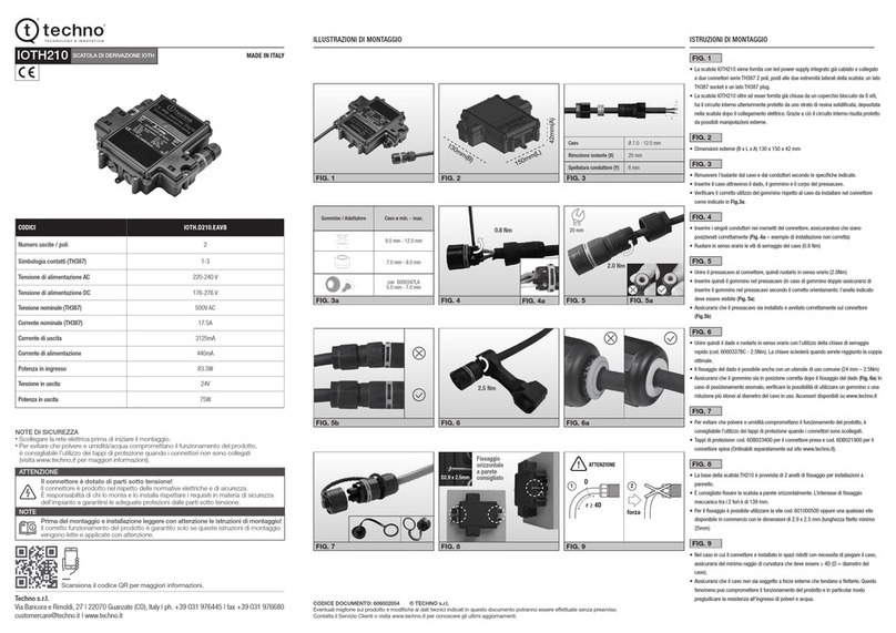
Techno THB.381.A2 Series User manual

NOTE DI SICUREZZA
•Scollegare la rete elettrica prima di iniziare il montaggio.
•Per evitare che polvere e umidità/acqua compromettano il funzionamento del prodotto,
è consigliabile l’utilizzo dei tappi di protezione quando i connettori non sono collegati
(visita www.techno.it per maggiori informazioni).
MICRO-CONNETTORE
PRESA-SPINA IP66/IP68/IP69K
ILLUSTRAZIONI DI MONTAGGIO ISTRUZIONI DI MONTAGGIO
DATI TECNICI (visita www.techno.it)
Techno s.r.l.
Via Bancora e Rimoldi, 27 | 22070 Guanzate (CO), Italy | ph. +39 031 976445 | fax +39 031 976680
TH381
CODICI THB.381.A2x/THB.381.A2x.x
THB.381.B2x/THB.381.B2x.x
THB.381.A3x/THB.381.A3x.x
THB.381.B3x
Numero di poli 2 poli 3 poli
Tipo di contatti Vite Vite
Corrente nominale 10A AC/DC 10A AC/DC
Tensione nominale 500V(3) AC (12V-60V DC)
250V AC (utilizzo classe II)
500V AC (THB.381.x3A)
250V AC (classe II - THB.381.x3A)
max. 60V DC (THB.381.x3A)
Tensione di tenuta ad impulso 4kV 2.5kV
Grado di protezione (IP6x) IP66(3)/IP68 (30m/1h)/IP69K IP66/IP68 (30m/1h)/IP69K(3)
Sezione conduttore
rigido/essibile
min. – max.
0.25 mm2− 1.0 mm20.25 mm2− 1.0 mm2
Diametro del cavo
min. – max.(1)
5.8 mm − 6.9 mm (THB.381.x2x)
7.0 mm − 8.0 mm (THB.381.x2x.L)(2)
4.0 mm − 8.0 mm (THB.381.x2x.R)(2)
7.0 mm − 8.0 mm (THB.381.x3x)(2)
4.0 mm − 8.0 mm (THB.381.x3x.R)(2)
Materiali
connettori/guarnizioni
PA66 GF UL94 V0/V2
TPE
Halogen free
PA66 GF UL94 V0/V2
TPE
Halogen free
Temperatura
di funzionamento min. – max. -40°C / +125°C -40°C / +125°C
Norma EN61984 EN61984
Il connettore è dotato di parti sotto tensione!
Il connettore è prodotto nel rispetto delle normative elettriche e di sicurezza.
È responsabilità di chi lo monta e lo installa rispettare i requisiti in materia di sicurezza
dell’impianto e garantirsi le adeguate protezioni dalle parti sotto tensione.
ATTENZIONE
Prima del montaggio e installazione leggere con attenzione le istruzioni di montaggio!
Il corretto funzionamento del prodotto è garantito solo se queste istruzioni di montaggio
vengono lette e applicate con attenzione.
NOTE
Esegui la scansione del codice QR e guarda il video di installazione.
MADE IN ITALY
(1) Disponibile ampia gamma di accessori per installare cavi più piccoli o conduttori singoli.
(2)Testato no a 7.5 mm.
(3)Approvato da Techno Lab.
CODICE DOCUMENTO: 606002032 © TECHNO s.r.l.
Eventuali migliorie sul prodotto e modiche ai dati tecnici indicati in questo documento potranno essere effettuate senza preavviso.
Contatta il Servizio Clienti o visita www.techno.it per conoscere gli ultimi aggiornamenti.
FIG. 1
• Rimuovere l’isolante dal cavo e dai conduttori come indicato in (Fig. 1a).
• Inserire il cavo attraverso il dado, il gommino e il corpo del pressacavo.
• Vericare il corretto utilizzo del gommino rispetto al cavo da installare nel connettore
come indicato in (Fig. 1b).
FIG. 2
• Inserire i singoli conduttori nei morsetti del connettore A, assicurandosi che siano
correttamente in posizione (Fig. 2a – esempio di installazione non corretta).
• Ruotare in senso orario le viti di serraggio del cavo (max. 0.1 Nm).
• Per i codici (THB.381.x3x.x) utilizzare il cacciavite a brugola (0.9 mm) in dotazione
(max. 0.1 Nm).
FIG. 3
• Unire il pressacavo (3.1) al connettore (3.2) quindi ruotare il pressacavo in senso orario
(max. 1.5 Nm).
• Assicurarsi che il pressacavo sia installato e avvitato correttamente sul connettore come
indicato in (Fig. 3a).
• Inserire quindi il gommino (3.3) nel pressacavo (3.1), assicurandosi che sia in posizione
corretta come indicato in (Fig. 3b).
FIG. 3b
• In caso di gommino doppio (Fig. 1b), assicurarsi di inserire il gommino nel pressacavo
secondo il corretto orientamento: l’anello indicato deve essere visibile.
FIG. 4
• Unire quindi il dado (3.4) e ruotarlo in senso orario con l’utilizzo della chiave di serraggio
rapido fornita a corredo (cod. 6000462KC - max. 1.5 Nm). La chiave scivolerà quando
avrete raggiunto la coppia ottimale.
• Il ssaggio del dado è possibile anche con un utensile di uso comune (11mm - max. 1.5 Nm).
• Ripetere le operazioni da (Fig. 1) a (Fig. 4) rispettivamente per il connettore presa o spina.
FIG. 4a
• Assicurarsi che il gommino sia in posizione corretta dopo il ssaggio del dado (Fig. 4).
• Per cavi di diametro minore utilizzare gli appositi accessori (visita www.techno.it)
FIG. 5
• Assicurarsi del corretto orientamento dei connettori presa e spina come indicato dalle
frecce presenti nel connettore (Fig. 5a).
• Unire i due connettori, l’uno nell’altro, no a raggiungere il ne corsa garantendo il
corretto aggancio (Fig. 5b).
• Tirare delicatamente i due connettori in direzione opposta senza agire sul pulsante
di sgancio: una certa resistenza alla disconnessione degli stessi indica una corretta
installazione del prodotto.
FIG. 6
• Per disconnettere il connettore Presa e Spina premere a fondo e manualmente il
pulsante di sgancio e tirare lungo la direzione delle frecce.
FIG. 7
• Per evitare che polvere e umidità compromettano il funzionamento del prodotto, è
consigliabile l’utilizzo dei tappi di protezione quando i connettori non sono collegati.
• Si raccomanda l’utilizzo degli adattatori per conduttori singoli o per cavi di diametro
inferiore a quanto indicato nella tabella DATI TECNICI
• Disponibilli gommini in TPE e Silicone (Fig. 7a) (per maggiori informazioni visita il sito
www.techno.it).
FIG. 8
• Con l'obiettivo di fornire soluzioni rapide per la derivazione di collegamenti elettrici,
Techno offre una gamma di distributori di corrente presa e spina TH625 compatibili con
i connettori TH381.
• I distributori di corrente TH625 (IP68) sono una valida alternativa a installazioni
realizzate con scatole di derivazione e pressacavi (per maggiori informazioni visita il sito
www.techno.it).
FIG. 9
• La serie TH381 è disponibile anche in versione cablata e co-stampata con cavo di
lunghezze da 0.5 a 5mt (per maggiori informazioni visita il sito www.techno.it).
FIG. 10
• Nel caso in cui il connettore è installato in spazi ridotti con necessità di piegare il cavo,
assicurarsi del minimo raggio di curvatura che deve essere ≥ 4D (D = diametro del cavo).
• Assicurarsi che il cavo non sia soggetto a forze esterne che tendano a etterlo.
Questo fenomeno può compromettere il funzionamento del prodotto e in particolar
modo pregiudicare la resistenza all’ingresso di polveri e acqua.
X
Y
Ø
FIG. 1 FIG. 1a
Cavo Ø5.8 – 8.0 mm (vedi Fig. 1b)
Rimozione isolante (X) 20 mm
Spellatura
del conduttore (Y) 10 mm
FIG. 3
3.2
3.13.33.4
FIG. 7
FIG. 8
FIG. 4
3.4
11 mm
max. 1.5 Nm
FIG. 2
max. 0.1 Nm
A
Fig. 2a
FIG. 5 Fig. 5a Fig. 7aFig. 5b FIG. 6
FIG. 10
ATTENZIONE
12
r ≥ 4D
forza
D
FIG. 9
FIG. 3a
FIG. 4aFIG. 3b
Anello visibile
Gommino/
Adattatore Cavo Ømin. - max.
2 poli 3 poli
7.0 mm – 8.0 mm(2) 7.0 mm – 8.0 mm(1)(2)
5.8 mm – 6.9 mm(1) -
(1) Per cavi di diametro minore utilizzare gli appositi
accessori (visita www.techno.it)
(2) Testato no a 7.5 mm
FIG. 1b

SAFETY NOTES
•Disconnect the power supply before starting installation.
•To prevent dust and damp/water from impairing proper functioning of the product, it is advisable
to use protective caps when the connectors are not connected (for further information visit
our website www.techno.it).
INSTALLATION INSTRUCTIONSINSTALLATION ILLUSTRATIONS
TECHNICAL INFORMATION (visit www.techno.it)
Techno s.r.l.
Via Bancora e Rimoldi, 27 | 22070 Guanzate (CO), Italy | ph. +39 031 976445 | fax +39 031 976680
CODES THB.381.A2x/THB.381.A2x.x
THB.381.B2x/THB.381.B2x.x
THB.381.A3x/ THB.381.A3x.x
THB.381.B3x
Number of poles 2 poles 3 poles
Type of terminals Screw Screw
Current 10A AC/DC 10A AC/DC
Voltage 500V(3) AC (12V-60V DC)
250V AC (for class II applications)
500V AC (THB.381.x3A)
250V AC (class II - THB.381.x3A)
max. 60V DC (THB.381.x3A)
Impulse withstand voltage 4kV 2.5kV
Protection degree (IP6x) IP66(3)/IP68 (30m/1h)/IP69K IP66/IP68 (30m/1h)/IP69K(3)
Conductor cross-section
(stranded/solid)
min. – max.
0.25 mm2− 1.0 mm20.25 mm2− 1.0 mm2
Cable diameter
min. – max.(1)
5.8 mm − 6.9 mm (THB.381.x2x)
7.0 mm − 8.0 mm (THB.381.x2x.L)(2)
4.0 mm − 8.0 mm (THB.381.x2x.R)(2)
7.0 mm − 8.0 mm (THB.381.x3x)(2)
4.0 mm − 8.0 mm (THB.381.x3x.R)(2)
Raw materials of
connectors and sealing
PA66 GF UL94 V0/V2
TPE
Halogen free
PA66 GF UL94 V0/V2
TPE
Halogen free
Operating temperature
min. – max. -40°C / +125°C -40°C / +125°C
Reference regulations EN61984 EN61984
The connector is equipped with energized parts! The connector is manufactured
in compliance with the electrical and safety regulations. It is the responsibility of the tter
and the installer to respect the requirements in terms of safety of the system and make
sure that they take all the safety measures to protect themselves from the energized parts.
WARNING
Before assembly and installation, please read the installation instructions carefully!
The proper functioning of the product is guaranteed only if these installation instructions
are read and followed carefully.
NOTE
MADE IN ITALY
(1) Use relative accessories for smaller cables or single conductors.
(2) Tested up to 7.5mm
(3) Techno Lab approved
DOCUMENT CODE: 606002032 © TECHNO s.r.l.
Potential improvements of the product and modications of the technical data contained in this document can be made without notice.
Contact our Customer Service or visit our website www.techno.it to nd out about the latest updates.
MICRO-CONNECTOR
PLUG AND SOCKET IP66/IP68/IP69K
TH381 FIG. 1
• Remove the outer jacket from the cable and the insulation from the wires (Fig. 1a).
• Insert the cable through the nut, the grommet and the cable gland.
• Check the size of the cable to be wired and make sure it is the right grommet inside
the cable gland (Fig. 1b).
FIG. 2
• Insert each wire one by one into the terminals of the connector A.
• Tighten the screws of the wires clockwise (max. 0.1 Nm). Make sure the wires/copper
cores are properly inserted into the terminals, so they are in contact
(Fig. 2a – example of incorrect installation).
• For the items (p/n THB.381.x3x.x) use the hex screwdriver (0.9 mm) supplied in the
packaging (max. 0.1 Nm).
FIG. 3
• Join the cable gland (3.1) and the connector (3.2). Tighten the cable gland clockwise
(max. 1.5 Nm) using a common tool.
• Make sure the cable gland is properly installed and tight into the connector (Fig. 3a).
• Insert the grommet (3.3) into the cable gland (3.1). Make sure the grommet is
properly installed (Fig. 3b).
FIG. 3b
• In case of grommet made of two pieces (Fig. 1b), make sure to insert the grommet
into the cable gland according to the correct orientation: the indicated ring must be
visible.
FIG. 4
• Tighten the nut (3.4) clockwise using the spanner (p/n 6000462KC - max. 1.5 Nm).
The spanner will slip over when you have reached the optimal torque.
• Nut tightening is also possible with a common tool (11 mm - max. 1.5Nm).
• Wire the other connector (Socket or Plug) same as shown from (Fig. 1) to (Fig. 4).
FIG. 4a
• Make sure the grommet is in the correct position after tightening the nut (Fig. 4).
• For cables with a smaller diameter, use the appropriate accessories
(visit www.techno.it)
FIG. 5
• Make sure the correct orientation of the Socket and Plug connector as indicated by
the arrows of the connectors (Fig. 5a).
• Insert the Socket into the Plug connector until you notice a rm resistance to
progress (Fig. 5b).
• Gently pull the two connectors in opposite direction (disconnection) without acting
on the release button. A strong resistance to disconnection indicates a correct
installation of the product.
FIG. 6
• To disconnect the Socket and Plug connector, press the release button fully and
manually and pull the connectors in the direction of the arrows.
FIG. 7
• To prevent dust and damp/water from impairing proper functioning of the product,
it is advisable to use protective caps when the connectors are not connected.
• Connectors require the use of adapters for individual conductors or cables with a
diameter lower than that indicated in the TECHNICAL DATA.
• Grommets available in TPE or Silicone material (for further information visit our
website www.techno.it).
FIG. 8
• With the aim of providing quick junction connecting solutions, Techno offers a range
of plug and socket current distributors (TH625) compatible with TH381 connectors.
• The TH625 (IP68 current distributors are a quicker solution then conventional junction
boxes and cable glands (for more information visit www.techno.it).
FIG. 9
• The TH381 series is also available in wired and overmolded version with cable
lenghts from 0.5 to 5 mt. (for further information visit our website www.techno.it)
FIG. 10
• If the product is installed in tight spaces where it is necessary to bend the cable, pay
attention to the minimum bending radius (1) that must be ≥ 4D (D= cable diameter).
• Make sure that the cable is not subject to external forces (2) that tend to ex it.
This phenomenon can affect the correct functioning of the product and above all
jeopardize the resistance to dust and water inltration (IP68).
Scan the QR code with your mobile phone and watch the installation video.
FIG. 1
FIG. 3
3.2
3.13.33.4
FIG. 7
FIG. 8
FIG. 4
3.4
11 mm
max. 1.5 Nm
FIG. 2
max. 0.1 Nm
A
Fig. 2a
FIG. 5 Fig. 5a Fig. 7aFig. 5b FIG. 6
FIG. 10
WARNING
12
r ≥ 4D
force
D
FIG. 9
FIG. 3a
FIG. 4aFIG. 3b
Visible ring
X
Y
Ø
FIG. 1a
Cable Ø5.8 – 8.0 mm (see Fig. 1b)
Insulation
displacement (X) 20 mm
Conductor
stripping (Y) 10 mm
Grommet/
Adapter Cable Ømin. - max.
2 poles 3 poles
7.0 mm – 8.0 mm(2) 7.0 mm – 8.0 mm(1)(2)
5.8 mm – 6.9 mm(1) -
(1) For cables with a smaller diameter, use the
appropriate accessories (visit www.techno.it)
(2) Tested up to 7.5mm
FIG. 1b
This manual suits for next models
3
Table of contents
Languages:
Other Techno Cables And Connectors manuals
Popular Cables And Connectors manuals by other brands

Parker
Parker Phastite PH-4-PS installation manual
Tektronix
Tektronix Keithley 2651A-PCT-KIT manual
nedis
nedis VMAT3464AT quick start guide
igus
igus Triflex R - TRC Assembly instruction
Scame electrical solutions
Scame electrical solutions OPTIMA-EX 16A installation manual
Spector
Spector Spectech DONALD T807 user manual

OEZ
OEZ CS-BD-JX75 Instructions for use
StarTech.com
StarTech.com ICUSB232C2 user guide

Rose electronics
Rose electronics VideoSplitter quick start guide
Crunch
Crunch CRK10 installation guide

National Instruments
National Instruments BNC-2090A user manual
Aqua Computer
Aqua Computer RGBpx Splitty4 instruction manual
