Strobel VEB100-3 User manual

For the professional user
Für den professionellen Anwender
Mechanikeranleitung
Class:
Klasse:
Model:
Ausführung:
Dated:
Stand:
VEB100-3
2
Spezialmaschinen GmbH
Mechanic‘s Instructions

Im Zeichen der Qualität
ou nd the Strobel trademark on every Strobel
machine leaving our works. And with good reason.
This symbol is a guarantee of the high quality of
our products. Quality which creates trust – trust
in our technology, our service and, not least of all,
in our good name.
ie nden die Strobel-Schutzmarke auf jeder
Strobel-Maschine, die unser Werk verlässt.
Und das aus gutem Grund. Denn dieses Zeichen
garantiert Ihnen die hohe Qualität unserer
Produkte. Qualität, die Vertrauen schafft – in unsere
Technik, unseren Service und nicht zuletzt in unseren
guten Namen.
S
Y
The sign of quality

trobel clients know that they can expect a particularly
high standard of performance from our company and our
machines. Now you have settled for one of our products.
For us this is a source of encouragement and of obligation
to Justify your trust.
If you wish to prot from the performance and efciency of
your Strobel machine as long as possible, exact handling
and thorough care is necessary. For this reason we kindly
request that you read the operating instructions closely.
It provides all the information you need for trouble free
operation.
And if you do happen to need a spare part the enclosed
spare parts list gives a complete overview. It is clearly
classied according to components so that you can nd the
required part quickly and easily. In order to avoid errors we
request you to quote machine class, machine number and
part number completely on your spare part order.
We wish you lots of success in your work with your new
Strobel machine.
S
A decision with future
Spezialmaschinen GmbH


1 MA_VEB100-3_A2_181015_en
Mechanic’s instructions
STROBEL Class VEB100-3
Table of contents
1General notes on safety ............................................................................................5
2General notes............................................................................................................7
2.1 Operating instructions.....................................................................................7
2.2 Class designations, machine number and initial basis for descriptions ..........7
2.3 Applications of the machine............................................................................7
2.4 Technical data of machine..............................................................................8
2.5 Abridged version of adjustment manual..........................................................9
3Notes on repair and adjustments.............................................................................10
3.1 Needle plate assembly..................................................................................10
3.1.1 Removing the needle plate (Fig. 1)..................................................10
3.1.2 Installing the needle plate (Fig. 1)....................................................12
3.1.3 Adjusting the needle plate (Fig. 2)....................................................12
3.1.4 Replacing the needle slide plate (Fig. 3)..........................................12
3.1.5 Adjusting the cloth retainer (Fig. 4) ..................................................13
3.2 Needle lever..................................................................................................14
3.2.1 Assembly..........................................................................................14
3.2.2 Adjusting the needle stroke (Fig. 6, Fig. 7 and Fig. 9)......................15
3.3 Loop stroke...................................................................................................17
3.3.1 Adjusting the loop stroke..................................................................17
3.4 Looper...........................................................................................................18
3.4.1 Removal and installation of the looper shaft.....................................18
3.4.2 Looper deflection (Fig. 8) .................................................................18
3.4.3 Adjusting the looper (Fig. 9).............................................................19
3.5 Feed dogs.....................................................................................................20
3.5.1 Adjusting the feed dog (Fig. 10).......................................................20
3.5.2 Adjusting the bottom belt feed..........................................................21
3.5.2.1 Belt tension .....................................................................21
3.5.2.2 Presser plate pressure (Fig. 11)......................................21
3.5.2.3 Belt feed lifting (Fig. 11) ..................................................21
3.5.2.4 Belt exchange (Fig. 12)...................................................22
3.6 Plunger .........................................................................................................23
3.6.1 Plunger exchange (Fig. 13)..............................................................23
3.6.2 Plunger adjustment (Fig. 13)............................................................23
3.6.3 Adjusting the material support arm...................................................24
3.6.4 Setting the pre-tension of the spring in spring-loaded plungers .......24

2 MA_VEB100-3_A2_181015_en
3.7 Pneumatic lifting ...........................................................................................25
3.7.1 Setting the lifting...............................................................................25
3.8 Thread trimmer (Fig. 15)...............................................................................26
3.8.1 Removing and remounting of the thread trimmer drive (Fig. 15)......27
3.8.2 Adjustment.......................................................................................27
3.8.3 Replacing the knife (Fig. 15 und Fig. 16) .........................................28
3.8.4 Cutting position (Fig. 16)..................................................................28
3.9 Motor.............................................................................................................28
3.10 Motor.............................................................................................................28
3.11 Seam Lock....................................................................................................29

3 MA_VEB100-3_A2_181015_en
Appendix
Circuit diagrams
Electric mains, sewing drive - sewing machine lamp:
258.00.35 Mains connection plan cl. general
(AB611A with/without sewing machine lamp gen.)
Connecting the sewing machine:
258.21.63 Electrical connection plan cl. 45, 58, 103, 120, 170, VEB
258.21.75 Electrical connection plan cl. VEB with seam lock
259.00.37 Pneumatic circuit diagram cl. gen. with pneum. lifting
259.10.37 Pneumatic construction circuit diagram cl. gen.
with pneum. Lifting
259.00.66 Pneumatic circuit diagram cl. VEB100-3 with seam lock
259.10.66 Pneumatic construction circuit diagram cl. VEB100-3
with seam lock
Connecting Thread trimmer:
258.21.47 Electrical connection diagram cl. gen. – thread trimmer
We reserve the right to make design changes.

4 MA_VEB100-3_A2_181015_en

5 MA_VEB100-3_A2_181015_en
1 Every person in charge of setting up, operating, servicing and repairing the
machine must first read and understand the operating instructions and
particularly the safety instructions before starting up the machine.
General notes on safety
Failure to comply with the following safety instructions can lead to bodily
injury or damage to the machine.
1. The machine must only be operated by persons familiar with the relevant
operating instructions and who have been instructed accordingly.
2. Before commissioning also read the notes on safety and the operating
instructions of the sewing drive manufacturer.
3. Only use the machine in the intended manner and never without the
provided guards. Always observe the pertinent safety regulations.
4. Switch off the main switch or pull the power plug for threading, changing
the reels, exchanging sewing tools such as needle, gripper, needle plate,
transport devices, possibly cutter and cutting block, for cleaning and when
leaving the workplace as well as for maintenance.
5. General maintenance tasks may be carried out only by properly trained
persons in accordance with the operating instructions.
6. Repair work, retrofitting and maintenance may be carried out only by
technicians or specially trained personnel.
7. When servicing or repairing pneumatic equipment, the machine must be
disconnected from the pneumatic supply. Exceptions are only allowed for
adjustment work and tests of functionality performed by specially trained
technicians.
8. Only specially qualified technicians may work on the electrical equipment.
9. It is forbidden to work on electrically live components! Exemptions are
covered by the EN50110 (DIN VDE0105) regulations.
10. Any retrofitting or alterations to the machine may only be performed under
strict compliance with all pertinent safety regulations.
11. Only use our approved spare parts when servicing and/or repairing the
machine.
12. It is forbidden to operate the sewing head until it is determined that the
entire sewing unit complies with EU provisions.
13. It is essential that you observe and follow these instructions as well as the
generally valid safety regulations.

6 MA_VEB100-3_A2_181015_en
14. Warning instructions given in the operating instructions that pertain to
especially dangerous parts of the machine must be indicated at these
positions using a safety symbol.
Warning instructions given in the operating instructions that pertain to
special injury hazards for operating personnel or technicians must be
indicated at these positions using a safety symbol.

7 MA_VEB100-3_A2_181015_en
2
2.1 General notes
Every person in charge of setting up, operating, servicing and repairing the
machine must first read and understand the operating instructions and
particularly the safety instructions before starting up the machine.
Operating instructions
2.2
The operating side of the machine is the initial basis for left/right descriptions.
The class designation (type) and machine/model numbers are fastened to the
rear of the machine case.
This data is also noted on the front cover page of the operating instructions.
Class designations, machine number and initial basis for
descriptions
2.3 Class VEB100-3 is suitable for attaching waistbands linings on trousers, also for
waistbands with belt loops attached.
Applications of the machine
The range of applications of the different machines can be extended by
exchanging the variable sewing tools, i.e. those other fabric qualities than the
ones mentioned above can be sewn as well.
Variable sewing tools please see point 7 in operating instruction.

8 MA_VEB100-3_A2_181015_en
2.4 Recommended rated speed: 2200 min-1
Technical data of machine
Machine pulley diameter dw 80 mm
Min. motor power 550 W
V-belt profile 10 x 6 mm
Toothed belt pulley/machine Z=38
Toothed belt profile HTD 5M-9
Stitch length-upper feed 5 - 8 mm
(depend on fabric)
Kind of stitch: single thread chain stitch blind stitch
Stitch type 103
Needle system GROZ-BECKERT 1669 EEO
Needle size 90
Thread polyester continuous filament
Thread size 120/2
Pneumatic connection 6 bar
Average air consumption depending on the equipement
Required space 0.5 m x 1.1 m
Noise:
Average noise level at a speed of
n = 2200 min-1: LpAm 71 dB (A)
Noise test according to DIN 45635-48-1 KL3

9 MA_VEB100-3_A2_181015_en
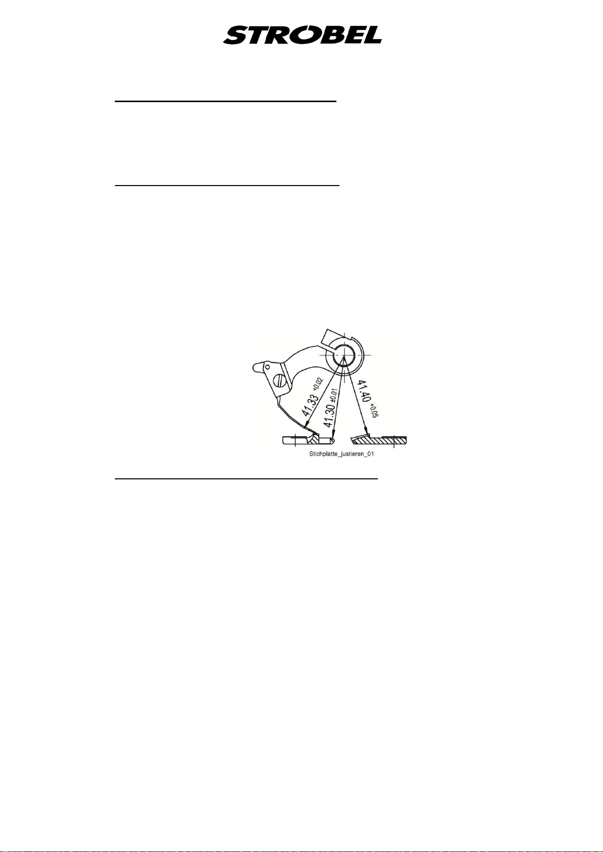
2.5 Theoretic needle radius: 41.3 mm
Abridged version of adjustment manual
Left needle guide: 41.33 +0.02 mm
Needle glide plate: 41.30 ±0.01 mm
Right needle guide: 41.40 +0.05 mm
Needle stroke, needle eye to looper finger: 1.5 +0.5 mm
Ball pin to needle shaft: 4 ±0.5 mm
Slot ball pin: approx. 15°
Looper stroke: 18 +0.5 mm
Pressures:
Feed plate: left 12 N
right 12 N
Cloth support arm: 140 N (meas. at presser shaft)
Plunger limit stop: 6 N
Feed length: approx. 5 - 8 mm
Lifting between needle plate
and feed plates: approx. 13 mm
Lifting between needle
and plunger: approx. 10 mm
Loop stroke: 2.8 +0.3 mm
Number of spot tacks 2 – 4 stitches

10 MA_VEB100-3_A2_181015_en
3
Notes on repair and adjustments
CAUTION! Injury hazard!
Read the safety and operating instructions before
performing maintenance and/or repair work. Failure to
comply with them can lead to severe bodily injury.
3.1
Needle plate assembly
CAUTION! Injury hazard!
Switch off the machine electrically!
Needle plates are adjusted at the factory and can be easily exchanged in their
entirety. When replacing needle guide(s), the adjusting dimensions must be
rechecked using a dial gauge. After removing the needle lever, the dial gauge is
inserted into the needle shaft and, by turning the handwheel, touches the
surface of the needle guide.
3.1.1 1. Switch off machine electrically, cloth support arm is lifted.
Removing the needle plate (Fig. 1)
2. Remove needle and needle lever.
3. Remove the thread trimmer's drive unit as described under “3.8.1
Removing and remounting of the thread trimmer drive (Fig. 15)” or pull the
plug only.
4. Release needle plate fastening screws (1) and (2) and remove the
complete needle plate unit to the front.

11 MA_VEB100-3_A2_181015_en
Fig. 1
12 MA_VEB100-3_A2_181015_en
3.1.2 Remount the needle plate in reversed order but make sure that the needle plate
opening is mounted centrically to the presser foot and that the needle plate is
mounted horizontally. Push the needle plate bow completely upwards until
threaded pin (3) fits closely to the needle shaft bush.
Installing the needle plate (Fig. 1)
3.1.3 At the left needle guide, the theoretical needle radius of 41.3 mm should be
0.03 to 0.05 mm larger. At the needle slide plate, it should be 0.01 mm smaller
to 0.01 mm larger and at the right needle guide it should be 0.06 to 0.08 mm
larger.
Adjusting the needle plate (Fig. 2)
The adjustment must be made using a dial gauge. Deviations lead to
significantly poorer sewing results and may even cause preliminary damage or
wear to the sewing tools.
Fig. 2
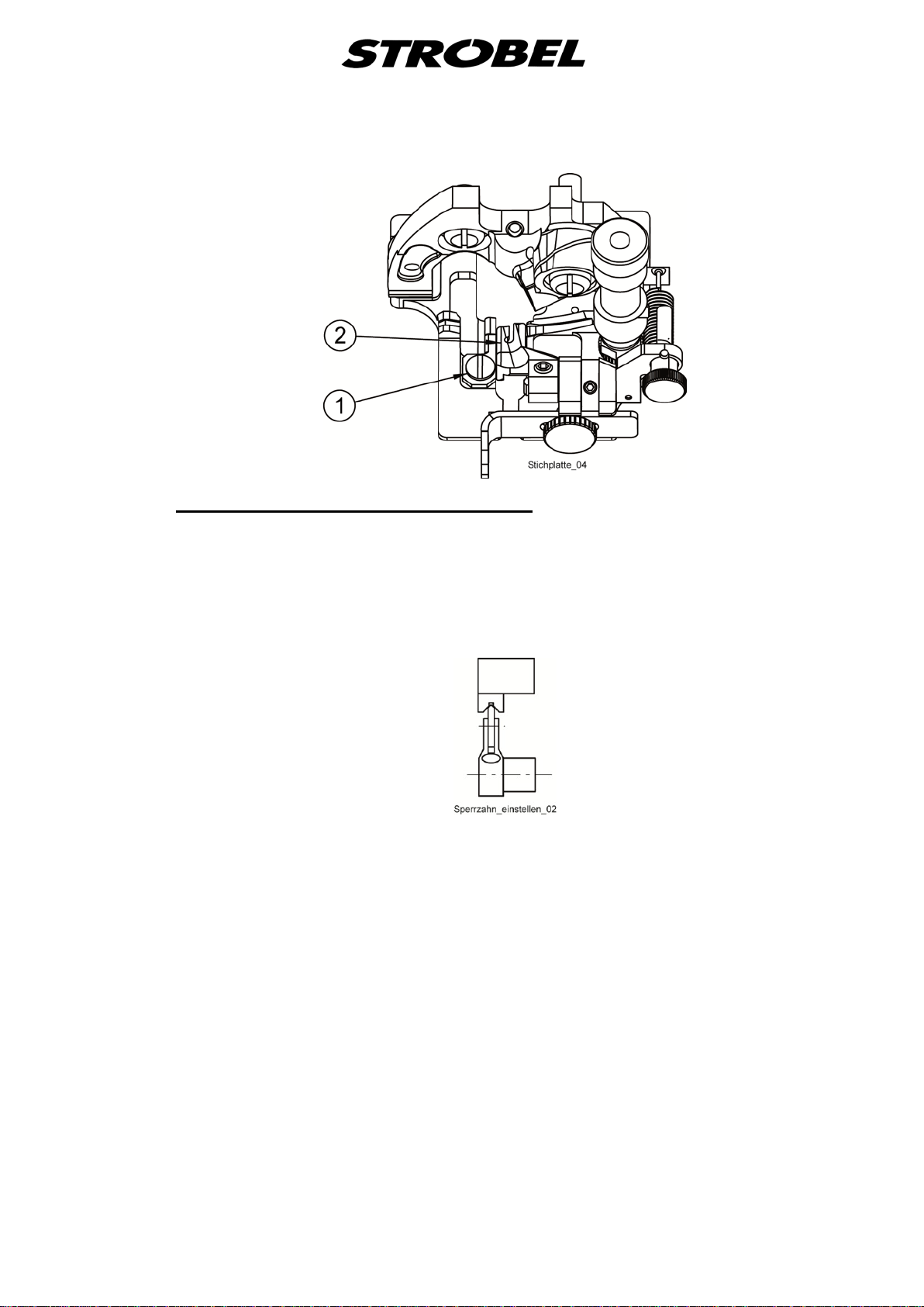
3.1.4 The needle slide plate on the central base of the needle plate can be removed
after loosening the screw (1).
Replacing the needle slide plate (Fig. 3)
When assembling, ensure that the needle slide plate lies firmly against the base.
13 MA_VEB100-3_A2_181015_en
Fig. 3
3.1.5 After replacing the needle plate, check whether the cloth retainer
Adjusting the cloth retainer (Fig. 4)
(2) Fig. 3 lies
centrally on the plunger. This is particularly important for roof-shaped
plungers/cloth retainers to ensure that the material is optimally held during
sewing.
Fig. 4

14 MA_VEB100-3_A2_181015_en
3.2
3.2.1 Needle lever
Assembly
CAUTION!
Switch off the machine electrically!
Remove screw (10) Fig. 6, move the Thread take-up lever and remove the
needle lever. During installation, please ensure that the needle runs through the
centre of the needle groove and the needle tip is flush with the left needle guide
(Fig. 5).
Fig. 5
15 MA_VEB100-3_A2_181015_en
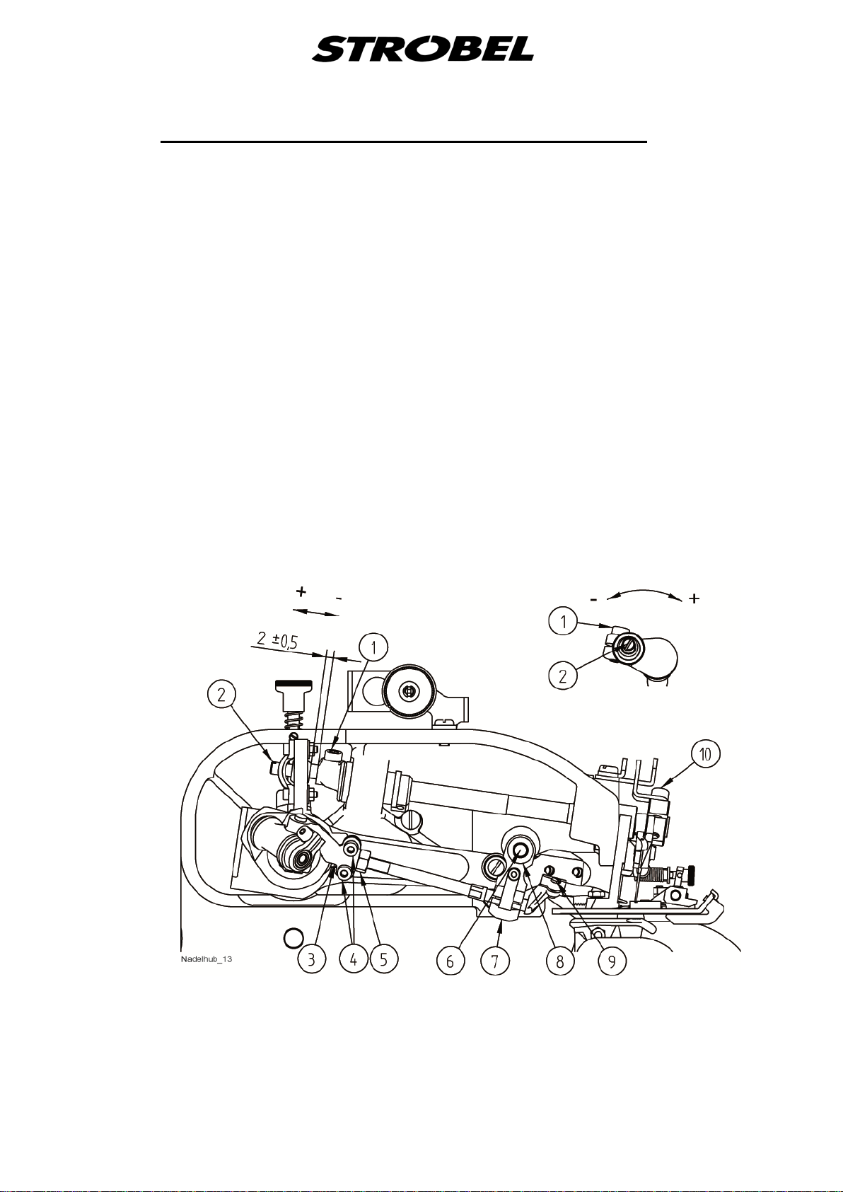
3.2.2 For a loop stroke of 2.3–3.0 mm, the needle stroke must be set to that the left
side of the needle’s eye is approx. 1.0 +0.5 mm away from the large gripping
finger when the tip of the large gripping finger is above the centre of the needle
(
Adjusting the needle stroke (Fig. 6, Fig. 7 and Fig. 9)
Fig. 9).
The head cover must be removed for the adjustment. After removing (hex key
size 4) screw (1) shown in Fig. 7, the ball pin (2) shown in Fig. 6can be
adjusted using a slotted screwdriver.
In the horizontal position, insert the ball pin so that the slot of the ø6 bolt stands
vertically beneath the ø7 bolt.
Rotating it clockwise will result in a larger needle stroke while turning it in the
opposite direction will create a smaller needle stroke.
The distance between the ball pin and needle shaft is 2 ±0.5 mm. After
adjusting the needle stroke, the needle lever must be configured as described in
section “3.2.1 Assembly”.
Tighten the screw (1) shown in Fig. 7.
Check the looper and needle movement by turning the main shaft using the
handwheel.
Fig. 6

16 MA_VEB100-3_A2_181015_en
Fig. 7
Other manuals for VEB100-3
2
Table of contents
Other Strobel Industrial Equipment manuals

Popular Industrial Equipment manuals by other brands

SCHUNK
SCHUNK ERT 12 Assembly and operating manual

SMC Networks
SMC Networks CS2 Operation manual

ABB
ABB HT587622 Operation manual

Pentair
Pentair Aurora 1080 Series INSTRUCTION, INSTALLATION, MAINTENANCE AND REPAIR MANUAL

SCHUNK
SCHUNK TENDO Platinum Assembly and operating manual

ABB
ABB HT609828 Operation manual

CNC Router Parts
CNC Router Parts CRP2448 Assembly instructions

Honeywell
Honeywell Industrial HERMetic Sampler GTX Chem Operation and service manual

Agil Elektronik
Agil Elektronik eFuse 2-200-10 instruction manual

Hiwin
Hiwin KK Assembly instructions

Hirobo
Hirobo FL-II Assembly

Team
Team SILK FXB630 instruction manual


