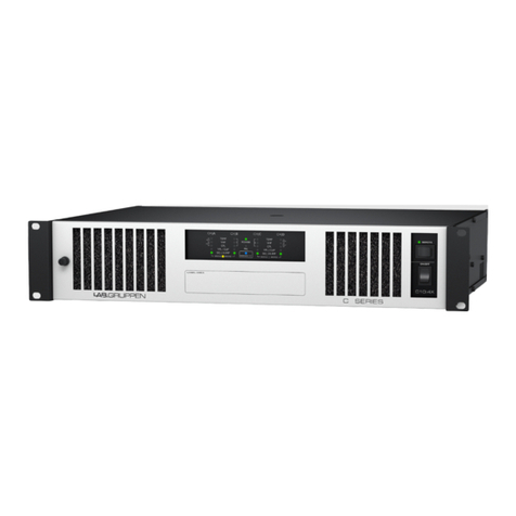
Stromberg-Carlson APH-1100 Manual

STROMBERG-CARLSON®
niodel
APH-1100
100
watt
audio
power
amplifier
SPECIFICATIONS
OUTPUT
POWER
-
100
watts
with
less
than
5%
harmonic
distortion
from
50-15,
000
cps,
80
watts
with
less
than
2%
harmonic
distortion
from
40-20,
000
cps.
FREQUENCY
RESPONSE
-
20-30,
000
cps
±
ldb,
high
pass
filter
"out"
10-70,
000
cps
±4db,
high
pass
filter
"out"
IM
DISTORTION
-
3.
5%
maximL1m
with
4:1
ratio
of
60
cps
and
7KC
INPUT
SENSITIVITY
-1.
volts
into
250, 000
ohms
un-
balanced;
. 5
volts
into
10,
000
ohms
balanced
line
HUM AND NOISE -SOdb
below
100
watts
REGULATION
INPUTS
-
Full
load
to
no
load
less
than
2db
-One
input;
amplifier
may
be
operated
with
a 250K
ohm
unbalanced
input
or,
when
an
input
transformer
is
used
with
a lOK
ohm
balanced
input
GIIIIIIIID
GENERAL
CJVNAMICS
OUTPUT
CONTROLS
-70V
and
25V
center
tapped
constant
voltage
line
and
115V
aulio
output
receptacle.
-
Input
level
control,
DC
balance
and
Bias
Adjustment
Controls
POWER
SOURCE -
105-125
volts
AC,
50-60
cps
POWER
CONSUMPTION-·
175
watts
TUBE
AND DIODE
COMPLEMENT
1 - 7199
2 -
6550
2-1Nl764
1 -
1Nl873
Voltage
amplifier
and
phase
splitter
Power
Outputs
Rectifiers
(full
wave)
Bias
Supply
Rectifier
ACCESSORIES
Standby
Relay
-
172000-015,
Model
No.
RS-1012
Input
Transformer
-
172000-065,
Model
No.
TB-1011
Hinge
Kit
-
SC-1102
Amplifier
Panel
-
SCP-1101
ELECTRONICS
ROCHESTER
146011-204
.....
=
Ol
e+-
~
.....
.....
~
e+-
.....
0
=

GENERAL
DESCRIPTION
The
APH-1100
is
a
high
quality,
100
watt
amplifier
de-
signed
for
use
in
school
systems
and
in
commercial
rack
and
shelf
mounted
applications.
Rack
mounting
of
this
unit
may
be
facilitated
by
the
use
of
an
accessory
hinge
kit
(SC-1102)
containing
a
hinged
bracket
for
use
in
pro-
viding
the
amplifier
with
a
"swing
out
for
service"
feature.
An
amplifier
panel
with
pilot
light
opening
(SCP-1101)
is
also
available
for
rack
mounting.
A
standby
relay,
Model
No.
RS-1012
(Part
no.
172000-
015),
can
be
accomodated
by
the
relay
socket
provided
on
the
amplifier
chassis.
Twenty
four
volts
DC (24 VDC)
applied
to
terminals
Kl
and
K2
will
energize
the
relay
and
ground
the
cathodes
of
the
output
tubes,
placing
the
amplifier
in
its
"ready"
mode
of
operation.
The
APH-1100
has
a
high
impedance
(250K
ohm)
un-
balanced
input
with
provision
for
the
installation
of
an
input
matching
transformer,
Model
No.
TB-1011
(part
no.
172000-065).
This
accessory
will
provide
isolation
from
the
input
source
and
permit
balanced
operation
from
a
source
of
lOK
ohms
or
less.
SERVICE
INFORMATION
Power
Transformer
The
power
transformer
of
the
APH-1100
features
a
tapped
primary
winding
for
either
117V
or
125V
operation.
Connections
for
the
two
voltage
ranges
are
as
follows-
White
lead
common,
Black
and
White
lead
117V
tap,
Black
lead
125V
tap.
All
amplifiers
shipped
from
the
factory
will
be
connected
for
125
volt
operation.
Should
the
line
voltage
in
your
locality
be
consistently
below
125
volts
reconnect
to
the
117V
tap.
Input
Transformers
Inputs
with
an
impedance
of
lOK
ohms
may
be
impedance
matched
to
the
amplifier
by
the
addition
ofan
input
trans-
former
172000-065
which
plugs
into
the
socket
provided
on
the
amplifier
chassis.
NOTE:
Before
installing
this
transformer
remove
the
plug-in
jumper
between
pins
3
and
4
of
the
socket.
If
an
unbalanced
high
impedance
input
is
to
be
connected
to
the
amplifier
the
transformer
must
be
removed
and
the
jumper
reinserted.
As
many
as
four
(4)
APH-1100
amplifiers
may
be
oper-
ated
in
parallel
from
either
the
Stromberg-Carlson
SCP-
1003
or
SCP-1005
preamplifier.
Standby
Relays
A
Standby
Relay,
172000-015,
available
as
an
accessory,
may
be
used
as
an
output
tube
cut-off
to
place
the
ampli-
fier
in
its
"standby"
mode.
Before
installing
the
Standby
Relay
the
plug-in
jumper
between
pins
5
and
6
of
the
relay
socket
(on
amplifier)
must
be
removed.
If,
at
any
time,
the
Standby
Relay
is
removed
this
jumper
must
be
reinserted.
Once
the
relay
is
installed
twenty
four
(24)
volts
DC
ap-
plied
to
terminals
Kl
and
K2 on
the
amplifier
terminal
strip
will
energize
the
relay
and
apply
a
ground
to
the
cathodes
of
the
output
tubes,
placing
the
amplifier
in
its
"ready"
mode.
CONTROLS
AND
ADJUSTMENTS
Power
Output
Stage
Bias
Adjustment
-
DC
Balance
Controls
The
Bias
Adjustment
Control
provides
a
sufficient
degree
of
adjustment
to
allow
the
employment
of
unmatched
output
tubes
in
the
Power
Output
stage.
The
use
of
matched
pairs
of
output
tubes
however,
will
aid
in
bias
adjustment
and
provide
optimum
conditions
for
high
fi-
delity
output
and
peak
power.
Occasionally,
it
will
be
found
that
some
tubes
cannot
be
balanced
regardless
of
the
Bias
Adjustment
Control
setting;
when
this
occurs
replace
one
or
b6th
of
the
tubes
in
a
push
pull
pair
until
balance
is
obtained.
The
DC
Balance
Control
is
provided
to
allow
readjustment
of
the
amount
of
Plate
Current
in
the
output
stages
of
the
amplifier.
The
Bias
Adjustment
and
DC
Balance
Controls
have
been
adjusted
at
the
factory.
Should
further
adjustment
be-
come
necessary
they
should
be
adjusted
as
indicated
be-
low:
1.
Open
the
shorting
links
on
the
test
point
termi-
nals.
2.
3.
4.
5.
Prior
to
switching
the
amplifier
ON,
turn
the
Bias
Control
to
its
full
counter
clockwise
position.
Switch
ON
the
power
and
adjust
line
voltage
to
125
volts.
NOTE:
The
source
voltage
must
be
exactly
125 V. A.
C.
at
60
cps
and
provided
by
a
vari-
able
voltage
AC
source.
With
no
signal
applied
to
the
amplifier
input
conn~ct
a
voltmeter
(use
a
meter
with
a
DC
scale
capable
of
accurately
indicating
. 55
volts
DC)
between
test
points
A
and
B
and
B
and
C.
Adjust
the
DC
balance
until
equal
voltages
are
measured
between
each
test
point
(A
to B
and
B to
C).
If
a
zero
center
meter
is
available
connect
it
between
test
points
A
and
C
and
adjust
the
DC
Balance
Con-
trol
for
a
zero
reading
on
the
meter.
Reconnect
meter
to
test
point
A
or
C
and
chassis
ground.
Adjust
bias
control
for
• 55
volts
DC.

6.
If
necessary
readjust
the
DC
Balance
Con-
trol
until
• 55
volts
DC
is
measured
from
both
test
points
A
and
C
to
chassis.
Input
level
control
R3
is
a
500K
ohm
potentiometer
which
regulates
the
amplifier
output
by
attenuating
the
input
signal.
Rated
Load
Impedance
for
100
Watts
Output
Rated
Load
-
ohms
50
6.25
LOAD
IMPEDANCE
Rated
Output
-
voltage
70V
25V
The
use
of
line
matching
transformers
is
not
required
when
the
amplifier
output
feeds
a
single
speaker
or
is
divided
equally
among
a few
speakers
spaced
along
a
relatively
short
line.
The
accompanying
chart,
based
on
a
ldb
loss,
indicates
the
maximum
length
of
wire
to
be
used
with
a
specific
wire
size
and
impedance.
When
two
or
more
separate
speaker
lines
are
brought
to
an
ampli-
fier
choose
the
minimum
wire
size
for
each
line
sepa-
rately,
using
the
impedance
which
terminates
that
line.
OUTPUT
TERMINALS
A
O.:i?~~-'
"
GRD
.
70V4+t- ·
2sv...,..·
~1111!!1
CT---:~
25V
.
70V~\'..
Kl
,,
..
K2
[i.
. 0
/.
p~~
;;_~:~<a.~.
s,i@~-@1
11
0N
11
r8>lff
'"jl
sw1tcv-~
FUSE
115V
AUDIO
OUT
PILOT
LAMP
Wire
Line
Impedance
in
Ohms
Gauge
4 8
16
45
22 20
40
80 220
20 30 65
103
350
19 40 80
160
425
18 50 100
200
550
16 80 160 320 900
Wire
Gauge
78 156 312 625
22
400
800
1600
3200
20 500 1000
2000
4000
19
650
1300
2600 5200
18
800
1600
3200 6400
16 1200 2400
4800
--
Should
it
prove
necessary
to
provide
an
uneven
distri-
bution
of
audio
power
to a
number
of
speakers,
the
consta_nt
voltage
line
taps
(70
and
25
volts)
of
the
ampli-
fier
are
to
be
used.
By
connecting
line
matching
trans-
formers
to
each
speaker
it
is
possible
to
provide
the
desired
power
to
each
speaker
position.
The
total
power
drawn,
however,
is
not
to
exceed
the
rated
power
output
of
the
power
amplifier.
INPUT
TRANS.L
VEL
CONTROL
TEST
POINTS
''A"
7199

'
~
REPLACEMENT
PARTS
R3
R12,
R25
fl21
C3
C4
C5
ClO
Cll
C12
CRl,
CR2
SCHEMATIC
CPS
~
~
Resistors
Control,
Vol.
500K
Control,
Dual
Bias,
5K
Resistor,
10
ohm,
15W
Capacitors
50uf/3V
Elec.,
4uf/150V
Elec.,
120uf/350/80uf/200/
20uf/350V
Elec.,
120uf/350V
Elec.,
80uf/200V
Elec.,
50uf/50V
/50uf/50V
Diodes
Rectifier
(Plate
Supply)
"'
_47K
T2
PLUG
IN
TRANSFORMER
(
OPTJONAL)
R2
470K
c,o
120/350
CSA
ca
120/350
c"
80/200
CSB
t::.
80/200
R2 2
47
II
GE
1847
R23
47
CR3,
CR4
145000-136
CR5
145000-137
554567-100
Tl
T2
553088-500
111000-050
111000-111
111000-114
1'11000-115
111000-118
S2
Sl
162000-065
GENERAL
DYNAMICS
I ELECTRONICS
ROCHESTER
STROMBERG
-
CARLSON@
MODEL
NO.APH-1100
AMPLIFIER
VIB
B4V
1/2
7199
91V
•
41V
4/150
C6
47
R6
c,
R4
10%
50/3
470
IMEG
RB
5%
47K
300V
'"
R5.
-C5CO
470
20/350
Rectifier
(Screen
Supply)
Rectifier
(Bias
Supply)
Miscellaneous
Transformer,
Output
Transformer,
Power
Fuse
Holder
AC
Cord
Jumper,
Plug-in
Foot,
Chassis
Socket,
Pilot
Lamp
Socket,
Octal
GP
Socket,
Octal
LL
Switch
DPDT
Switch
AC
.
Lens,
Pilot
Socket,
9
Pin
Rl5
635V
*
6.BK
,.325V
*
2-
WHEN
BALANCED
10K
OHM
INPUT
IS
OESl~EO
REMOVE
JUMPER
FROM:
IN.PUT
iRANS
SOCKET
AND l~SER·T
!R:ANS
.(
G. D.#1610_00 -
065
J•
3-.ALL;
C~Pl;ICl·"'fORS:-rN,
MFO·:uNL(ss
OTHE"Rwfsf
SPECfF.I_E~.±.
20_%;
__
-~
·...' - · :
,------,
I I
I I
4-
ALL
RE·s1si:O,R_s
_tN'OtiMS,
112
w±
10_%
tiNLEss·
OTHERWISE·
.SPECIFIE·o_.
.-
. I I
162000-063
162000-052
161000-188
161000-240
559996-102
117000-026
120000-062
131000-001
152000-072
15201_4-000
152668-000
158000-058
158000-183
559996:-071
559999-028
5-VOLTAGES
ARE±20%"AND
M·us"r
BE
MEASURED
~~I~Ai:sv"!R~~
SJ~N.AL.
*·
INDICATES.
~
I :
L
_______
_J
PLUG
IN
STANDBY
RELAY
(
OPTIONAL
)
PLl.jG
JN
JUMPER
-SEE
NOTE
I
I
STANDBY
RELAY
I
CR5
R25
R2'l
-'lOV
5K
3.9K
Cl2A~
R26
50/50
+ 12 K
Cl28
+
50/50
D
5·-
~bfis;E~~
~~lt\~~NK:IA~N~OUJN~~~
...
~as
tig~T;L
-~~~~~r;~o~s
AND
B
ANO
C
THEN
REPLACE
LINKS.
7 - TO
OBTAIN
115
VOLT
OUTPUT
PLACE
JUMPER
FROM GRO
TO
THE
ADJACENT
70
V TERM
ON
OUTPUT
TERMINAL
BOARD.
8 -
SEE
INSTRUCTION
MANUAL
FOR
ADDITIONAL
INFORMATION
9 -
c::::::::J
INDICATES
EQUIPMENT
MARKING•
•
I-
WHEN REMOTE OPERATION IS
DESIRED,
REMOVE
JUMPER
FROM STANDBY
RELAY
SOCKET
ANO
INSERT
RELAY
{G.0.#172000-015).
PRINTED
IN
THE
u'.S.A.
Other Stromberg-Carlson Amplifier manuals
