Structure Cycleworks SCW1 User manual
OWNERS MANUAL

Welcome
Congratulations on your purchase of a new Structure Cycleworks
SCW1, welcome to our family. Undoubtedly you are eager to throw
a leg over and blast down your favorite trails, but before you do so
take the time necessary to properly build and test your bike before
aiming it down those paths.
Here we have a walk-through of how to unpack and assemble the
full linkage chassis to ride ready condition. If you feel that you are
not up to the task or are missing important tools (torque wrenches,
hose cutters, etc.) be sure to bring it to your favorite local bicycle
shop to have one of their professionals do it for you. No judgment –
pro riders rarely wrench on their own rigs.
WITHOUT TELESCOPING FORK (WTF) LINKAGE SUSPENSION
Structure’s linkage front suspension is designed to be similar to
rear linkage suspension. It uses the same 17mm colleted axles as the
rear suspension at all main pivots and the same 6903 30mm sealed
cartridge bearings, which can be found at most bicycle shops.
The front and rear shock absorbers are identical in design. However,
the front shock includes three volume spacers in the positive
air chamber and requires approximately 65% of the air pressure
required for the rear shock (due to the greater load placed on rear
suspension). Follow the shock absorber manufacturer’s instructions
for shock service intervals, service instructions, and setup.
2

Table of Contents
Safety.................................................................................................. 4
-Components....................................................................................... 5
Overview
-Torque Specications ......................................................................... 6
-Spare Parts ........................................................................................ 8
-Specications ................................................................................... 10
-General Service and Care................................................................ 11
Assembly
-Unboxing and Basic Assembly......................................................... 12
-Suspension Shock Set-up Chart ...................................................... 13
-Internal Cable/Hose Routing .......................................................14-16
Maintenance
-Colleted Axles Removal And Installation.......................................... 19
-Bearing Replacement....................................................................... 19
-Brake Dive Reduction Eccentric Position......................................... 20
-Spherical Bearing Replacement....................................................... 21
Maintenance
-Schedule .......................................................................................... 22
-Warranty........................................................................................... 23
3

Safety
• WARNING
Keep this manual handy for reference.
It is strongly recommended that you follow Structure Cycleworks’ and
component manufacturers’ instructions where indicated in this manual,
as many tasks should only be performed by a bicycle repair technician.
Adhere to all torque and sizing specications. Over-tightening can
damage threads or cause parts to fail. Using the wrong size part can
cause part failure and may cause a crash, which can result in serious
injury or death.
More than most machines, a mountain bike is subject to wear and
high stresses. Various materials and components react to wear and
stress in different ways and may suddenly fail and cause a crash,
which can result in serious injury or death. Any form of scratch, crack,
unusual noise, dent, ber delamination, or change in colouring can
indicate that a component should be inspected by dealer service
personnel and/or replaced before riding.
In the event of an impact or crash, damage to carbon ber
components or frame may be invisible. Consult your dealer service
department immediately for inspection.
Your bicycle requires regular maintenance, frequent inspection, and
timely replacement of parts to address any issues.
Excessive vibration or noise from the wheels, pivots, or frame
indicates a serious problem. Stop riding immediately and consult
your dealer.
Do not expose your bicycle to temperatures of 65°C (150°F)
or higher. High temperatures can damage carbon ber resin or
frame joints.
Do not attempt to repair damaged carbon ber components. Contact
Structure Cycleworks customer service for crash replacement if
necessary. Repairing a carbon ber frame component can compromise
safety and will void the warranty.
Do not place your hands near a moving wheel or drive train
components. A spinning wheel can catch your hand between the
spokes and frame and crush, pinch, or lacerate your hand. Areas
where the chain contacts sprockets can pinch and cause injury, and
sprocket teeth and brake rotors have sharp edges that can cut.
Wear appropriate PPE (personal protective equipment) when cutting,
drilling, using chemicals, or performing other tasks than may expose
you to harm while working on a bicycle.
4

Components
We outline the basics of installation for each the components
included on a complete bike purchase. If you nd these
instructions hard to follow or need a more step-by-step guide go
to the manufacturers website and download the PDF or follow
the online instructions or video.
Full instructions on all components available on the following
websites:
dvosuspension.com
oneupcomponents.com
magura.com
sram.com
• WARNING
Please follow component manufacturer’s installation, torque, and
adjustment instructions for each component. Failure to do so
may result in component malfunction, injury, or death.
5
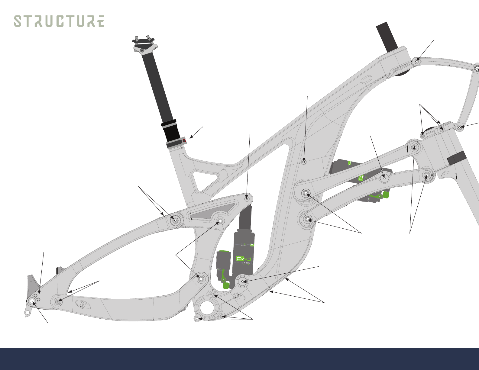
Seat Clamp Bolt
4 Nm Shock Bolt
6 Nm
Shock Bolt
6 Nm
Derailleur Hanger Bolts
3 Nm
Through Axle Bolt
10 Nm
Horst Link Bolts
4 Nm
Collet Retention
8mm Bolts
7 Nm
Seatstay to Rocker Bolts
10 Nm
ISCG Bolts
5 Nm
Battery Cover Bolts
1 Nm
Trunnion Bolts
10-11 Nm
Upper Steering Plate Bolt
6 Nm
Triple Clamp Bolts
5 Nm
Trunnion Bolts
10-11 Nm
Colleted Axle Bolts
Hand tight then 3 Nm
Torque Spec.
6
Through Axle Bolt
10 Nm
Spherical Bearing Bolt
12 Nm
Lower Steering Plate Bolt
6 Nm
Steering Linkage to Side
Bearings Bolts
6 Nm
Other Torque Spec.
Headset preload 5mm Hex 3 Nm
Seat rail clamp bolts 5mm Hex 8 Nm
Remote bar clamp 3mm Hex 1 Nm
Remote cable clamp 3mm Hex 3 Nm
Remote body to clamp 4mm Hex 3 Nm
Stem top bar bolts 4mm Hex Until no gap
Stem bottom bar bolts 4mm Hex 6 Nm
Stem steerer bolts 5mm Hex 9 Nm
Grips 3mm Hex 2 Nm
Brakes:
Bar clamp top bolt T25 Until no gap
Bar clamp bottom bolt T25 4 Nm
Calipers T25 6 Nm
Rotor bolts T25 4 Nm
Banjo bolt loosen 30˚ max T25 30˚
Banjo bolt tighten T25 3 Nm
Sleeve nut 8mm wrench 4 Nm
Drive train:
Cassette Lock ring tool Hand thread then 40 Nm
Shifter mount T25 or 4mm Hex 2 Nm
Rear derailleur 5mm Hex 11 Nm
Derailleur cable T25 or 4mm Hex 4.5 Nm
Bottom bracket Cups 12 notch tool 50 Nm
Crank set 8mm Hex 54 Nm
BB preload on crank 2mm Hex Until ends touch
Pedals Pedal specic tool 54 Nm or mfg. spec.
7
58
1
57
6
51
1
55
1
49
6
50
2
45
2
47
4
46
12
56
3
28
6
29
6
54
4
44
4
57
6
16
2
37
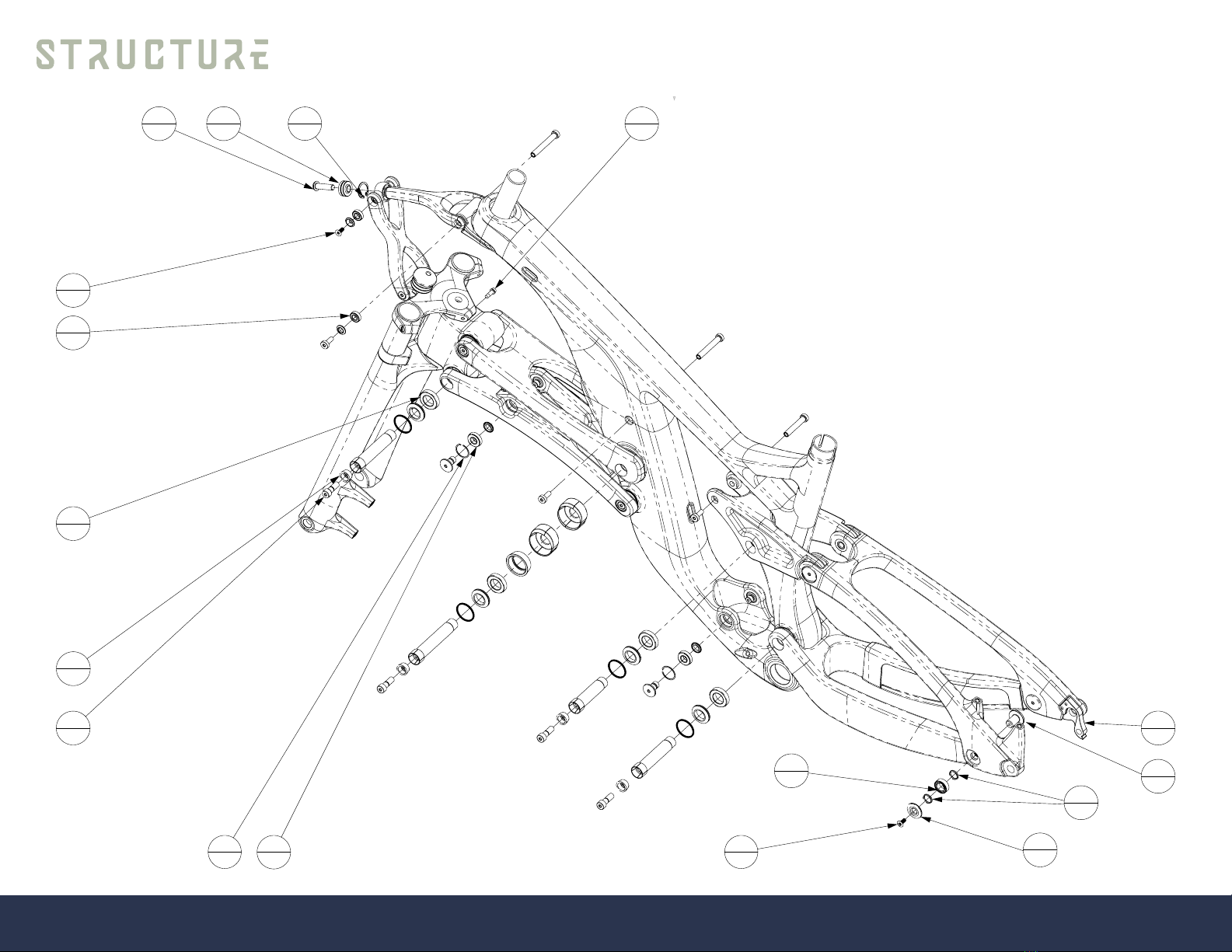
1
Spare Parts
8

Most Common Spare Parts Listing and Number on Bike
#Part Number Description QTY
16 KQS 3791 Pivot bolt, rear triangle 2
28 KQS 2723 Collet washer 6
29 KQS 3785 Bolt Collet M8 6
37 KQS 3550 Rear derailleur hanger 1
44 KQS 3793 Bearing spacer, rear triangle 4
45 KQS 3792 Horst link pivot washer 2
46 6903-2RS Bearing 6903 12
47 6900-2RS Bearing 6902 4
48 3802-2RS Bearing 15x24x7 2
49 688-2RS Bearing 688 6
50 3801-B-2RS-TVH Bearing 3801 2
51 COM-M8T Spherical bearing, 22mm OD x 8mm bore x 12mm wide ball 1
55 98394A440 Internal Retaining Ring, 22mm ID 1
56 BN15857 M5 x 15 Stem Bolt 3
57 BN3803 M5 x 0.8 x 12 Flat Head Cap Screw - T25 Driver 6
58 BN6404 M8 x 1.25 x 30 Button Head Cap Screw 1
59 BN15857 M4 x 0.7 x 12 Socket Head Cap Screw 2
9
Specications
Frame-fork-set Details
Frame/Fork Carbon ber, including fork, linkages and rear triangle
Travel 153mm front / 154mm rear
Wheel size 27.5” (650b)
Tire clearance 2.6” with generous mud clearance
Hardware 17mm colleted aluminum through-axles, machined and engraved 7075 triple clamp
Shocks (2) DVO Topaz / T3AIR custom tuned / 205x65 Trunnion mount
Headsets (2) Cane Creek / 40 series
Axles Boost 15 x 110 mm GW Twist Lever front / 12 x 148 mm stealth rear
Bearings high precision sealed cartridge: 6903 Main pivots / 6902 Trunnion end bearing / 3802 Rocker-seat / 688 Steering link pivots /
22x8x9 Spherical - Teon-coated stainless
Chain line Boost 52 mm (also non-Boost compatible)
Chain ring clearance 34 T Boost / 32 T non-Boost
Front derailleur Single-ring only / chain guide & bash guard compatible
Chain guide mounts ISCG-05
Bottom bracket BSA
Seat post clamp 36.0 mm / Alloy clamp included
Seat post diameter 31.6 mm
Seat post stroke 150mm (G1), 180mm (G2), 210mm (G3)
Cable routing Internal, sleeved / Di2 compatible, wire guides and internal battery mount
Derailleur hanger Replaceable
Brake mounts 203 mm post front / 180 mm post rear
Water bottle mount G1-G3 1 under frame at Di2 battery cover - G3 size has mount in main triangle for 16oz side load bottle
10

General Service and Care
STORING
Store your bicycle where it will not be an obstacle and with protection
from the elements. Do not park your bicycle near electric motors;
ozone from motors can damage rubber and paint. Rain or snow can
cause the metal on your bicycle to corrode. Ultraviolet radiation
from the sun can fade the paint and crack the rubber or plastic on
your bicycle. Before you put away your bicycle for an extended time,
clean and service it and apply frame polish. Hang your bicycle off the
ground with the tires at approximately half the recommended ination
pressure. Before you ride your bicycle again, be sure it operates
correctly.
MAINTENANCE
Bicycle service requires special knowledge and tools and should be
performed by a professional bicycle mechanic. This user manual is to
be used in conjunction with the manuals supplied by the component
manufacturers. If you did not receive the manual provided by the
component manufacturer, download the materials off the Internet
or contact your local dealer. Consult your local dealer to create a
maintenance plan and refer to the Maintenance Schedule on the next
page as a guide for frequent inspection, service, and replacement of
parts.
INCIDENTAL DAMAGE
Do not let your bicycle fall. Do not set your bicycle down with the
frame or derailleur touching the ground. Use care with car racks and
work stands. Clamping devices, such as those found on a work stand
or car carrier, can cause damage to the paint or tubes of bicycle
frames. To hold the bicycle for repairs, clamp the seat post. To hold
the bicycle for transportation on a motor vehicle, clamp the bicycle
by the wheels or fork. If you accidentally apply a bending force to the
fork, do not ride the bicycle until your retailer has inspected the fork
for damage. The nish, or paint, on your bicycle can be damaged by
chemicals (including some sports drinks) or abrasive contact. Dirt can
scratch or remove paint (and even frame material), especially where a
cable rubs or a strap is placed around a tube. Keep the bicycle clean.
Use adhesive padding to prevent rubbing in critical spots.
CLEANING
Clean your bicycle with a soft, moist cloth and bicycle cleaner or a
solution of dish soap and water. Do not use industrial solvents or harsh
chemicals that can damage the paint or moving parts. Do not use
high-pressure water. Every three months, clean and polish the frame
nish. Some nishes do not require polish. If you are not certain,
consult your retailer.
TRANSPORT
When packaging your bicycle for travel, use a hard case or carton
that will protect it from damage. Attach padding to all the frame and
fork tubes, and use a rigid block to protect the fork tips and maintain
structural support of the fork blades. If the bicycle is not packaged
correctly, it could be easily damaged in transit. If you are not sure, ask
your retailer to package your bicycle for you.
11

Assembly
Tools required
1 – T25 Torx tool
1 – T30 Torx tool
1 – ball end hex tool set with 2.5, 3, 4, 5, 6, 8, and
10-millimeter drivers
1 – cassette tool
1 – 24mm socket and ratchet for above
1 – torque wrench, 3-20 Nm range
1 – torque wrench, 20-80 Nm range
1 – brake bleed kit with royal blood (blue mineral oil)
1 – hydraulic hose cutter
1 – cable cutter
Unbox bike frame, fork, and parts bags. Lay out on a soft surface.
Locate shocks and depressurize by depressing Schrader valve. Remove
retention o-ring at the piston end of the main air canister. Holding the
top of the shock, twist and push the outer canister cover down. Insert
3 volume spacers into the positive air chamber of the front shock and
3 volume spacers into the positive air chamber of the rear shock, per
DVO’s instructions. Without pinching the o-ring that separates positive
and negative air chambers, carefully slide the cover back into position
until fully seated and replace o-ring.
The SCW1 is delivered with three volume spacers in the positive air
chamber of the front shock and three in the rear shock. This allows for
plush, responsive small-bump compliance in early in the travel, with
strong resistance to bottom-out. If you determine that you would like
to change the number of volume spacers in your DVO shocks, please
follow DVO’s instructions found on their website.
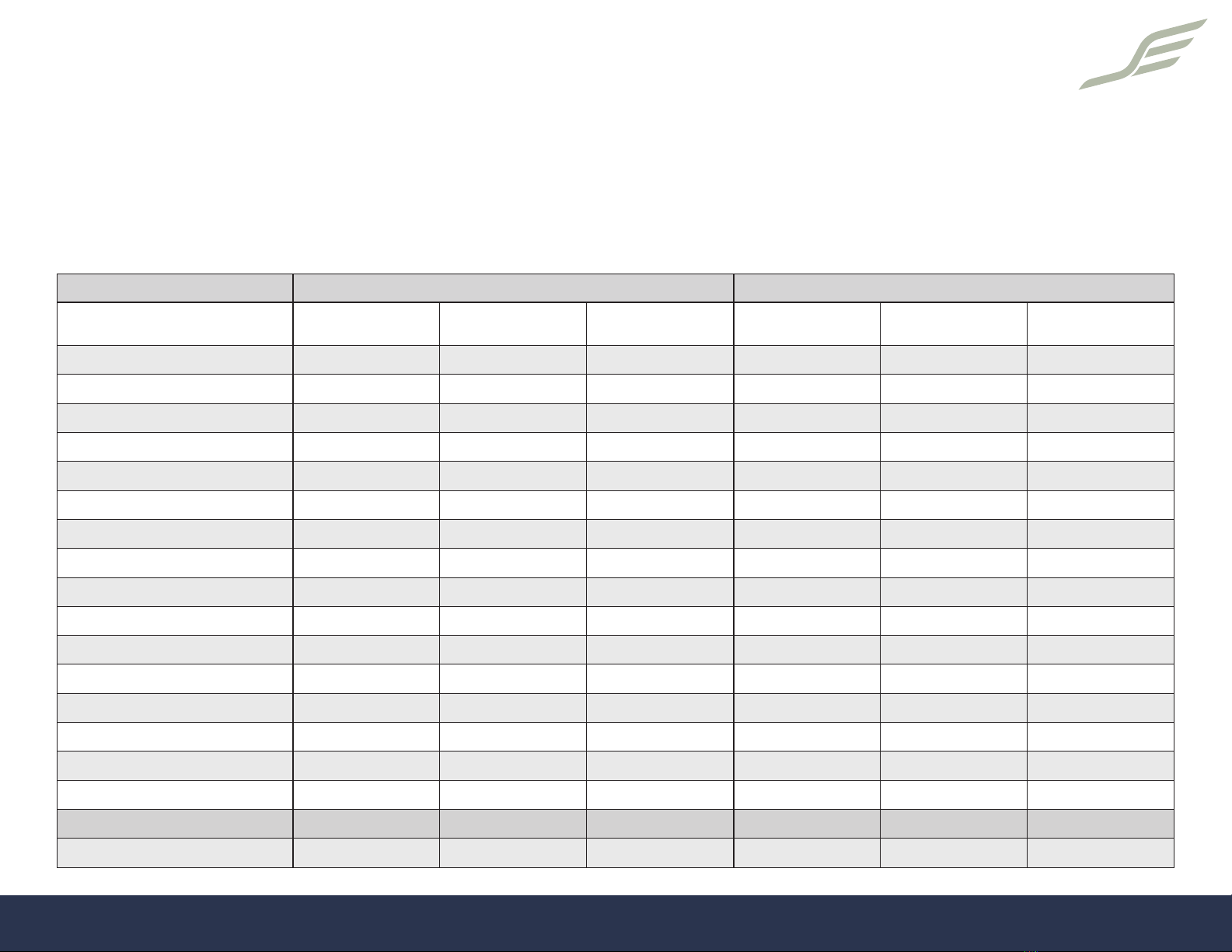
Please refer to the accompanying graph as a chart to setting shock
pressures as a starting point according to riding style. ¢
Locate shock fasteners and bearing washers, place washers (with
smaller taper toward the trunnion(upper eyelet) bearing’s inner race)
against bearing, then hold them in place by putting the trunnion bolt
through the bearing from the outside, just far enough to hold the
washer.
NOTE: For rear shock only, it is best to have trunnion end fully
installed and tightened before fastening small end. Align the shock
with chamber down and wiggle the trunnion end between both
spacer washers until one of the bolts engages threads in the shock
body. Start threading one side and then the other side an ensure both
trunnion end bolts are engaging threads smoothly. Torque to 10-
11Nm. Repeat for the other shock.
For shock small end(lower eyelet), use DVO 8mm x 30mm tment kit,
installed according to DVO instructions. Work the shock’s small end
into position, then install 8mm female bolt from the drive side with a
small amount of assembly grease on the outside surface. Install male
bolt with medium thread locker. While holding male bolt with T30
Torx driver, from the drive side of the bike apply 6 Nm of torque to
the female bolt only.
Locate fork, steering linkage, headsets and stem. Install the bumpers
onto the fork making sure the ats align (moisture will help slide
them on). Set aside crown races (unnecessary). Install lower headset
bearings at both upper and lower steering heads, using a plastic dead-
blow hammer (if necessary) to gently seat the bearings. Place fork
12
into lower steering head and install top headset bearing and split race
on top of fork steerer tube (for fork only, set aside top cap, as it will
not be used).
On the steering linkage, loosen all three cinch bolts on the triple
clamp and carefully slide the triple clamp over the three tops of the
fork. Install headset top cap and bolt and tighten until bearings are
engaged but not overly tight (4 Nm). Fold and/or rotate linkage to
Rider Weight, With Gear Rear Shock Front Shock
(lbs) Plush
(3 vol. spacers) Aggressive
(2 vol. spacer) Bike Park Jump (2
vol. spacers) Plush
(3 vol. spacers) Aggressive
(3 vol. spacers) Bike Park Jump (3
vol. spacers)
100 90 95 100 55 60 65
110 99 105 110 61 66 72
120 108 114 120 66 72 78
130 117 124 130 72 78 85
140 126 133 140 77 84 91
150 135 143 150 83 90 98
160 144 152 160 88 96 104
170 153 162 170 94 102 111
180 162 171 180 99 108 117
190 171 181 190 105 114 124
200 180 190 200 110 120 130
210 189 200 210 116 126 137
220 198 209 220 121 132 143
230 207 219 230 127 138 150
240 216 228 240 132 144 156
250 225 238 250 138 150 163
Compression (min/med/max) min min med min min med
Rebound (clicks from 0) +6 +5 +6 +6 +5 +6
13
correctly orient the links before installing the upper steerer through
the main frame headset. Install top cover, making sure split ring is in
place. Using assorted 5mm and 10mm steerer spacers to set desired
stem height, install the stem on the steerer.
Tighten preload cap to set headset preload, applying no more than
4Nm of torque. Set preload on lower headset in the same manner,
using no more than 4Nm of torque. Once the fork and steering
assembly rotate smoothly – without looseness or play in either steerer
– tighten stem bolts per stem manufacturer’s torque specication;
then add thread locker and tighten triple clamp bolts to 7 Nm. Go over
all of the fasteners in the steering system a second time to conrm
correct torque at each fastener.
Using a non-marring tool, carefully pry out the two front rubber cable
outlets, starting from a bottom corner. Slowly work the rubber cable
outlet out of the frame.
Locate seat post collar and place it on the frame with bolt forward
and the reading upright. Locate seat post and lever/cable kit. Apply
assembly grease to the inside of the frame set through the hole in the
bottom bracket shell to facilitate sliding of the cable housing past the
tight radius at the bottom bracket.
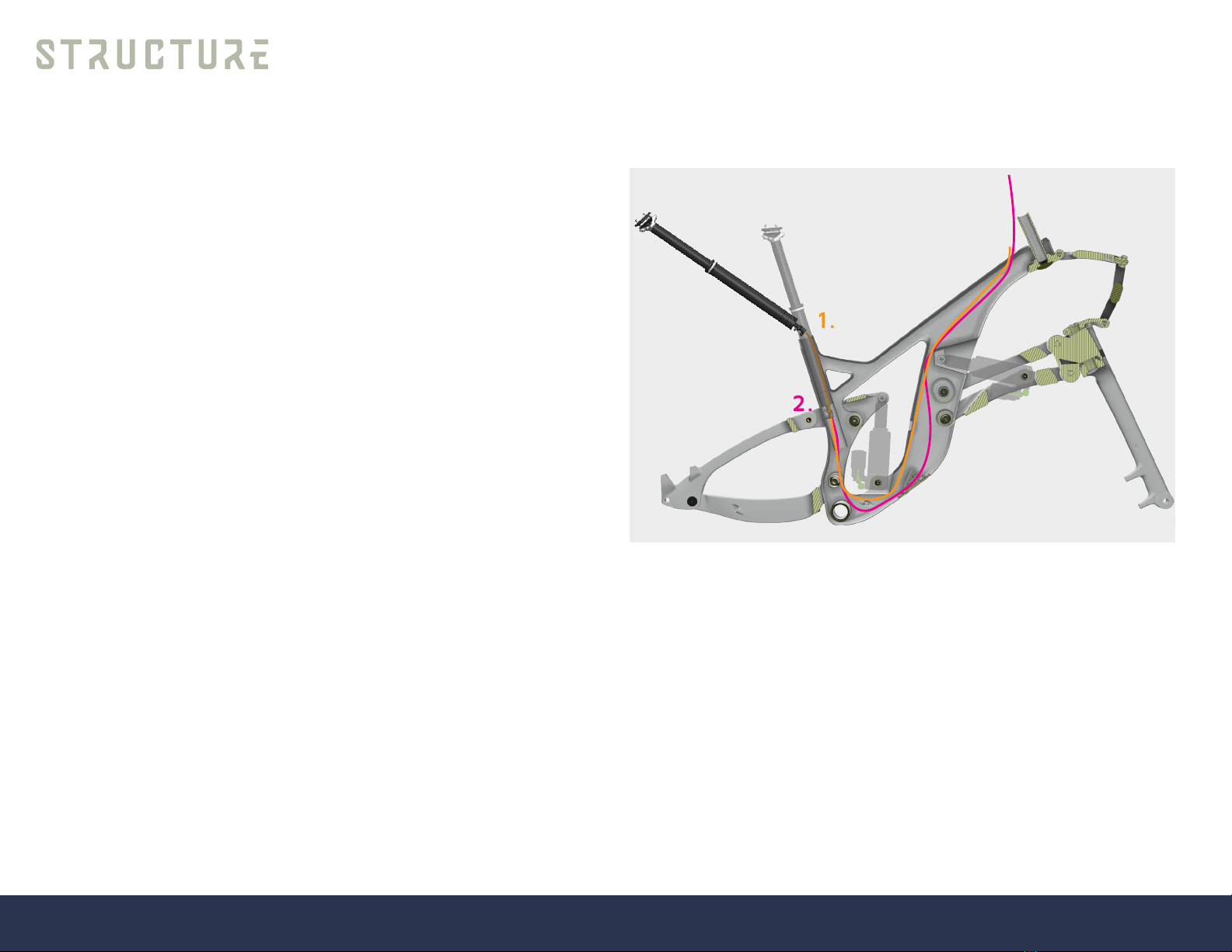
Install the cable housing from the top of the seat tube, guiding it past
the front of the chain stay pivot to the hole in the frame’s bottom
bracket shell. With one nger, guide the cable housing forward to feed
it across to the Di2 battery opening in the bottom of the down tube.
Push until it extends out of the battery opening, pulling through until
20mm remains above the seat collar.
Feed end at battery port through one of the smaller foam silencing
tubes and then up into the frame. Aim the cable housing to the space
in the down tube behind the front shock pocket and continue feeding
the housing until it becomes visible at the cable outlets in the top
tube.
Use a spoke or wire with a small hook in the end to grab the housing
and pull it through the non-drive side cable exit, remembering to twist
the loop at the battery opening to straighten the cable housing in the
frame. Install the supplied cable barrel onto the cable.
1.
2.
w
¢
¢
14
Attach cable to seat post actuator, place a ferrule on the seat post end
of the housing and feed the cable into the housing until snug, grab the
cable at the front of the bike pushing the housing back and ease the
seat post into the frame while pulling the cable and housing out the
front.
Tighten the seat post clamp to 4 Nm and then clamp the bike onto
the stand by the seat post. Remove saddle clamps to access Schrader
valve on top of seat post; attach shock pump and pressurize to 275
psi. Replace clamps and attach the seat. Now you may attach the
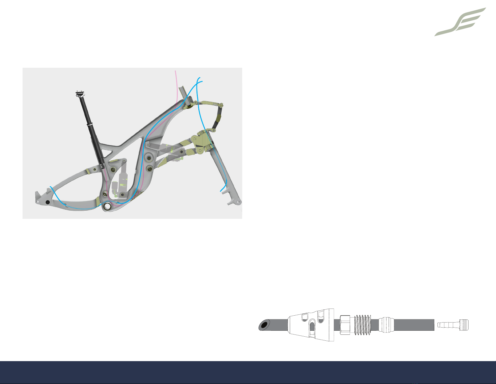
handlebar to the stem. Locate the brakes, front and rear will have
different length hoses. For the front brake, disconnect the hose at
the lever. Placing the lever on the bar with the open end up, slide the
cover and sleeve bolt back. Using a utility blade or hose cutter, cut
the hose behind the olive and insert a hose plug. Then insert the hose
end into the fork leg until it comes out the top hole and loosely bolt
the caliper to the fork.
Slightly loosen the banjo bolt and rotate the hose to an optimal
position and re-tighten to 3Nm (27 in-lb) Determine the hose length
for the front brake, ensuring that it is not long enough to contact
the upper steering link when the suspension is fully compressed. Cut
the hose and slide on cover, bolt and olive. Grip the hose using two
transport devices and insert barb into hose end. Slide olive and sleeve
nut forward and reconnect the hose to the lever by hand while a
steadily pushing the hose into the lever to assure proper crimping of
the olive. Torque sleeve nut to 4Nm (35 in-lb) Disconnect hose from
rear brake lever, slide cover and sleeve bolt back, cut hose below the
olive, and insert a hose plug. Insert the hose on the non-drive-side
lower stay, feed until it comes out the front outside of the stay, then
feed directly into the main chassis. Guide the hose out the battery
port and loosely attach the caliper to the frame.
Slide the 6mm foam dampening cover onto the extended hose, then
loop back into the frame and guide against the rear of the down
tube until you feel it reach the top tube; slowly feed until it is visible
through the right hand port and use a hook to pull it out and route it
through one of the two drive-side cable guide holes. Slightly loosen
the banjo bolt and rotate the hose to an optimal position and re-
tighten to 3Nm (27 in-lb).
w
¢
¢
¢
¢
¢
15

w
¢
¢
¢
16

Determine the hose length for the rear brake after rotating the
handlebar bumper to bumper. Cut the hose and slide on cover, bolt
and olive. Grip the hose using two transport devices, insert barb into
hose end, slide olive and sleeve nut forward and reconnect the hose
to the lever by hand while pushing hose steadily into the lever, then
torque sleeve nut to 4Nm (35 in-lb)
Drive train - Locate the shifter, derailleur, and shifter housing.
Starting at the drive side port in the chain stay near the derailleur,
slide the shifter housing through to the front of the chain stay, pulling
it until only enough housing is exposed to reach the derailleur, then
guide the forward end into the frame opening adjacent to the upper
ISCG-5 tabs. Find the housing as it reaches the Di2 port and guide
the forward end out of the port. Slice the remaining 5mm silencing
sleeve over the housing and guide the forward end up into the frame
past the rear of the front shock opening until the forward end can be
hooked and pulled out of the drive side cable port.
Attach shifter to the bar with a 5mm hex socket and derailleur to the
hanger and torque to 11 N-m (97 in-lb). Fit a ferrule to the shifter
end of the housing and guide the housing into the shifter. Rotating
bars lock to lock to determine the correct amount of housing to leave
between the cable exit and shifter. Pull excess housing through the
frame and then measure the housing to the derailleur. Retract the
cable forward toward the shifter so it is not cut, then cut the housing
to the correct length. Add a ferrule to the derailleur end of the
housing.
Locate bottom bracket and determine drive and non-drive sides, then
thread in as far as you possible by hand. Using an appropriate bottom
bracket socket, torque to 50Nm (443 in-lb).
Insert drive side crank through bottom bracket and tap with soft
mallet until seated. Attach the non-drive side crank with an 8mm
hex by hand, then use a torque wrench to tighten the crank arm bolt
to 54 Nm (478 in-lb). Remove play from the system by turning the
preload adjuster in the + direction until it stops or makes contact with
the bearing shield. Use a 2 mm hex wrench to tighten the bolt until
the adjuster edges touch. Check the cranks et for play by rocking
the crank arms back and forth. There should be no side-to-side play
present.
Pedals - Install the washer between the crank arm and pedal.
Tighten the pedal shaft to 54 Nm (478 in-lb) unless otherwise
specied by the pedal manufacturer. Note that the non-drive side is
reverse threaded.
Wheels – Tighten the rotor bolts in an alternating sequence until
a torque of 6.2 Nm (55 in-lb) is achieved for each bolt. Install the
cassette onto the driver body until it is fully seated with the splines
engaged, then tighten the cassette with a cassette installation tool.
Torque to 40 Nm (354 in-lb).
Tubeless tire setup - Follow the instructions on the sealant product
you’ve purchased.
Install wheels on bike. For the rear wheel, place the rear derailleur
in lock position, place the chain on the smallest cassette cog, and
guide the rotor into the caliper. Insert the axle and with a 5mm hex
key torque to 12.4 Nm (110 in-lb). It is a good idea to get used to the
feel of this torque, as trailside repairs may require removal and re-
installation of the rear wheel.
17

The front wheel uses a QR style through axle. Once wheel is in
position with rotor in caliper, thread the axle until hand tight, then pull
lever outward and align lever arm with fork leg.
Brake centering – Pull and release the lever a couple of times while
helping the caliper center itself. Pull and hold brake lever, then tighten
retaining screws alternately and in stages to torque of 6 Nm (53 in-
lb). Check that wheel spins freely - if necessary, loosen the retaining
screws until caliper can move and repeat the above steps.
With the rear wheel installed - viewing the cassette from the rear of
the bike - adjust the inside adjustment screw on the derailleur (3mm
hex) until the top cog on the derailleur is centered on the outside edge
of the smallest cog on the cassette.
Attach the shift cable to the derailleur, pulling it tight without
deecting the derailleur, and tighten clamp screw to 4.5 Nm (T25 or
4mm hex).
Shift the derailleur to the largest cog using the thumb shifter and
adjust the outside adjustment (3mm hex) screw until the top cog on
the derailleur is centered on the center of the largest cog. Shift back
to the smallest cog and install the chain.
Note: the chain supplied with your bike has been pre-cut to the
correct length. With the rear derailleur still in lock position, feed the
chain from the chain stay over the cassette and into the derailleur –
over the top pulley and under the bottom one. Wrap the chain over
the front chain ring and insert the joiner links onto the ends. Engage
the joiner and lock by holding the wheel and rotating the crank until
the joiner link clicks. Unlock the derailleur by rotating the pulley arm
forward to release, then ease back until the chain is tensioned.
Set up - Test Ride
Now you are ready to throw a leg over and check the setup. Have a
multi tool and with you and roll around near home to adjust handlebar
and control angles, seat height and angle and to check for anything
that might be amiss.
18

Colleted Axle Removal and Installation
Colleted axles are used at all main pivots. To remove an axle, rst
remove the 8mm collet bolt using a T-30 Torx driver. Remove the
tapered collet using an 8mm hex and turn gently by hand until the
collet comes free. The axle itself can then be removed using a 10mm
hex driver.
After removing the axle, swing the suspension arm out of the way
to expose the bearing caps. Remove bearing caps carefully to avoid
damaging the seals. Each of the bearing caps on the main front
and rear linkage bearings includes an x-ring seal. To prevent water
intrusion and creaking due to misalignment of suspension arms with
the bearing cap, it is very important to make sure that the seal on
each bearing cap is fully seated and is not ipped or bulging from its
groove. Carefully and fully seat the seal on each bearing cap before
installing the suspension arm and colleted axle.
To install the axle, ensure that the threads of the axle and suspension
arm are clean and free of contaminants using mild solvent such as
isopropyl alcohol and shop air.
Apply medium strength thread locker to dry threads and tighten the
axle by hand until slight load is placed on the bearings. This is best
felt by hand. It should feel like the axle is just beginning to tighten.
Once slight preload on the bearings is felt, back the axle off and re-
tighten until it feels like the axle is just beginning to tighten and there
is no slack between suspension arms, bearing caps, and bearings. No
additional preload is required. Over-tightening can create noise and
accelerated bearing wear.
Install the axle collet with a smear of grease on the outer surface
to ease future removal. Apply medium strength thread locker to the
threads of the 8mm collet bolt and torque the bolt to 7 Nm.
Bearing Removal and Installation
A bearing puller is recommended for bearing removal. However,
Structure Cycleworks bicycles are designed so that bearings may be
driven out from the opposite side of the frame. If a puller is not used,
to remove a bearing use a plastic dead blow hammer and drive the
bearing out with light, even, alternating taps to opposite sides of the
bearing, taking care to drive the bearing out evenly and avoid damage
to the bearing seat.
To install a bearing, a bearing driver or installation tool is
recommended. Before installing, wipe the bearing seat clean and use
a thin smear of grease on the outer surface of the bearing. While
making sure that the bearing is sitting ush with the outer edge of the
cup, slowly draw the bearing into the cup with the bearing driver until
the bearing is fully seated.
Install the bearing cap, ensuring that the x-ring seal around its
perimeter is fully seated and not twisted or bulging.
• WARNING
If the seal is pinched or bulging, water intrusion, noise, and/or
accelerated bearing wear may occur.
19

Brake Dive Reduction Eccentric Position.
The SCW1 utilizes eccentric bearing housings at the aft end of the
upper front control arm at the down tube. The purpose of the eccentric
housings is to allow selection of one of four dive reduction settings.
Telescoping forks are approximately 30% pro-dive under application
of the front brakes. Structure’s Without Telescoping Fork suspension
system reduces front brake dive by 17% (Plush), 22% (Low), 33%
(High), or 41% (Race), depending on the eccentric housing that is
installed and its orientation up or down.
All SCW1 bikes are delivered to owners with the eccentric in the Plush
(17% dive reduction) setting. To change the amount of front brake
dive reduction, consult the following:
Note that the set of eccentric housings for 17% dive reduction is thin
17% dive reduction position 22% dive reduction position 33% dive reduction position 41% dive reduction position
at the upper edge. This set of eccentrics ips 180° to provide 41% dive
reduction. A separate set of eccentrics (provided to the owner of each
bike) - with a slightly thicker upper edge at 22% than the eccentric for
17% - is used to provide 22% and 33% dive reduction. Make sure to
always use correctly matched pairs of eccentric housings.
When installing the eccentrics, a thin smear of grease is recommended
on the outer surface of the eccentric to ensure ease of removal in the
future.
Ensure that the bearing caps are fully seated and that the x-ring seals
are not twisted or bulging, as improperly seated seals can allow water
penetration to the bearing and may cause excess friction or noise in
the pivot.
20
Table of contents


 Owner's service manual")


 owner's manual")


