Studio Technologies 210 User manual
Copyright © 2008 by Studio Technologies, Inc., all rights reserved
www.studio-tech.com
User Guide
Issue 4, October 2008
This User Guide is applicable for serial numbers:
M210-00415 and later
50311-1008, Issue 4

This page intentionally not left blank.

Model 210 User Guide Issue 4, October 2008
Studio Technologies, Inc. Page 3
Table of Contents
Introduction................................................................... 5
System Features ........................................................... 5
Installation and Setup ................................................... 9
Configuration ................................................................ 14
Operation ...................................................................... 21
Technical Notes............................................................. 25
Specifications................................................................ 34
Appendix A.................................................................... 35
Block Diagram

Issue 4, October 2008 Model 210 User Guide
Page 4 Studio Technologies, Inc.
This page intentionally not left blank.

Model 210 User Guide Issue 4, October 2008
Studio Technologies, Inc. Page 5
Introduction
What This User Guide Covers
This User Guide is designed to assist you
when installing, configuring, and using
the Model 210 Announcer’s Console.
Additional background technical informa-
tion is also provided. A product block dia-
gram is included at the end of this guide.
System Overview
The Model 210 Announcer’s Console is
designed to serve as the audio control
center for announcers, commentators,
and production talent. The tabletop unit is
suited for numerous applications including
on-air television sports broadcasting. The
Model 210 integrates all on-air, talkback,
and cue audio signal routing into one com-
pact system. Ease of use, flexible in con-
figuration, and sonically excellent are some
of the unit’s highlights.
The Model 210 is compatible with most
broadcast and audio system environments.
Standard connectors are used to interface
microphone, headphone, talkback, and IFB
signals. Whether it’s microphone switch-
ing, talkback output, or headphone cue
feed, superior audio quality is maintained
throughout. A microprocessor provides the
Model 210’s logic power, allowing exacting
control of the unit’s operation. A range of
configuration choices allow the desired op-
erating configuration to be easily selected.
While flexible, the user is presented with an
easy-to-use set of controls and indicators.
A truly next-generation product, extensive
research into the needs and desires of field
production personnel was integral to the
Model 210’s creation. While primarily tar-
geted for on-air television applications, spe-
cialized features are included to allow the
Model 210 to be used in a variety of other
audio applications. These include on-air
radio broadcasting, stadium announce-
ment, and voice-over/narration booths.
System Features
Microphone Input
A high-performance microphone
preamplifier circuit provides low-noise/
low-distortion amplification over a 20 to
60 dB gain range. The gain is adjustable
in 10 dB steps. The input is compatible
Figure 2. Model 210 back panel
Figure 1. Model 210 front panel

Issue 4, October 2008 Model 210 User Guide
Page 6 Studio Technologies, Inc.
with balanced dynamic or condenser mi-
crophones. The microphone power source
is 48 volts nominal and meets the world-
wide P48 phantom power standard. An
LED indicator serves as an aid for optimiz-
ing the setting of the preamplifier’s gain.
The output of the microphone preamplifier
is used by the main output as well as be-
ing routed to the compressor circuit that
supports the talkback function.
Main and Talkback Outputs
The Model 210 provides one main and
one talkback output. The main output is
designed to serve as the on-air, stadium
announcement, or other primary audio
feed. Nominally –2 dBu, it is designed
as a fully professional interface with high
output capability, low distortion, and low
noise. It features a high-quality transformer
expressly designed for driving long broad-
cast cable runs. The talkback output is
intended to provide production trucks,
control rooms, or support personnel with a
talent-originated cue signal. The talkback
output is transformer-coupled with a +4
dBu nominal signal level. It contains resis-
tors in series with its output connections,
allowing the talkback output from multiple
units to be directly “summed.”
For non-on-air applications, a special
Model 210 feature can be enabled, plac-
ing the unit in a “production” mode. This
allows the main output to be used as a
second talkback output. In this configura-
tion the unit can be even more powerful
when used in a live event application,
such as serving as a master console for a
production director.
Dynamic Range Control
A studio-quality compressor circuit is pro-
vided to control the dynamic range
of the signal coming from the microphone
preamplifier. Far from a simple “clipper,”
the circuit utilizes a sophisticated laser-
trimmed voltage-controlled-amplifier (VCA)
integrated circuit for quiet, low-distortion
level control. The signal from the compres-
sor is always used by the talkback output.
In addition, the audio source for the main
output can be selected to be either the
output of the microphone preamplifier or
the output of the compressor. While possi-
bly not appropriate for major on-air situa-
tions, having dynamic range control of the
main output can offer increased perfor-
mance for many applications. These could
include stadium announcement positions,
sports events using nonprofessional on-air
talent, and situations where cable cross-
talk is of concern.
User Controls and Status
Indicators
Two pushbutton switches, three LED indi-
cators, and two rotary controls provide
the user with a clear, easy-to-use interface.
One pushbutton switch controls the status
of the main output. This is the audio out-
put intended for on-air, announcement, or
other primary uses. Two LEDs display the
on/off status of the main output. A second
pushbutton switch controls the status
of the talkback output. This is the audio
output used to communicate with produc-
ers, directors, spotters, or other behind-
the-scenes production personnel. A status
LED is associated with the talkback but-
ton. Two rotary controls allow the user to
adjust the level of the headphone output.
Flexibility
A large part of the Model 210’s unique
power is the ability to configure the
operation of the main output and

Model 210 User Guide Issue 4, October 2008
Studio Technologies, Inc. Page 7
talkback functions. To meet the needs
of the many specific broadcast and pro-
duction applications, a variety of button
operating modes is available. The main
output button can be selected to operate
from among four modes. In the “push-to-
mute” mode the button performs a mo-
mentary mute of the main output. In this
way a “cough” button function is created,
something typically required for television
sports broadcasting. In the “push-to-talk”
mode the button provides a momentary
active function for the main output. This
mode would be appropriate for applica-
tions such as stadium announcement. An
alternate action “latching” configuration
allows the button to enable or disable the
main output as desired. This is useful in
radio broadcasting, announce-booth, or
voice-over applications. The fourth mode
provides a hybrid function, supporting
both push-to-talk and tap-to-enable/
tap-to-disable operation. This operation
is similar to that found in many broadcast
intercom system user stations.
The button associated with the talkback
function can be configured to operate
from either of two modes. One of the
modes supports a “push-to-talk” function.
This is typically used for on-air broadcast
applications. The other mode provides
a hybrid function, the operation of which is
discussed in the previous paragraph. The
hybrid mode is especially useful when the
Model 210 is used in a production-support
application.
IFB Input
A broadcast-standard “wet” (DC with au-
dio) IFB circuit can be directly connected
to the Model 210’s IFB input. Originated
by sources such as the RTS™ 4000-series
IFB system or IFB interface devices from
Studio Technologies, the connected IFB
circuit can provide DC power to operate
the Model 210 as well as two channels of
cue audio.
Cue Sources
The Model 210 allows the two IFB audio
sources to be selected for routing to the
headphone output. Originating in produc-
tion trailers, control rooms, or remote loca-
tions, these unbalanced sources normally
provide DC power and program-with-
interrupt audio on one channel and pro-
gram-only audio on the other. Each source
can be individually assigned to the left
channel, right channel, or both left and
right. This allows a wide variety of stereo
and mono headphone mixes to be created.
Some applications may benefit by being
able to connect standard line-level audio
signals to the Model 210. To meet this need
one or two optional line input cards can
be installed in the Model 210’s back panel.
Each card provides a female XLR-type con-
nector and transformer-isolated +4 dBu
nominal input circuit. Each source can be
individually assigned to the left channel,
right channel, or both left and right.
Headphone Output
Two rotary controls are provided for user
adjustment of the headphone output levels.
For application flexibility the actual function
of the two “pots” is configurable. For tradi-
tional on-air sports applications they can be
selected to the dual-channel (“level/level”)
mode which provides independent con-
trol of the left- and right-channel volume.
For use with dual-channel cue signals,
or to support user preference, the stereo
(“level/balance”) mode can be selected. In
this mode one control adjusts the overall
level of both the left and right channels,

Issue 4, October 2008 Model 210 User Guide
Page 8 Studio Technologies, Inc.
while the other allows adjustment of the
left/right level balance. To help minimize
the chance of broadcast cues being
missed, both level control modes can be
configured so that a minimum headphone
output level is maintained. Alternately, the
headphone output can be set to fully mute
when the controls are at their minimum
position.
Provision has been made to support ap-
plications where a monaural cue feed is
desired. A configuration switch allows the
summing (combining) of the selected left
and right headphone sources. In addition
to creating a dual-channel mono output it
also allows the level controls to be config-
ured as a simple 2-channel mixer.
The headphone output was designed
to meet the needs of contemporary head-
phones and headsets. Specifically, the
output circuits act as voltage, rather than
power, drivers. In this configuration they
can provide high output levels with very
low distortion and noise, along with mini-
mal current consumption. The output cir-
cuits are configured to safely drive stereo
or mono loads. This ensures that all types
of headphones, headsets, and earpieces
can be directly connected.
Audio Quality and Protection
The Model 210’s circuitry is carefully
tailored to provide excellent audio perfor-
mance. Professional-quality components
are featured throughout. For reliability
all audio routing is performed using solid-
state devices. In all critical audio paths,
“clickless” electronic switches provide
noise-free control. All audio inputs and
outputs make extensive use of protection
components. This limits the chance of
damage from ESD and other undesirable,
yet real-world, hazards.
Power Sources
The Model 210 can derive its operat-
ing power from either the IFB input or an
external nominal 24 volt DC source. For
redundancy, both power sources can be
connected simultaneously. An internal
switch-mode power supply ensures that
all Model 210 features are available when
the unit is powered by either source.
The Model 210 is compatible with IFB
circuits provided by most standard broad-
cast systems. However, maximum perfor-
mance can often be obtained by using the
IFB interface devices available from Studio
Technologies. Single-channel and four-
channel units are available, each providing
high-quality audio along with an excellent
source of DC power. They’re directly com-
patible with most matrix intercom systems,
as well as standard line-level audio signals.
Refer to the Studio Technologies website
for details.
Configuration
Model 210 configurations are made us-
ing a number of DIP-type switches. One
8-position switch array is used to set the
gain of the microphone preamplifier, the
on/off status of phantom power, and the
headphone stereo/mono mode. Another
8-position switch array configures which
of the IFB audio sources is routed to the
headphone output. A third 8-position switch
array communicates the desired operating
modes to the microprocessor. All switches
are accessible via the bottom of the Model
210’s enclosure; the unit does not have to
be disassembled. Changes made to any
of the configuration parameters become
active immediately. To prevent access to
the configuration switches a security panel,
included with each unit, is attached to the
bottom of the enclosure.

Model 210 User Guide Issue 4, October 2008
Studio Technologies, Inc. Page 9
Connectors
The Model 210 uses standard connectors
throughout. The microphone and IFB inputs
use 3-pin female XLR-type connectors.
The main and talkback outputs use 3-pin
male XLRs. A ¼-inch 3-conductor jack is
used for the headphone output. The ex-
ternal source of 24 volt DC power is con-
nected by way of a 2.1 x 5.5 mm “locking”
coaxial power jack.
In the world of broadcast and produc-
tion audio it’s fair to say that applications
vary widely. To this end, one or two addi-
tional XLR-type connectors can easily be
mounted into the Model 210’s back panel.
Multiple 3-position “headers” located on the
Model 210’s circuit board provide techni-
cian-access to all input and output connec-
tions. Using a factory-available interface
cable kit allows a Model 210 to be opti-
mized to meet the exact needs of specific
applications. For example, some applica-
tions may prefer to use a multi-pin XLR-type
connector to interface with a headset. This
can easily be accomplished by adding the
appropriate 5-, 6-, or 7-pin XLR-type con-
nector and making a few simple connec-
tions. Other applications may benefit from
having “mult” or “loop-through” connec-
tions, something easily incorporated into a
Model 210. One or two optional line input
cards, as previously discussed, can also
be mounted in the spare XLR positions.
200-Series Announcer
Console Products
The Model 210 is just one in a series of
announcer console products available from
Studio Technologies. For applications that
require an alternate set of features the other
products in the 200-series should be re-
viewed. Complete information is available
on the Studio Technologies website.
Installation and
Setup
In this section interconnections will be
made using the input and output con-
nectors located on the Model 210’s back
panel. Microphone input, IFB input, main
output, and talkback output signals are
interfaced by way of 3-pin XLR-type con-
nectors. A ¼-inch 3-conductor phone
jack is provided for the headphone output.
A 2.1 x 5.5 mm coaxial jack allows con-
nection of an external 24 volt DC power
source.
System Components
Included in the shipping carton are the fol-
lowing: Model 210 Announcer’s Console,
user guide, button label sheet, and 24 volt
DC power supply. For units shipped to
destinations in Japan and North America
the power supply will have a nominal AC
mains input of 120 volts. For all other des-
tinations a power supply compatible with
220/240 volt AC mains will be included.
Microphone Input
The Model 210 is compatible with bal-
anced dynamic and condenser micro-
phones. Depending on the application,
the microphone may be part of a headset,
or be an independent handheld or stand-
mounted model. The Model 210’s 48 volt
nominal power source will support essen-
tially all phantom-powered microphones.
The quality of the Model 210’s microphone
preamplifier and associated circuitry is
such that special applications may benefit
from using “high-end” microphones. If
selected appropriately, models from man-
ufacturers such as AKG, Beyer, Neumann,
Sennheiser, and Shure will perform very
well in Model 210 applications.

Issue 4, October 2008 Model 210 User Guide
Page 10 Studio Technologies, Inc.
Microphone interconnection is made by
way of a 3-pin female XLR-type connec-
tor which is located on the Model 210’s
back panel. The mating connector (male)
should be wired so that pin 2 is signal
high (+ or hot), pin 3 is signal low (– or
cold), and pin 1 is shield. It’s possible that
an unbalanced microphone will also work
correctly. In this case, the mating connec-
tor (male) should be wired so that pin 2
is signal high (+ or hot), and signal com-
mon/shield is connected to both pins 1
and 3.
The Model 210 is not compatible with
unbalanced “electret”-type microphones
that require a source of low-voltage DC
for operation. These microphones, some-
times found in low-cost headsets, are
not generally suitable for on-air or other
demanding applications.
As of the writing date of this user guide,
the Sennheiser HMD25 headset is very
popular for on-air sports broadcasting
use. A fine product, it works very well
with the Model 210. Note that adding the
suffix “-XQ” to the headset’s part number
(HMD25-XQ) specifies a 3-pin male XLR-
type connector for the dynamic micro-
phone and a ¼-inch 3-conductor plug for
the stereo headphones. This configura-
tion is very useful, allowing the headset
to work directly “out of the box” with the
Model 210.
If the writer may digress for a moment
to recount a story… an audio dealer
once shared a secret with me concerning
headsets. He loved selling the “lower-end”
(less expensive) models of name-brand
headsets, which he did by the veritable
“boatload.” Why? Because these usually
broke soon after going into service! He
knew that on a regular basis he’d receive
orders for more of them. Had these
users, from the beginning, purchased only
premium-quality headsets, their total cost
of ownership would have been much less.
Enough said…
Headphone Output
The Model 210’s headphone output is
compatible with stereo or mono head-
phones, headsets, or earpieces. Connect-
ing devices with a nominal impedance
of 100 ohms or greater is preferred. This
shouldn’t prove to be an issue as essen-
tially all contemporary devices already
meet this condition.
Devices are connected to the headphone
output by way of a ¼-inch 3-conductor
phone jack located on the Model 210’s
back panel. As is standard for stereo
headphones, the left channel is connected
to the “tip” lead of the ¼-inch headphone
jack. The right channel is connected to
the “ring” lead of the jack. Common
for both channels is connected to the
“sleeve” lead.
Devices with ¼-inch 2-conductor “mono”
plugs can also be used with the Model
210’s headphone output. In this arrange-
ment only the tip lead (left channel) will
be active. The 2-conductor plug will
physically connect (“short”) the ring lead
(right channel) to the sleeve lead (com-
mon). Technically this won’t damage
the circuitry associated with the right-
channel headphone output. (51 ohm
protection resistors are electrically in
series with the headphone output circuits.)
However energy will be wasted if an au-
dio signal coming out of the right channel
goes into a “dead short.” There is a simple
solution to this issue. No audio source
should be assigned to the right-channel
headphone output. Refer to the Configura-
tion section of this user guide for details.

Model 210 User Guide Issue 4, October 2008
Studio Technologies, Inc. Page 11
Main Output
The main output is intended to be the
“on-air” signal that connects to the input
of an audio console. The output is trans-
former balanced with a nominal signal lev-
el of –2 dBu. The actual level will depend
on the gain setting of the microphone
preamplifier, sensitivity of the microphone,
and how loudly the talent speaks into
the microphone. The transformer used
in the main output is intended for profes-
sional broadcast applications. It has a low
source impedance and can drive lengthy
cable runs with no difficulty. It is capable
of driving 600 ohm loads but performs
best with loads of 2 k ohms or greater.
(This should not prove to be an issue as
virtually all contemporary audio equipment
has a relatively high input impedance.)
As the secondary winding of the output
transformer connects directly to the main
output connector, care should be taken
so that DC voltage is never present on the
interconnecting cable.
The main output is interfaced by means
of a 3-pin male XLR-type connector
located on the Model 210’s back panel.
The interconnecting cable’s mating
connector (female) should be wired so
that signal high (+ or hot) is on pin 2 and
signal low (– or cold) is on pin 3. The
cable’s shield can be connected to pin
1, but it will have no function. To limit the
chance of grounding interaction between
the Model 210 and connected equipment,
pin 1 on the main output’s connector is
isolated from any point in the Model 210.
The fact that pin 1 “floats” will minimize
the chance of hums, noises, or buzzes
being present on the equipment connect-
ed to the main output.
Talkback Output
The talkback output is intended for con-
nection to control rooms, production
trailers, or other locations where talent-
originated voice cues are required. The
talkback output is transformer balanced
with a nominal level of +4 dBu. To en-
hance talkback audio quality, the com-
pressor circuit controls the dynamic range
of the signal coming from the microphone
preamplifier.
For protection against accidental connec-
tion to cables that have DC power present,
the talkback output is capacitor coupled.
In series with the talkback output leads
are 300 ohm resistors, making the ef-
fective output impedance approximately
600 ohms. These resistors create a pas-
sive summing network, allowing talkback
outputs on multiple Model 210 units to be
connected together.
The talkback output is connected by way
of a 3-pin male XLR-type connector which
is located on the Model 210’s back panel.
A mating connector (female) should be
prepared so that signal high (+ or hot) is
expected on pin 2. Signal low (– or cold)
should be expected on pin 3. The cable’s
shield can be connected to pin 1. But,
like the main output, in order to minimize
the chance that ground-interaction prob-
lems will arise, pin 1 of the talkback out-
put connector is isolated from the Model
210’s chassis and circuitry. By making pin
1 “float,” an often-feared “ground loop”
problem shouldn’t arise.
The talkback output is intended to drive
lengthy cable runs that are frequently part
of a remote broadcast application. While
the output circuitry is not intended to be
“on-air” quality, overall audio performance
should be very good. Devices connected

Issue 4, October 2008 Model 210 User Guide
Page 12 Studio Technologies, Inc.
to the talkback output can range from
amplified loudspeakers to analog inputs
on intercom systems, and input channels
associated with audio consoles. Connect-
ing the talkback output to devices that
allow easy control of the signal level can
be helpful. For example, connecting to a
spare input module on an audio console
provides the flexibility to add gain or
attenuate as required. A talkback-
associated output connection on the
audio console can then connect to the
final destination(s).
As previously mentioned, the talkback
outputs on multiple Model 210 units can
be directly connected together. Using
a simple “Y” or “W” cable, this passive
summing (adding together) of talkback
signals allows one audio cable to serve
as a master talkback path. A side effect
from using this passive summing tech-
nique is that signal attenuation will
occur. The audio quality won’t suffer, but
an audio “pad” is created. If two talkback
outputs are connected together, a signal
attenuation of 6 dB can be expected. Con-
necting three talkback outputs together
will result in 9.5 dB of attenuation. And
four talkback outputs “multed” together
will lead to 12 dB of attenuation. In most
cases this attenuation won’t pose a prob-
lem. Typically a device that receives the
talkback signal, such as an amplified
loudspeaker, will have an adjustable input
sensitivity.
IFB Input
The Model 210’s IFB input is designed
to directly connect with “wet” (DC-biased)
IFB circuits. These circuits provide DC
power and one or two channels of audio
over a standard 3-conductor microphone-
style cable. Typically, the IFB circuit’s
interface connector is a 3-pin male
XLR-type wired so that common is on pin 1,
DC with channel 1 audio is on pin 2, and
channel 2 audio is on pin 3. Some IFB
circuits may only have one audio channel.
In this case, audio will generally be on pin 3
with pin 2 providing only DC power.
The power supplied by an IFB circuit,
normally in the range of 28 to 32 volts DC,
is usually sufficient to operate the Model
210’s circuitry. The acceptable input range
is 24 to 32 volts, with a required current of
105 milliamperes. Note that the specified
input voltage is given when measured di-
rectly at the Model 210’s IFB input connec-
tor, not at the source of the IFB circuit. The
one or two audio signals provided by the
IFB circuit can serve as the audio sources
for the headphone outputs.
In North American field and in-studio
broadcast applications it is common to find
RTS 4000-series IFB equipment being used
to provide the IFB circuits. The Model 210
can be directly connected to, and function
correctly with, one of these circuits. For
reliable operation, especially when using
lengthy cable runs, it’s strong-ly recom-
mended that no other device be connected
to a 4000-series IFB circuit that is speci-
fied for connection to a Model 210. This
requirement is due to the current-limited
DC source that is supplied by the 4010 IFB
Controller.
With 4000-series IFB circuits channel 1
(XLR pin 2) provides program audio that is
“interrupted” with cue signals. This channel
is sometimes referred to as “program-with-
interrupt.” It’s important to note that the
program audio source fully mutes whenev-
er directors or producers are communicat-
ing with on-air talent. Channel 2 (XLR pin 3)
of the IFB circuit provides a “program-only”
audio feed. It is never interrupted with cue
signals.

Model 210 User Guide Issue 4, October 2008
Studio Technologies, Inc. Page 13
While the Model 210’s IFB input was
designed for connection to a “wet” IFB
circuit, it’s also possible to connect line-
level audio sources. Please refer to the
Technical Notes section of this user guide
for details.
External Power Input
An external source of 24 volt DC power
can be connected to the Model 210 by
way of a 2.1 x 5.5 mm coaxial power jack
which is located on the back panel of the
unit. The center pin of the jack is the posi-
tive (+) connection. While the requirement
for the external source is nominally 24
volts, correct operation will take place
over a 20 to 30 volt range. The Model 210
requires 70 milliamperes at 24 volts DC
for correct operation. Included with each
Model 210 is a 24 volt DC external power
supply. The power supply’s DC output
cable has been terminated with a Switch-
craft® S760K coaxial power plug. This
“locking” type of plug correctly mates
with the Model 210’s 24 Vdc input jack.
The locking feature is important, allowing
the external power source to be securely
attached to the Model 210.
As previously discussed in this user guide,
an IFB circuit connected to the IFB in-
put can serve as the Model 210’s power
source. Alternately, an external 24 volt
DC source can be connected. For redun-
dancy, both the IFB circuit and the exter-
nal source can be connected at the same
time. If one or the other becomes inopera-
tive, the remaining source will provide all
Model 210 power.
Note that if both an IFB circuit and an
external 24 volt DC source are connected,
power will be drawn only from the exter-
nal source. This minimizes the chance
that lengthy cable runs or other IFB circuit
issues will impact Model 210 operation.
Whichever device is providing power,
audio signals from the IFB circuit can still
serve as the audio sources for the head-
phone output.
Pushbutton Labeling
The two pushbutton switches used in
the Model 210 were selected for several
reasons. Foremost was the fact that they
are highly reliable, using gold-plated con-
tacts for long life in less-than-ideal environ-
ments. A second reason was that applying
customized labels to the button caps
would be very simple. The labels, text
printed on clear material, are placed under
the clear caps on the top of the buttons.
From the factory the left button is labeled
COUGH and the right button is labeled
TALKBACK. This was selected to be
appropriate for many on-air applications
in English-speaking locations. But it’s
expected that these may need to be
changed to meet the needs of specific
applications.
As a “head start” for some applications,
a clear sheet with a number of commonly
used button designations printed on it
is included in the shipping carton. These
were created at the factory using a stan-
dard personal computer graphics program
and laser printed onto 3M CG3300 trans-
parency film. The desired button labels
can be cut out with a pair of scissors, fol-
lowing the printed guide lines that indicate
the required size.
The clear lens on top of each button cap
can be removed with a fingernail or small
screwdriver. Be certain not to scratch the
button if a screwdriver or other small tool
is used. The clear label can be removed
and replaced. The button cap is then

Issue 4, October 2008 Model 210 User Guide
Page 14 Studio Technologies, Inc.
snapped back into the top of the button
housing using finger-pressure only. No
tool is required to replace the button cap.
If you need to make your own labels the
process is quite simple. Use a personal
computer to create the desired text. The
finished label size should be 0.625-inches
(15.8 mm) square. The completed artwork
can then be printed on transparency film
sheets using a laser or inkjet printer. These
sheets are readily available from most
office supply stores. A pair of scissors or
an X-ACTO® knife will complete the task.
Configuration
For the Model 210 to support the needs
of specific applications a number of op-
erating parameters must be configured.
These include microphone preamplifier
gain, phantom power on/off, headphone
source selection, headphone stereo/
mono mode, and operating modes. Three
8-position DIP-type switch assemblies are
used to establish the desired configura-
tion. These switch assemblies are referred
to as SW1, SW2, and SW3, with individual
switches designated as SW1-1, SW1-2,
etc. The switch assemblies are accessed
through openings in the bottom of the
Model 210’s enclosure. The enclosure
does not have to be disassembled to gain
access to the switches.
To prevent unauthorized personnel from
changing the configuration settings, a
security plate is attached to the bottom
of the Model 210’s enclosure. For conve-
nience, attached to the security plate is
a configuration settings label. It provides
a summary of the configurable parameters
and related information. Refer to Ap-
pendix A for a representative view of the
label. The security plate is held in place by
means of four rubber bumpers (“feet”) that
have built-in screws. Using your fingers,
remove the four bumpers so that the plate
can be removed. Refer to Figure 3 for a
detailed view of the configuration switch
assemblies.
Figure 3. Bottom view of Model 210 showing
configuration switches and compressor active
LED
Microphone Preamplifier Gain
and Phantom Power
Five switches are used to set the gain of
the microphone preamplifier. One switch
is used to select the on/off status of the
phantom power supply.
Model 210 User Guide Issue 4, October 2008
Studio Technologies, Inc. Page 15
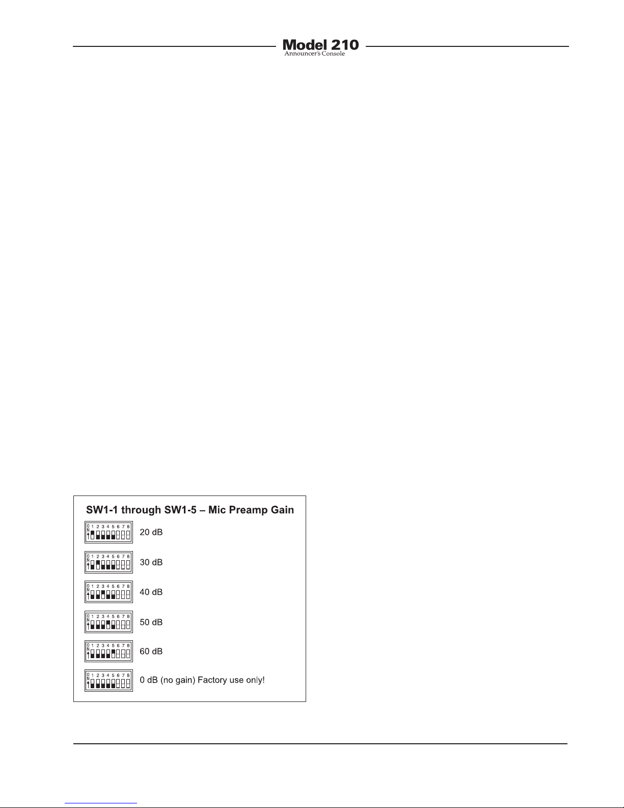
Microphone Preamplifier Gain
Switches SW1-1 through SW1-5 are used
to select the gain of the microphone
preamplifier. The choices are 20, 30, 40,
50, and 60 dB. Only one switch should
be enabled at a time. There’s no problem
changing the gain setting while the unit
is operating. Audio clicks or pops might
occur during gain transitions, but this
shouldn’t be a major issue as long as as-
sociated monitor loudspeakers are tempo-
rarily attenuated or muted.
Selecting the correct amount of gain for an
application might take a little experimenta-
tion. The goal is to bring the mic’s signal
up to line level, nominally –2 dBu for the
Model 210’s main output. Operating at this
signal level will help to ensure the delivery
of “clean” audio to the connected device.
The output of the Model 210’s microphone
preamplifier is used by the main output
and, by way of the compressor circuit, the
talkback outputs. So creating a nice “hot”
signal will help maintain audio quality,
specifically the signal-to-noise ratio, when
driving the often-lengthy cable runs.
Unfortunately, there’s no “perfect” gain
setting that this guide can recommend.
The two issues that impact the setting
are output sensitivity of the connected
microphone and the acoustical output
level of the microphone’s user. With
some headset microphones, such as the
Sennheiser HMD25, selecting an initial
setting of 40 dB is appropriate. Users who
speak loudly might need to have the gain
reduced to 30 dB. Quiet users might need
50 dB of gain.
An LED indicator is provided as an aid
in correctly setting the gain of the micro-
phone preamplifier. Red in color, this LED
is located adjacent to switch assembly 1.
It is visible by observing the bottom of the
Model 210’s enclosure when the security
plate has been removed. Technically, this
red LED lights whenever the compressor
circuitry is controlling the dynamic range
of the signal coming from the microphone
preamplifier. The threshold is set to be
2 dB above the Model 210’s nominal
internal operating level. So a good “rule of
thumb” is to adjust the gain of the micro-
phone preamplifier such that the compres-
sor active LED lights (“flashes”) when the
connected microphone is sending signal
peaks. During normal operation the LED
should not remain fully lit when audio is
present on the mic input.
It’s important to remember that the com-
pressor active LED is used to assist in
setting the gain to the optimal value. It
doesn’t necessarily indicate that the main
output’s signal is being compressed.
Unless specifically configured to perform
otherwise, the output of the compressor
is only used for the talkback output.
It’s expected that the 20 and 60 dB gain
settings will not often be used. But there
are always exceptions and that’s why
Figure 4. Microphone preamplifier gain switch
settings

Issue 4, October 2008 Model 210 User Guide
Page 16 Studio Technologies, Inc.
they were included. It’s possible that
with a very “hot” microphone, such as a
phantom-powered condenser-type, 20 dB
of gain could be correct. It’s also possible
that a microphone with a very low-level
output, such as a ribbon-type, would need
60 dB of gain. But in general, the 30, 40,
and 50 dB gain settings will serve most
applications.
Note that if no gain switch is set to its ac-
tive (on) position the preamplifier will oper-
ate at unity (0 dB) gain. In this mode the
preamplifier remains stable, but is intend-
ed for use only during factory testing. A
valid exception would be where a line-level
signal is connected to the microphone in-
put. This could occur with a special Model
210 application. But with a microphone
connected as the input source one should
never use the 0 dB setting. The issue is
that with no gain added to the microphone
input signal, the relative noise floor on the
main and talkback outputs will be much
too high. These outputs are designed for
handling line-level signals, expecting to
receive the output of the mic preampli-
fier. In conclusion, the 0 dB gain setting
doesn’t highlight a problem, but simply
reflects the unit’s gain structure.
Phantom Power On/Off
The Model 210 can provide 48 volt
phantom power to the microphone input.
Switch SW1-8 controls whether or not
phantom power is active. By phantom
power’s very nature it could be left applied
to the microphone input at all times. But
generally people prefer to turn it off unless
required for a specific microphone.
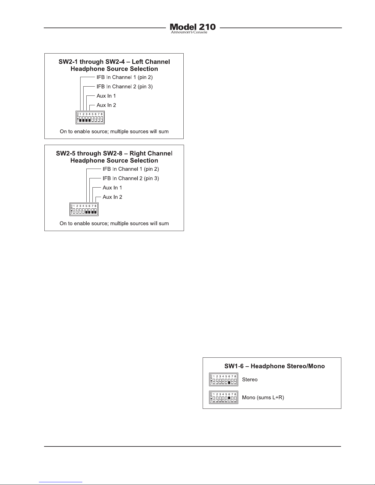
Headphone Source Selection
Switch assembly SW2 is used to configure
the source or sources that are routed to
the stereo headphone output. The head-
phone sources are IFB channel 1, IFB
channel 2, auxiliary input 1, and auxiliary
input 2. The IFB channels are provided by
way of the IFB input connector located on
the Model 210’s back panel. The auxiliary
inputs are available only if the optional
line input cards have been installed or a
special Model 210 configuration has been
implemented.
Each of the available input sources can
be assigned to the headphone output’s
left channel, right channel, or both the
left and right channels. The Model 210’s
circuitry allows any combination of input
assignments to be made. For example,
consider the situation where a single-
channel IFB system, with both program
and interrupt audio on pin 3, is connected
to the Model 210. In this case it may be
desirable to assign this IFB signal to both
the left and right channels. This would en-
tail setting switches SW2-2 and SW2-6 to
their on positions. All other switches would
remain in their off positions.
A more complex application might have
a 2-channel IFB circuit connected to the
Model 210, with an optional line input card
installed and line-level audio from a golf
event “spotter” connected to that. In a
case such as this, it would be typical for
IFB channel 1 to be assigned to the head-
phone’s left channel, IFB channel 2 as-
signed to the right channel, and auxiliary
input 1 also assigned to the right channel.
Figure 5. Phantom power switch settings
Model 210 User Guide Issue 4, October 2008
Studio Technologies, Inc. Page 17
This would allow both IFB channel 2 and
“spotter” audio to be heard in the head-
phone’s right-channel output. To achieve
this would require that switches SW2-1,
SW2-6, and SW2-7 be placed in their on
positions. Note that using another Model
210 at the “spotter” location could also
prove effective. It would provide all the
necessary microphone preamplifier, talk-
back routing, and headphone monitoring
resources.
Note that in some cases a user may
wish to wear a headset or a pair of head-
phones in a left/right orientation opposite
of what’s usual. In this situation the trans-
ducer designated for the left ear would
actually supply audio to the user’s right
ear, and vice versa. A specific application
when this occurs is where on-air talent
needs to have a headset’s boom micro-
phone come across the right side of their
face, rather than the more-typical left side.
In this case it’s important to select the
left- and right-channel headphone source
assignment accordingly. With the Model
210’s flexible source selection there’s no
reason why users, such as on-air talent,
shouldn’t have their cue sources assigned
correctly.
There may be cases where a monaural
“single-muff” headset or headphone will
be connected to the Model 210’s head-
phone output. In this case the desired
source(s) should be routed only to the left
channel. No sources should be assigned
to the right channel. This will eliminate the
short-circuit current that could occur when
a 2-conductor (monaural) plug is mated
with the Model 210’s 3-conductor (stereo)
headphone output jack.
Headphone Output Mode
Switch SW1-6 allows a monaural head-
phone output to be created. This is
accomplished by summing (adding) the
selected left- and right-channel cue sig-
nals. The combined signals are sent to
both the left- and right-channel headphone
output driver circuits. The outputs of these
circuits connect, by way of 51 ohm series
protection resistors, to the headphone
output jack.
Figure 6. Left and right channel headphone
source selection settings
Figure 7. Headphone output mode settings
Issue 4, October 2008 Model 210 User Guide
Page 18 Studio Technologies, Inc.
The headphone output monaural mode
feature was specifically included so that
a special “2-channel headphone mix”
mode can be created. By enabling the
mono mode, the two front-panel user level
controls (“pots”) can be used to create
the desired “mix” of signals being sent
to the headphone output. Many applica-
tions, especially in production settings,
can benefit from this capability. The
desired cue sources must be carefully
assigned to take advantage of the monau-
ral mode. The first cue source should be
assigned, using the DIP-type switches,
to the left channel. Its output level will be
adjusted by the left control. The second
cue source should be assigned to the
right channel. Its output level will be
adjusted by the right control.
There is one limitation related to the head-
phone mono output mode. It’s the fact
that the output will be 2-channel mon-
aural. Whatever signal is present on the
headphone output’s left channel will also
be present on the right channel. A stereo
headphone mix can’t be created. But in
most cases this limitation won’t over-
shadow the benefit of being able to create
the mix. For signal-flow clarification please
review the block diagram located at the
end of this user guide.
Operating Modes
The eight switches associated with switch
assembly SW3 are used to configure the
Model 210’s operating modes. Technically,
these switches “talk” to the micro-control-
ler integrated circuit and associated soft-
ware that give the Model 210 its “smarts.”
The software has been carefully designed
to provide a number of different ways in
which the unit can function. It’s critical to
carefully review the available options and
choose the ones that best meet the needs
of a specific application. Note that switch-
es can be changed even while the Model
210 is powered up and operating. The
unit’s operating characteristics will change
in “real-time” in response to configuration
changes.
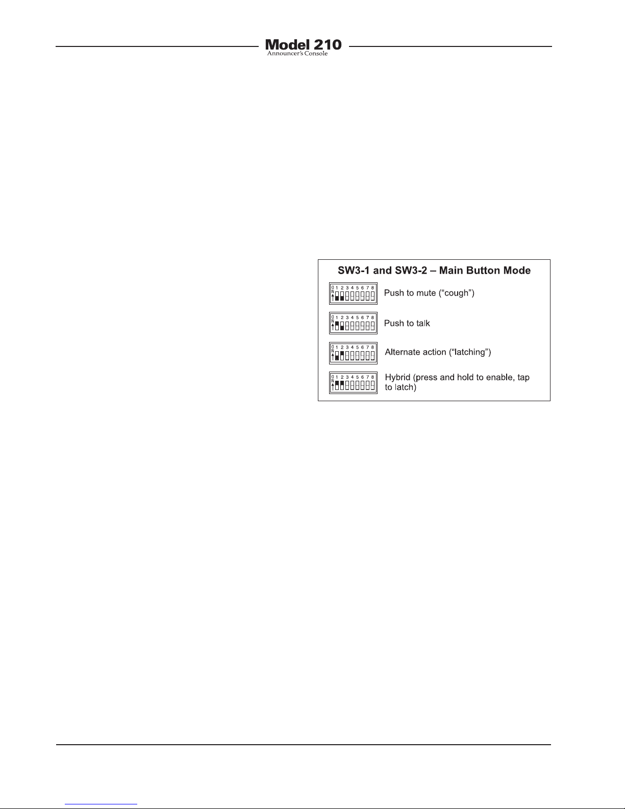
Main Output Button Mode
Switches SW3-1 and SW3-2 configure
how the main output button functions.
Figure 8. Main output button mode settings
There are four available modes:
• Push to mute: In this mode the main
output is normally active. The main out-
put will mute whenever the button
is pressed and held. This is the “cough”
mode typically used for on-air sports
broadcasting applications.
• Push to talk: In this mode the main out-
put is normally muted. The main output
will become active whenever the button
is pressed and held.
• Alternate action: In this mode the main
output will change between its active
and muted state whenever the button
is pressed. Upon power up the main
output will be in its muted state.

Model 210 User Guide Issue 4, October 2008
Studio Technologies, Inc. Page 19
• Hybrid: This mode is a combination
of push to talk and alternate action. It’s
similar to the way talk buttons function
on user stations associated with broad-
cast and production intercom systems.
If the button is pressed and held, the
main output will become active until
the button is released. If the button is
momentarily “tapped” the main output
will change state. Upon power up the
main output will be in its muted state.
Talkback Output Button Mode
Switch SW3-3 configures the way the talk-
back output button functions.
configuration the way the controls func-
tion. With just these three switches a wide
range of operating modes can be con-
figured. Carefully reviewing the capabili-
ties of the available functions may prove
worthwhile.
Dual-Channel or Stereo Mode
Switch SW3-4 is used to select whether
the controls provide a dual-channel (“lev-
el/level”) or stereo (“level/balance”) mode
of operation. In the level/level mode the
two controls operate independently, each
controlling the level of one of the head-
phone output channels. This mode is
generally used for on-air broadcast ap-
plications where independent cue signals
are provided to the left- and right-head-
phone channels. In the level/balance
mode the left rotary control sets the overall
output level for both headphone channels.
The right rotary control is used to adjust
the balance (the relative levels) of the left
and right channels. This mode is generally
best suited for applications where a stereo
cue source is being provided.
Figure 10. Headphone control mode settings
Figure 9. Talkback output button mode settings
Two modes are available:
• Push to talk: In this mode the talkback
output is normally muted. The talkback
output will become active whenever the
button is pressed and held.
• Hybrid: This mode is a combination of
push to talk and alternate action. If the
button is pressed and held, the talk-
back output will become active until
the button is released. If the button
is momentarily “tapped” the talkback
output will change state. Upon power up
the talkback output will be in its muted
state.
Headphone Output Operating Modes
The user is provided with two rotary level
controls (“pots”) that are associated with
the stereo headphone output. Switches
SW3-4, SW3-5, and SW3-6 are used to
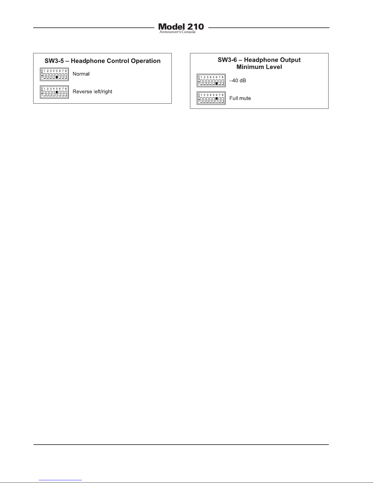
Reverse Left/Right Mode
Switch SW3-5 is used to select whether
the rotary controls are in the normal or
reverse left/right mode of operation. When
selected to the normal mode, and level/
level mode is also selected, the left control
adjusts the level of headphone output’s
left channel. (This is the signal that
appears on the tip lead of the ¼-inch
Issue 4, October 2008 Model 210 User Guide
Page 20 Studio Technologies, Inc.
3-conductor jack.) The right control ad-
justs the level of the right channel. When
selected to the normal mode, and the lev-
el/balance mode is also selected, turning
the balance control in the counterclock-
wise direction increases the perceived
level of the left channel, and vice versa.
As you may have already guessed, when
selecting the reverse left/right mode of op-
eration everything is reversed! To be more
specific, when selected for reverse mode,
and the level/level mode is also selected,
the left control adjusts the headphone
output’s right channel (output jack’s ring
lead) while the right control adjusts the
left channel. When selected to the reverse
mode, and the level/balance is also se-
lected, turning the balance control in the
counterclockwise direction increases the
perceived level of the right channel, and
vice versa.
The reverse mode is provided specifically
for cases where a headset’s left and right
ear pieces are placed on a user’s head in
a reverse orientation. This ensures that
the user is provided with a consistent
and easy-to-use set of headphone level
controls.
Minimum Level Mode
Switch SW3-6 is used to configure the
headphone output’s minimum level. In
the –40 dB mode the minimum head-
phone output level is 40 dB below
maximum. The headphone output chan-
nels will never fully mute. This ensures that
any audio signal present on the selected
Model 210 inputs will always be present
on the headphone output. In most on-air
broadcast applications this is the appropri-
ate setting.
When the full mute mode is selected,
and the level/level mode is also selected,
moving either control to its fully counter-
clockwise position will cause its associ-
ated channel to fully mute.
When the full mute mode is selected, and
the level/balance mode is also selected,
turning the level control to its fully coun-
terclockwise position will cause both
headphone channels to mute. Turning the
balance control to either its fully clock-
wise or fully counterclockwise position will
cause the appropriate channel to mute.
Selecting the full mute mode may be
appropriate for applications where mini-
mizing the chance of audio “leakage”
is important. This could occur when the
connected headset or headphones are at
times placed on a desk or tabletop.
Main Output Source
Switch SW3-7 is used to select which
audio source is routed to the main output.
The choices are the output of the micro-
phone preamplifier or the output of the
compressor circuit. For most on-air
Figure 12. Headphone output minimum level
settings
Figure 11. Headphone control operation
settings
Table of contents


