StudioComm 60 User manual

© 1998 by Studio Technologies, Inc., all rights reserved
5520 West Touhy Avenue
Skokie, Illinois 60077 U.S.A.
Telephone (847) 676-9177
Fax (847) 982-0747
www.studio-tech.com
Model 60 Central Controller and
Model 61 Control Console
User Guide
50076-398, Issue 2
Issue 2, March 1998
This User Guide is applicable for serial numbers:
Model 60 00200 to 00300
Model 61 00151 and later

Model 60/61 User Guide Issue 2, March 1998
Studio Technologies, Inc. Page 3
Table of Contents
Foreword..................................................................... 5
Introduction ................................................................. 7
What This User Guide Covers ................................ 7
System Overview .................................................... 7
System Features..................................................... 7
Installation................................................................... 10
Configuration............................................................... 15
Operation .................................................................... 15
Troubleshooting .......................................................... 18
Technical Notes .......................................................... 18
Specifications .............................................................. 21
Block Diagrams
Model 60 Central Controller
Model 61 Control Console

Model 60/61 User Guide Issue 2, March 1998
Studio Technologies, Inc. Page 5
Foreword
I am pleased to present the StudioComm series of products. As both president and owner
of Studio Technologies, I take a very personal approach when designing products. Getting
older has increased my appreciation of the more subtle things in life—be they a part of
nature or the nuances contained in a well-designed piece of electronic equipment. Do the
technical and operational aspects of a product work together to “feel” right? A Studio Tech-
nologies’ design is ready to go only when I am completely satisfied. My entire focus for the
StudioComm series was to make a system that you’d really enjoy using, and one that
would perform reliably for years. I hope you share my enthusiasm.
Many fine people worked toward making the StudioComm “happen.” Mitch Budniak (ace
consulting engineer) designed many of the circuits. Jim Cunningham contributed to the
analog design. Carrie Loving provided engineering support. Al Lux designed the printed
circuit boards. Fred Roeck performed the mechanical design. Joe Urbanczyk coordinated
the safety testing and agency approvals.
Many thanks to Bob Tjarks, professional audio sales manager at Gand Music & Sound,
Northfield, Illinois. Bob brought to my attention the need for a product to serve digital audio
workstations. His product idea evolved into the StudioComm series. Additional thanks to
Timothy Powell of Metro Mobile Recording, Glenview, Illinois, who provided his excellent
ears when issues of sonic quality arose. His extensive field and studio experience was
extremely helpful in keeping me on the audio “straight and narrow.”
Studio Technologies is receptive to your comments and questions. Please contact me via
phone (847) 676-9177, fax at (847) 982-0747, or the Internet at www.studio-tech.com—I’d
like to hear from you.
Sincerely,
Gordon K. Kapes
President

Model 60/61 User Guide Issue 2, March 1998
Studio Technologies, Inc. Page 7
Introduction
The Model 60 Central Controller, along
with the companion Model 61 Control
Console, are members of the StudioComm
family of products. The Models 60 and 61
are specifically designed to work in con-
junction with digital audio workstations to
provide routing, monitoring, and communi-
cations functions. Features include insert
switching, control room monitoring, dub
(copy) output, and an integrated head-
phone cue system. Several of the func-
tions can be configured, allowing the
performance to be tailored to a specific
installation.
What This User Guide Covers
This User Guide is designed to assist you
when installing and using the Model 60
Central Controller and the Model 61 Con-
trol Console. A limited amount of trouble-
shooting information is also provided.
Should you require detailed technical
information please refer to the Service
Guide covering the Models 60 and 61. The
Service Guide contains detailed service
information, including schematic diagrams.
The Service Guide is not shipped with
each StudioComm system, but is available
from the factory upon request. It is free of
charge to purchasers of StudioComm
equipment. Give us a call or send a fax or
E-mail if you need this highly exciting
document!
System Overview
The StudioComm system is designed to
provide control over monitor and dub
sources, implements a passive insert
switching system, and includes a head-
phone cue system that allows communica-
tions from the control room to the talent. A
complete StudioComm system consists of
a rack-mounted controller and a desktop
control console.
The Model 60 Central Controller and the
Model 61 Control Console work together
to provide a simple, convenient operator
interface, extensive features, and excellent
sonic performance. The units interconnect
using a standard 5-pin MIDI-style cable.
Switches and controls on the Model 60’s
front panel allow access to many operating
parameters, including activating insert
devices, selecting control room and dub
input sources, and setting headphone cue
system level. The Model 61 Control Con-
sole places the most important controls at
the operator’s finger tips. These include
the control room level potentiometer and
monaural button, as well as the cue micro-
phone and enable button.
System Features
Insert Switcher
The insert switcher section allows an
unbalanced stereo audio signal to be
routed to up to three processing devices.
This feature is specifically provided to
allow an analog output signal from an
audio workstation to be processed by
equalizers, compressors, or other analog
devices, then be returned to the work-
station’s analog input. Three switches on
the Model 60’s front panel are used to
select which one (or more) of the three
devices are active in the insert audio
chain.
Alternately, the insert switcher can be
wired so as to create a four input/one
output stereo input source switcher. This
can be used for routing analog sources
to a work station’s analog input.
Issue 2, March 1998 Model 60/61 User Guide
Page 8 Studio Technologies, Inc.
Stereo Line Inputs
The Model 60 contains four stereo line-
level inputs which are compatible with both
balanced and unbalanced signals. Each
input is independently configurable for a
nominal input level of –10dBV or +4dBu.
Analog audio outputs from digital audio
workstations, DAT recorders, video editing
equipment, CD players, cassette decks,
or virtually any analog source can be
connected.
Control Room Output
A stereo line-level output is provided for
connection to a power amplifier associated
with control room monitor loudspeakers.
Switches on the Model 60’s front panel
allow selection of one or more of the four
input signals as the control room source.
A smooth-feeling rotary control on the
Model 61 Control Console allows the
control room level to be adjusted. As a
production or mixing aid, the Model 61
contains a button that activates the control
room monaural (L+R) function.
For broadcast or other special application,
an external switch or contact closure can
be connected to the Model 60, allowing
the control room output to be fully muted
as required. An LED indicator on the
Model 60’s front panel lights whenever
mute is active. A power up/power fail
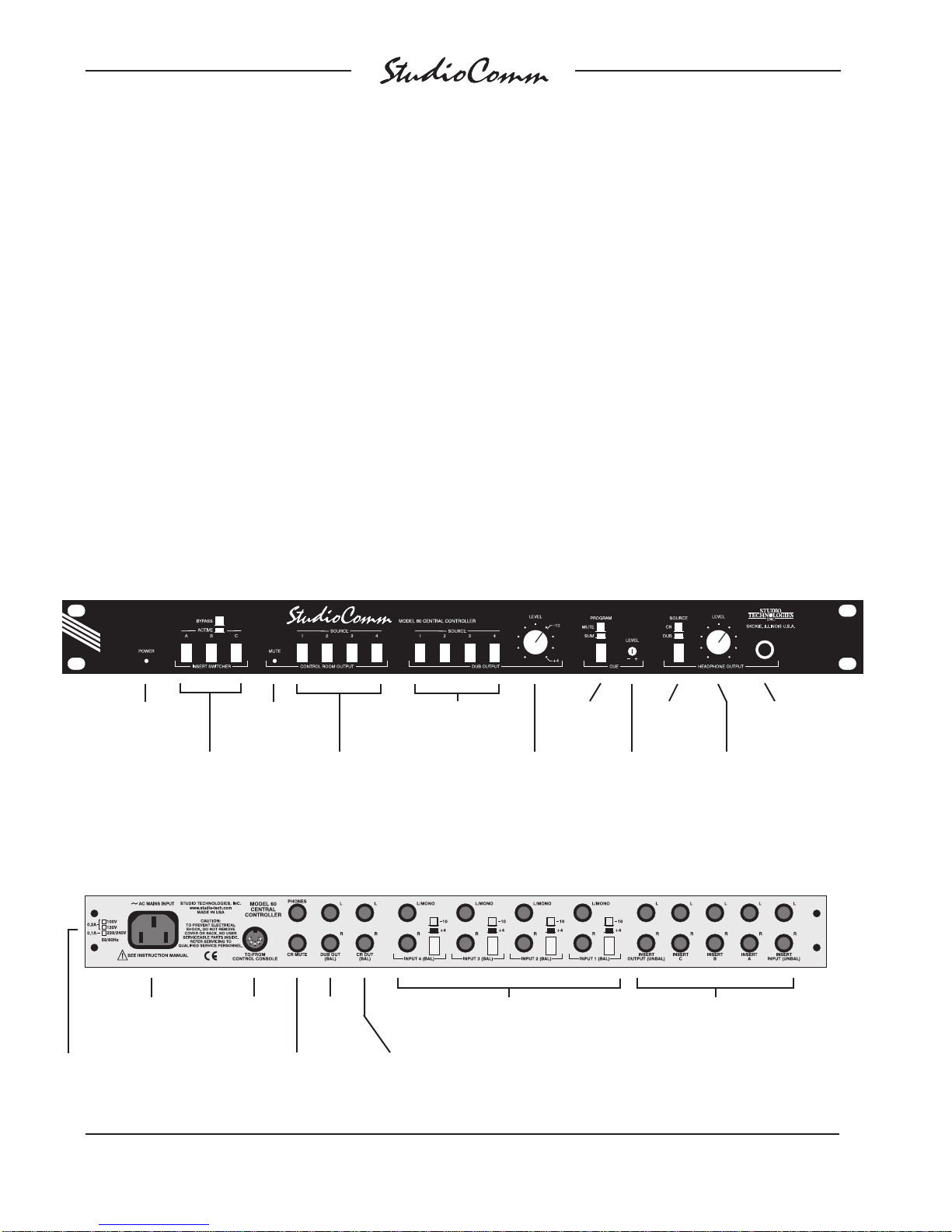
Model 60 Front Panel
Insert switcher
bypass/active
switches
Dub output
level control
Power
present LED Control room
mute LED
Control room
source switches
Dub source
switches
Cue level
control
Headphone
source switch
Cue program
switch
Headphone
output level
control
Headphone
output jack
Model 60 Back Panel
Mains voltage
configuration chart
AC mains
connection To/from
Model 61
Control Console
Headphone
output; control
room mute input
Dub
output
Control
room output
Stereo line-level
inputs Insert switcher input,
output, and insert device
connections
This manual suits for next models
1
Table of contents


