manuals.online logo
Brands
  1. Home
  2. •
  3. Brands
  4. •
  5. Studiomaster
  6. •
  7. Stereo Equalizer
  8. •
  9. Studiomaster SRQ 62 User manual

Studiomaster SRQ 62 User manual

USER GUIDE
Studioking Limited
Unit 1 Youngs Industrial Estate, Stanbridge Road
Leighton Buzzard, Bedfordshire LU7 4QB UK
Tel : +44 (0)1525 217111 Fax : +44 (0)1525 378466
email : enquiries@studiomaster.com
www.studiomaster.com
In Accordance with our progressive product development, Studiomaster / Studioking Limited
reserve the right to change features and specifications without prior notice.
SRQ
SRQ SERIES ENG V1
Series
1
1. INTRODUCTION
Thank you for buying this Studiomaster product. The SRQ range of graphic equalisers
consists of 3 models: SRQ 30, SRQ 62 & SRQ 62L. They are all versatile, high quality
processors designed specifically for live sound and frequency shaping in installations.
READ THE USER GUIDE
Despite the sophisticated design the SRQ range is a very easy to use although to get the
best from your new purchase, we recommend you read this User Guide before getting
down to any serious work.
UNPACKING
Remove your Studiomaster product from its packaging and ensure that along with this
User Guide you have an A.C. power cord / mains lead and a warranty card. Retain the
packing carton in the eventuality that the unit needs to be returned for service or repair,
and please complete and return your warranty card. Returning the completed warranty
card does not diminish your statutory rights in any way.
Safety Instructions
a. Before connecting the A.C. power cord make sure the product is suitable for you local
A.C. supply. The SRQ can be used on A.C. Voltages between 90-240V.
b. Only use the A.C. power cord / mains lead supplied with the product. Replace if it
becomes damaged in any way.
c. Never operate without, or remove the safety ground (earth) from the A.C.
Power cord / mains lead.
d. Do not attempt to remove any screws or panels. There are no user serviceable parts inside.
e. Do not operate the unit next to heat sources such as radiators.
f. The unit should not be operated or stored near rain or moisture.
g. This equipment must not be exposed to dripping or splashing and no objects filled with
liquids should be placed on top of it.
h. Make a note of the serial number for future use.
I. If the product gets damaged, has been dropped or appears to have developed a fault refer
to a qualified Studiomaster service centre.
WARNING
THIS APPARATUS MUST BE EARTHED (GROUNDED)
5. NOTE
7
CH 1
INPUT
PEAK
OVERLOAD
SENSE
HPF CUT
AMPLIFIER
BOOST
AMPLIFIER
25Hz
TO FILTERS
2 - 31 (2 - 15)
BYPASS
R
BYPASS
SWITCH
CH 1
OUTPUT
LEVEL
(off to +6dB)
(12Hz to 285Hz)
R
(The figure is channel 1, channel 2 is the same)
4. Block Diagram
2
2. Front and rear panel control identification
22
33
11
PUSHPUSH
22
33
11
PUSHPUSH
22
33
11
22
33
11
10
12
11 1
2
6
5
9
8
7a
SRQ30 Front panel
SRQ30 Real panel
2
6
5
9
7a
10
12 11 1
22
33
11
PUSHPUSH
22
33
11
22
33
11
PUSHPUSH
22
33
11
265
9
4a
87a
SRQ62 Front panel
SRQ62 Real panel
6
Connections
Input: Balanced 3pin XLR, 3 pole jack & Phoenix screw terminal
Output: Balanced 3pin XLR, 3 pole jack & Phoenix screw terminal
Power requirements: 90-240V ~ 50/60Hz
Power consumption SRQ30 SRQ62 SRQ62L
10W 14W 17W
Fuse ratings:
Fuse 20x5mm 250V (T1.6AL) (T1.6AL) (T1.6AL)
Size Width 482mm (19") 482mm (19") 482mm (19")
Height 44mm (1.75") 88mm (3.5") 133mm (5.25")
Depth 186mm(7.4") 186mm (7.4") 186mm (7.4")
Weight net: 5.5lb 7.7lb 10lb
shipping: 7.7lb 9.9lb 12.1lb
3
1. Power Switch: turns on and off the SRQ graphic equaliser.
2. Filter level control: Each slider controls corresponding the output level of band-pass filter.
(The central concave is ground, which is used for ensuring flat response.)
3. Hi Pass Filter (HPF) switch Channel 1: With the switch in the 'out' position the filter is
bypassed (not in circuit). When engaged, or in the 'in' position, the filter is active.
4. HPF frequency control Channel 1: when the HPF switch is engaged (item 3) the low
frequency response can be adjusted from 12Hz to 285Hz with a 12dB/octave slope.
This can be used to tailor the low frequency response of the sound system or to
reduce stage rumble.
27
3
46 9
5
7
9
4
63
5
8
SRQ62L Front panel
SRQ62L Real panel
22
33
11
PUSHPUSH
22
33
11
PUSHPUSH
22
33
1122
33
11
10
112 11
5
3. Specification
Frequency response: 10-55kHz
Distortion: 0.004%
Signal to noise ratio ref +4dBu: 98dB
EQ: SRQ30 2/3 octave ISO frequencies
SRQ62, SRQ62L 1/3 octave ISO
SRQ30 frequencies: 25, 40, 63, 100, 160, 250, 400, 630, 1k, 1.6k, 2.5k, 4k, 6.3k, 10k, 16k
SRQ62/62L frequencies: 20, 25, 31.5, 40, 50, 63, 80, 100, 125, 160, 200, 250, 315, 400, 500,
630, 800, 1k, 1.25k, 1.6k, 2k, 2.5k, 3.15k, 4k, 5k, 6.3k, 8k, 10k, 12.5k,
16k, 20k
Gain cut/boost: selectable 15dB/6dB
Fader travel: SRQ30 SRQ62 SRQ62L
25mm 25mm 45mm
Input trim range: infinity to +6dB
Hi Pass Filter SRQ62L: 12-285Hz @ 12dB/octave
Hi Pass Filter SRQ62: 40Hz @ 12dB/octave
Maximum input level: +23dBu balanced, +20dBu unbalanced
Maximum output level: +23dBu balanced, +20dBu unbalanced
Input impendence 20k ohms balanced, 10k ohm unbalanced
Output impendence <150 ohms
Metering 11 segment 2 colour bargraph.
Meter calibration -18 to +9dB, clip illuminates @ +18dBu
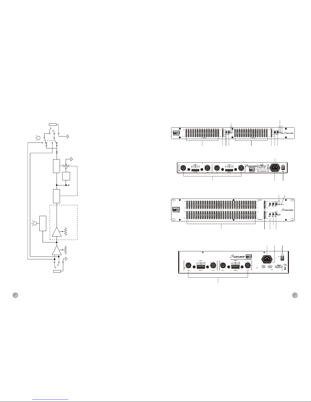
4a. 40Hz high pass filter: when active (switch in) reduces all sounds below 40Hz by 12dB/oct.
5. EQ IN/OUT switch Channel 1: With switch in the 'out' position all the equaliser circuits
are by passed. With the switch engaged, or in the 'in' position, all equaliser circuits are
activated. This allows the operator to compare the equalised and non equaliser sound.
6. Input Trim Control - Channel 1 and Channel 2: adjusts input signal to match the operating
level of the SRQ. The range is from zero (no signal) through unit gain (with centre click) to
+6dB gain.
7. Bargraph level meters. 12 segment LED meter that displays the output level of the SRQ.
7a. Signal and Clip LEDs: indicate when an input signal is present (Sig) and when the input
signal is too high (Clip). Reduce the input level if the Clip LED illuminates to avoid distortion.
8. Power LED: Illuminates when the SRQ is connected to the A.C. supply and the power
switch (item 1) is turned on.
9. Range switch: Selects the cut/boost of the filters between 6dB and 15dB.
10. Output connectors: There are three different output connectors; any combination can
be used in balanced or unbalanced mode.
XLR wiring: Pin 1 = gnd, Pin2 = +ve, Pin = 3-ve
Jack wiring: Tip = +ve, Ring = -ve, Sleeved = gnd
Phoenix connector: wiring marked on rear panel.
11. FUSE: Replace only with same type and rating. Fuse value in Specification section
12. A.C. POWER INLET. Use the cable supplied to connect the SRQ to the A.C. Supply.
4

This manual suits for next models

2

Other Studiomaster Stereo Equalizer manuals

Studiomaster SEQ 312 User manual

Studiomaster

Studiomaster SEQ 312 User manual

Studiomaster SEQ 152 User manual

Studiomaster

Studiomaster SEQ 152 User manual

Popular Stereo Equalizer manuals by other brands

Rockville REQ20 owner's manual

Rockville

Rockville REQ20 owner's manual

Variety Of Sound ThrillseekerXTC manual

Variety Of Sound

Variety Of Sound ThrillseekerXTC manual

DS18 EQX7 owner's manual

DS18

DS18 EQX7 owner's manual

Thermionic Culture Kite operating manual

Thermionic Culture

Thermionic Culture Kite operating manual

Onkyo EQ-35 instruction manual

Onkyo

Onkyo EQ-35 instruction manual

Klark Teknik DN300 Operating and service information

Klark Teknik

Klark Teknik DN300 Operating and service information

Tek'it Audio EQF8 2 user manual

Tek'it Audio

Tek'it Audio EQF8 2 user manual

Lanzar VIBE E740V owner's manual

Lanzar

Lanzar VIBE E740V owner's manual

GA Project EQ-81 quick guide

GA Project

GA Project EQ-81 quick guide

Onkyo EQ-101 instruction manual

Onkyo

Onkyo EQ-101 instruction manual

Biamp EQ 28/8 Operation manual

Biamp

Biamp EQ 28/8 Operation manual

Altec Lansing 1753A SIGNAL PROCESSING Specifications

Altec Lansing

Altec Lansing 1753A SIGNAL PROCESSING Specifications

Sound Performance Lab Classic Vitalizer 9215 manual

Sound Performance Lab

Sound Performance Lab Classic Vitalizer 9215 manual

Rane ME 60 Operator's manual

Rane

Rane ME 60 Operator's manual

Gainlab Audio EMPRESS GL-PEQ manual

Gainlab Audio

Gainlab Audio EMPRESS GL-PEQ manual

BSS Audio FCS 966 user manual

BSS Audio

BSS Audio FCS 966 user manual

Allegion LCN 4810 installation instructions

Allegion

Allegion LCN 4810 installation instructions

Rane GQ 15 Operating and service manual

Rane

Rane GQ 15 Operating and service manual

manuals.online logo
manuals.online logoBrands
  • About & Mission
  • Contact us
  • Privacy Policy
  • Terms and Conditions

Copyright 2025 Manuals.Online. All Rights Reserved.