Sturtevant Richmont Global 400 User manual

Global 400 User Manual
!
v1.1!revision!1!
2 February 2016 Manual Part Number 857412

Global 400 User Manual 2 of 85 v1.1 revision 1
2 February 2016
Table of Contents
Quick Start ...................................................................................................................................... 4!
Chapter 1: Overview ....................................................................................................................... 9!
Warnings ................................................................................................................................... 10!
Cautions .................................................................................................................................... 10!
Unit Overview........................................................................................................................... 11!
Compatible Tools...................................................................................................................... 11!
Chapter 2: Using the unit .............................................................................................................. 12!
Concepts.................................................................................................................................... 13!
Run Screen ................................................................................................................................ 14!
History....................................................................................................................................... 17!
Unit Status................................................................................................................................. 18!
Rundown Graph ........................................................................................................................ 19!
Network Status.......................................................................................................................... 19!
Tool Status ................................................................................................................................ 20!
I/O State .................................................................................................................................... 21!
Chapter 3: Configuring the unit .................................................................................................... 22!
Introduction............................................................................................................................... 23!
Saving Configuration Changes ................................................................................................. 23!
Entering letters .......................................................................................................................... 23!
Main Menu................................................................................................................................ 24!
Tools ......................................................................................................................................... 25!
Parameters................................................................................................................................. 28!
Groups....................................................................................................................................... 33!
Jobs ........................................................................................................................................... 35!
Network Setup .......................................................................................................................... 37!
Unit Setup ................................................................................................................................. 38!
Enter new Password.................................................................................................................. 42!
Reset Defaults ........................................................................................................................... 43!
Channel Change ........................................................................................................................ 44!
Events........................................................................................................................................ 45!

Global 400 User Manual 3 of 85 v1.1 revision 1
2 February 2016
Chapter 4: Serial communications ................................................................................................ 46!
Introduction............................................................................................................................... 47!
Barcode ..................................................................................................................................... 47!
Serial Printer ............................................................................................................................. 50!
Chapter 5: Atlas Copco Open Protocol......................................................................................... 52!
Introduction............................................................................................................................... 53!
Using Groups with Atlas Copco Open Protocol ....................................................................... 53!
Configuration Options .............................................................................................................. 53!
Supported Commands............................................................................................................... 56!
Unsupported Commands........................................................................................................... 57!
Chapter 6: ToolsNet...................................................................................................................... 59!
Introduction............................................................................................................................... 60!
Configuration Options .............................................................................................................. 60!
Chapter 7: EtherNet/IPTM.............................................................................................................. 62!
Vendor-Specific Objects........................................................................................................... 63!
Assembly Object Connection Points ........................................................................................ 71!
Backwards Compatibility Assembly Object Connection Points .............................................. 74!
Chapter 8: Data Management ....................................................................................................... 79!
Download data to USB ............................................................................................................. 80!
Upload USB file to device ........................................................................................................ 81!
Chapter 9: Firmware Updates ....................................................................................................... 82!
Chapter 10: Product Specifications............................................................................................... 84!
Dimensions ............................................................................................................................... 85!
Radio Information..................................................................................................................... 85!

Global 400 User Manual 4 of 85 v1.1 revision 1
Quick Start 2 February 2016
Quick Start

Global 400 User Manual 5 of 85 v1.1 revision 1
Quick Start 2 February 2016
This quick start will guide you through the process of configuring the unit for first time use.
Plug the provided power cable into the unit and 100-240
VAC power and turn on the power switch. The beeper
should sound a series of quick beeps and the display should
show the loading progress.
Once the loading is completed, the unit should go to the
Run screen. If the unit stays on the loading screen with an
error, please contact support.
To use a tool with the Global 400, you must first “learn” the
tool to the Global 400. To do so, press the button below
MENU.
Enter the password (0104 by default) using the numeric
keypad and pressing ENT when completed.
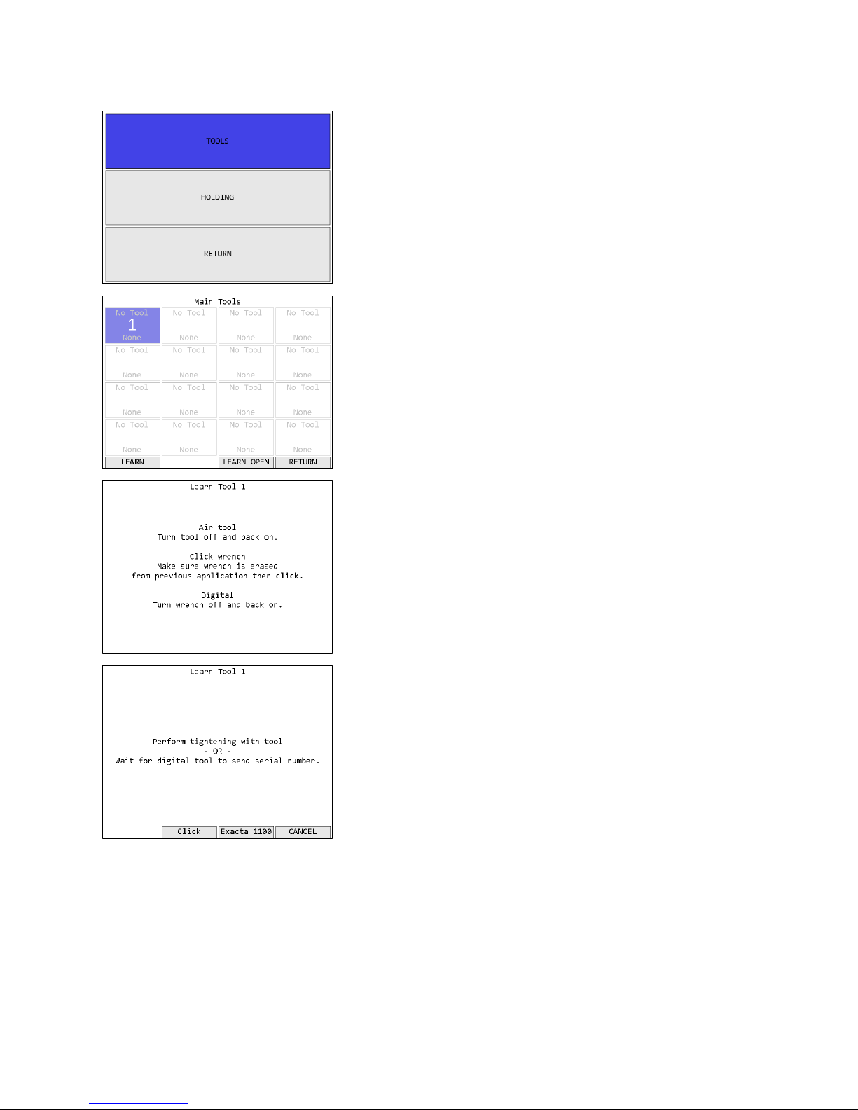
In the menu, press the right arrow to select TOOLS and
press ENT.
Global 400 User Manual 6 of 85 v1.1 revision 1
Quick Start 2 February 2016
In the tools menu, press ENT to go to the main tools page.
If the tool you are going to learn to the Global 400 has
previously been used with another unit, make sure the tool
has been “forgotten” from that unit before continuing. Press
the button beneath LEARN to begin the learn process.
Follow the directions on screen to learn the tool.
Once the tool has found the unit, you may need to perform
an additional step for the unit to know which type of tool
was just learned. Holding tools, air tools, and newer click
tools can be distinguished by the unit, but digital tools and
older click tools will be require some additional
information. The digital tools will automatically transmit
their serial number in a few seconds. However, if you are
learning an older click tool, you will need to perform a
tightening (good or bad) with the wrench, or push the
appropriate button on screen.
Global 400 User Manual 7 of 85 v1.1 revision 1
Quick Start 2 February 2016
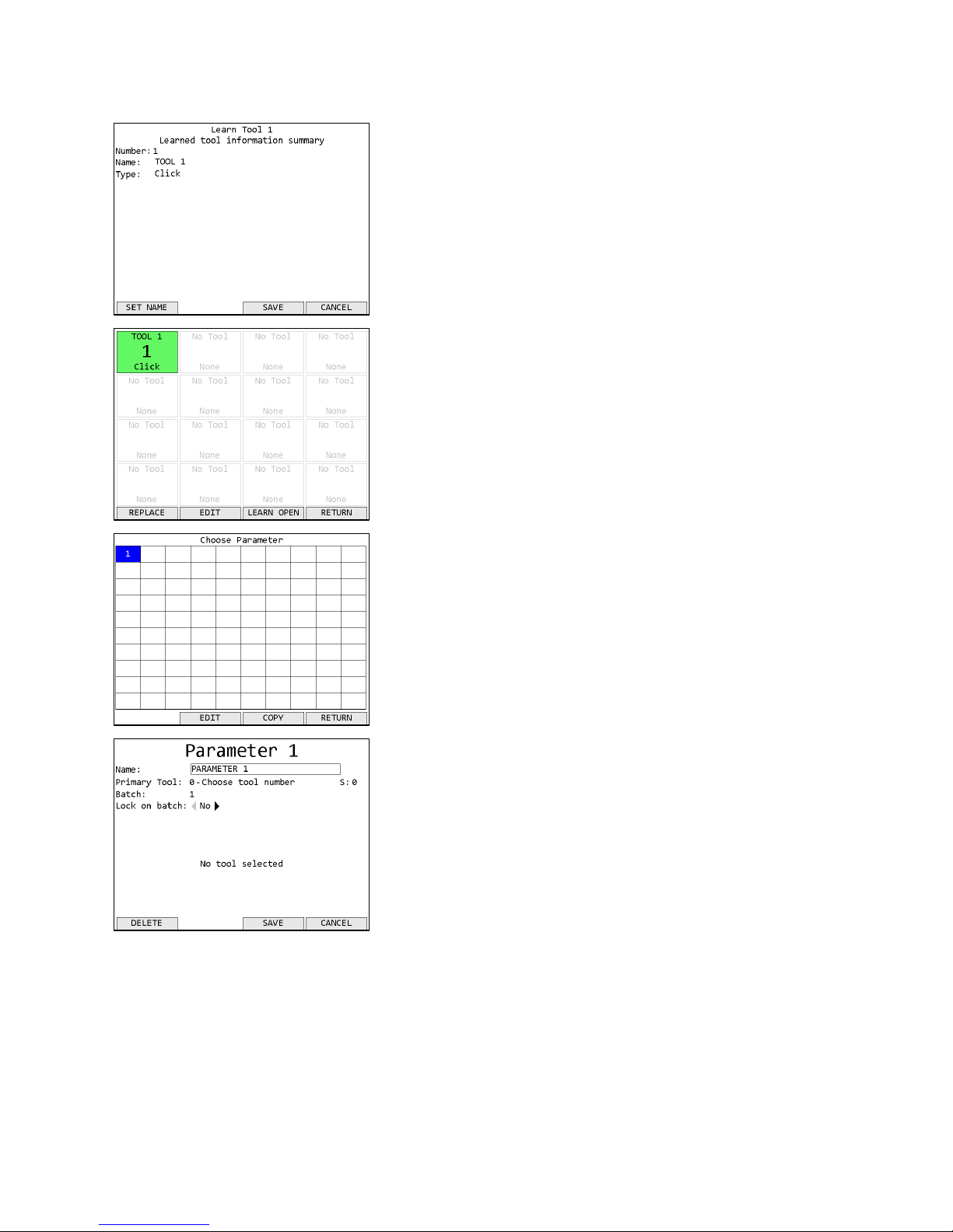
Once the tool learn is completed, the unit will show a
summary of the new tool information. Press SAVE to store
the tool information and continue.
The unit will return to the Tools screen with the just learned
tool now with a tool name of “TOOL 1” instead of “No
Tool”. If the just learned tool is a digital tool, the default
name will be the tool serial number.
Before you can run the tool, you must first assign it to a
parameter. Return to the menu by pressing ESC twice.
Then press ENT to go to the Choose Parameter screen.
Press the button below EDIT to go to the Parameter Edit
screen.
Press the down arrow to move the cursor to the Primary
Tool row, followed by 1 to assign the tool to the parameter.
Press ENT or the button below SAVE to save the changes
and return to the Choose Parameter screen.

Global 400 User Manual 8 of 85 v1.1 revision 1
Quick Start 2 February 2016
Parameter 1 should now be shown in black instead of white
to indicate that it was set up successfully. Press the button
below SELECT to select Parameter 1.
You will be returned to the Run screen, now with Parameter
1 selected. You can now perform tightenings with Tool 1
that will be monitored, stored, and reported by the qualifier.

Global 400 User Manual 9 of 85 v1.1 revision 1
Chapter 1: Overview 2 February 2016Chapter 1: Overview 2 February 2016
Chapter 1: Overview

Global 400 User Manual 10 of 85 v1.1 revision 1
Chapter 1: Overview 2 February 2016
Warnings
Do not disassemble the unit for repair or modifications. There is a high
electrical voltage inside the unit that could cause electric shock.
Do not allow any type of liquid to come into contact with any part of the
unit.
Insert all fittings fully into their mating receptacles. Failure to do so could
result in injury.
Do not fold, bend or apply excessive force to any cable or fitting.
Cautions
Please use caution when handling this or any other electrical appliance.
•This unit accepts an AC input voltage from 100-240 VAC. Trying to operate this unit with a
voltage outside that range may cause damage to the unit.
•Avoid placing or storing this unit in a location where it may become wet or dust covered.
•Do not place or mount this unit in an unstable area.
•Dropping this unit may result in personal injury or damage to the unit.
•Before performing any maintenance on the unit, make sure to turn it off and remove the
power plugs.
•There are no user serviceable parts inside the main enclosure of the unit.
Global 400 User Manual 11 of 85 v1.1 revision 1
Chapter 1: Overview 2 February 2016
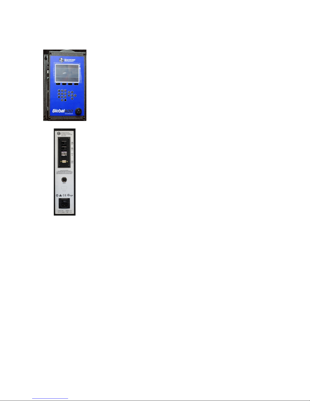
Unit Overview
The Global 400 is equipped with a color LCD display, four function
keys immediately below the LCD, a numeric keypad with decimal
point, navigation keys, and enter and escape buttons. The current
function of the function keys is indicated at the bottom of the LCD
above the button.
The beeper provides an audio indication for any combination of
accepts, rejects, and batch completions. The beeper volume can be
adjusted through the user interface. (See the Unit Setup section in the
next chapter.)
The Global 400 has two RJ-45 Ethernet ports to allow it to be used in a
chain or ring network configuration.
The USB-A connector is used to provide firmware updates via a
standard USB drive.
The RS232 DSUB9 connector can be used with a serial barcode reader
or serial printer.
The 5-pin remote connector connects to other devices that provide I/O
capabilities.
The power plug accepts 100-240 VAC at 50-60 Hz.
Compatible Tools
The Global 400 works with the following models of tools:
•SLTC-FM 2.4 GHz preset clicker-type torque wrenches
•1100-Series Exacta 2 digital torque wrenches
•PST series air tool transducers
•Holding wrenches

Global 400 User Manual 12 of 85 v1.1 revision 1
Chapter 2: Using the unit 2 February 2016
Chapter 2: Using the unit

Global 400 User Manual 13 of 85 v1.1 revision 1
Chapter 2: Using the unit 2 February 2016
Concepts
Tools
The Global 400 can associate with up to 16 Sturtevant Richmont radio torque tools and 8 holding
tools. At most, 4 torque tools and 4 holding tools will be active at a time, depending on the
selected operation. To use a tool with the Global 400, you must first “learn” the tool to the
qualifier. The process to do this is described in the Quick Start.
Tools are not activated directly by the unit. Instead, they are activated when a parameter that
uses the tool is running. A tool may be used by more than one parameter.
The Global 400 can store some information about when calibration or preventative maintenance
should occur. These are set up in the Tool Configuration screen, which is described in the next
chapter.
Parameters
Parameters are the basic unit of operation for the Global 400. A parameter contains a tool to run
and some settings to use with it, such as the batch size and minimum and maximum torques. The
Global 400 supports 100 parameters. Each parameter must be associated with one of the learned
tools before it can be run.
A parameter may additionally have a holding tool assigned.
Groups
Groups are multiple parameters that must all run together and can run simultaneously in any
order. The Global 400 supports 100 groups with up to 4 parameters each. A group cannot
contain more than one parameter that uses a given tool, as it would not be able to determine
which parameter a result should be assigned to. Additionally, a group may only contain
parameters with the same type of primary tools. When defining a group, you may override the
batch count for parameters in the group while the group is running. This does not change the
batch size defined in the parameter. When running a group, all parameters must complete a full
batch before any parameter can begin running a second batch.
Jobs
Jobs are the top level of operation in the Global 400, made up of multiple parameters or groups
that must all run together in a sequence. The Global 400 supports 100 jobs with up to 30 steps
each. Unlike groups, a job may have multiple parameters that use the same tool or even the same
parameter or group multiple times and may use parameters with different types of primary tools.
As with groups, you may override the batch count for parameter steps in the job. You cannot
change the batch sizes for groups when run in a job.

Global 400 User Manual 14 of 85 v1.1 revision 1
Chapter 2: Using the unit 2 February 2016
Run Screen
The run screen shows which parameters the unit is currently running. Depending on the number
of active parameters, the run screen will be in one of several modes.
Figure 1: No active parameter
Figure 2: Suspended
Figure 3: 1 active parameter
Figure 4: 2-4 active parameters
Tightening Notifications
Every time a tightening is received from a running tool, the background of the area of the screen
showing the current parameter and batch count for the tool will be shaded with a color indicating
the status of the tightening.
•Red – A rejected tightening occurred.
•Green – An accepted tightening occurred that did not complete a batch.
•Blue – An accepted tightening occurred that completed a batch. If the qualifier NOKs setting
is set to Count, this further indicates that no rejected tightenings were counted towards this
batch.
•Yellow – An accepted or rejected tightening occurred that completed a batch. This color will
only occur when the qualifier NOKs setting is set to Count and one or more rejected
tightenings were counted towards the current batch.
Global 400 User Manual 15 of 85 v1.1 revision 1
Chapter 2: Using the unit 2 February 2016
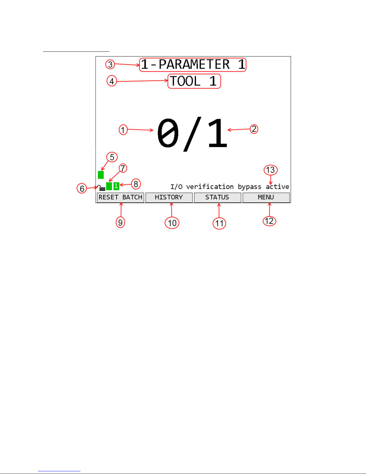
1 Active Parameter
1. Count – The number of tightenings completed in the current batch
2. Batch – The number of tightenings required for the current batch
3. Parameter Name – Name of the currently running parameter. When running a job, this is the
job name and the parameter name is shown below the tool name.
4. Tool Name – Name of the tool for the currently running parameter
5. Tool Status Indicator – Shows the status of the tool for the parameter
6. Unit lock – Indicates if the unit is locked and requires a password to access menu functions
7. Unit Radio Status – Shows the status of the unit radio
8. Network Status – Shows the status of the Ethernet and current number of connections.
9. Function key 1 – Shows the current function of function key 1.
10. Function key 2 – Shows the current function of function key 2.
11. Function key 3 – Shows the current function of function key 3.
12. Function key 4 – Shows the current function of function key 4.
13. Notifications – Shows notifications of unit status beyond radio and network statuses

Global 400 User Manual 16 of 85 v1.1 revision 1
Chapter 2: Using the unit 2 February 2016
2-4 Active Parameters
1. Count – The number of tightenings completed in the current batch of the parameter.
Repeated for each active parameter.
2. Batch – The number of tightenings required for the current batch of the parameter. Repeated
for each active parameter.
3. Group Name – Name of the currently running group.
4. Parameter Name – Name of the parameter. Repeated for each active parameter.
5. Tool Name – Name of the tool for the parameter. Repeated for each active parameter
6. Tool Status Indicator – Shows the status of the tool for the parameter. Repeated for each
parameter
7. Unit lock – Indicates if the unit is locked and requires a password to access menu functions
8. Unit Radio Status – Shows the status of the unit radio
9. Network Status – Shows the status of the Ethernet and current number of connections.
10. Function key 1 – Shows the current function of function key 1.
11. Function key 2 – Shows the current function of function key 2.
12. Function key 3 – Shows the current function of function key 3.
13. Function key 4 – Shows the current function of function key 4.
14. Inactive parameter – When not all the parameter slots on a screen are needed to show all the
active parameters, the rest of the slots will be grayed out.
Tool Radio Status Codes
The radio status indicator for each active parameter shows the status of the tool radio for the
parameter. When the tool is ready to run, the indicator should be green with no number. If the
tool is not ready to run or a warning or error condition occurs, the indicator will change to yellow
for a warning or red for an error and display a code to indicate the radio condition. The possible
codes are:

Global 400 User Manual 17 of 85 v1.1 revision 1
Chapter 2: Using the unit 2 February 2016
Code
Color
Meaning
1
Red
Tool has not communicated with the unit since power-up
2
Yellow
Enabling or disabling tool
2
Red
Tool programming failed
3
Yellow
Tool is disabled
4
Yellow
The battery is low. It should be changed when possible to avoid interruptions in service.
Only click and holding tools provide battery level information.
4
Red
The battery is very low. Interruptions in service may occur until the battery is replaced.
5
Yellow
Radio signal strength is below recommended level for best performance
5
Red
Radio signal strength is below recommended minimum level for use
6
Yellow
Tool requires calibration
7
Yellow
Tool requires preventative maintenance
Unit Radio Status Indicator
The unit radio status indicator shows the status of the radio in the unit. In normal use, the
indicator should be green with no number. If the radio is not working correctly, the indicator
will be red with an error code.
Network Status Indicator
The network status indicator shows the status of the Ethernet ports on the unit. When the
Ethernet is used, the indicator will be green and show the number of currently active network
connections. If no Ethernet cable is plugged into either port, the indicator will be yellow. If the
network initialization fails, the indicator will be red and show an error code. The Network Status
screen shows more detailed information.
History
Figure 5: History screen
Function keys
1. No function
2. PREVIOUS – Go to the previous page of more recent tightenings. When on the first page,
this key will be blank.
3. NEXT [ENT] – Go to the next page of older tightenings. When on the last page, this key
will be blank.
4. RETURN [ESC] – Returns to the Run Screen.

Global 400 User Manual 18 of 85 v1.1 revision 1
Chapter 2: Using the unit 2 February 2016
The History screen shows some information about the tightenings stored in unit memory. More
information about the tightenings is not shown but is available via the network protocols. This
screen shows
•Time – The time the tightening occurred. The date is indicated at the top of the table and
each time it changes in a white row.
•T# – The tool number that produced the tightening
•Param – The number and name of the parameter that produced the tightening
•Count – The current batch count and batch size for the tightening
•Torque – The torque of the tightening. This value is only provided for digital tools. The unit
of torque will be whatever the unit of the parameter that produced the tightening was at the
time.
•Id – The tightening id number. This screen shows only the last 4 digits of the id number;
additional digits may be present in the network commands.
Unit Status
Figure 6: Unit Status screen
Function keys
1. GRAPH – When a single air tool is running, goes to the Rundown Graph screen. For other
tool types or when a group is running, this key has no function.
2. NETWORK – Go to the Network Status screen.
3. TOOL – Go to the Tool Status screen.
4. I/O – Go to the I/O State screen
The Unit Status screen shows some basic information about the current unit configuration that
may be useful for diagnostics purposes. Press ESC to return to the Run Screen
The average signal strength is for all tools learned to the unit and should be from 0 to -70 dBm.
If the signal strength is weaker, the unit may have frequent slow or failed communication. To
improve the signal strength, try bringing the unit and tools closer together, changing the XBEE
channel, or reducing sources of interference from the environment.
Last barcode shows the command number of the last barcode scanned (see Chapter 4: Serial
communications) or an error if the last attempt barcode could not be processed. VIN and ID 2-4
show what will be included with tightenings in the associated result data fields.

Global 400 User Manual 19 of 85 v1.1 revision 1
Chapter 2: Using the unit 2 February 2016
Rundown Graph
Figure 7: Rundown Graph screen
Function keys
1. EDIT – Go to the Parameter Edit screen for the running parameter. This will require the
password to be entered.
2. No function
3. REFRESH – Refresh the graph with the data for the most recent run of the tool.
4. RETURN [ESC] – Returns to the Unit Status Screen.
The Rundown Graph screen retrieves and shows the last rundown from an air tool. The rundown
will be overlaid with yellow horizontal lines for each of the three thresholds and vertical lines
showing the timers, purple for Timer Min and Timer Max, blue for Timer Clutch. Additionally,
the total time for the rundown is shown at the right end of the horizontal axis.
Network Status
Figure 8: Network Status screen
The network status screen shows the current Ethernet status
of the unit. The MAC address is assigned by the factory
and cannot be changed. The IP address, subnet mask, and
gateway may be edited from the Network Setup - General
screen or assigned via DHCP.
The Ethernet 1 and 2 lines indicate if a physical cable
connection is detected on the corresponding Ethernet ports
of the unit. If no connection on a port is detected, the unit
will show “Not connected”. If a connection is detected, the
baud rate and duplex of the connection will be listed.
Global 400 User Manual 20 of 85 v1.1 revision 1
Chapter 2: Using the unit 2 February 2016
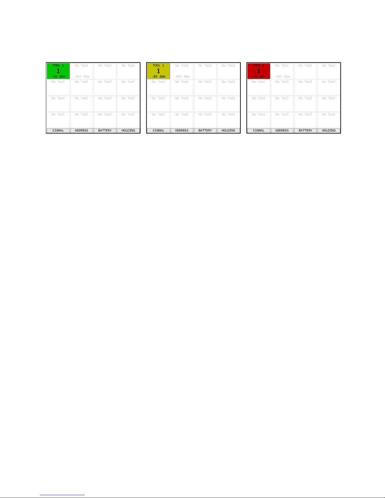
Tool Status
Figure 9: Tool Status - Good Signal
Figure 10: Tool Status – Low Signal
Figure 11: Tool Status - Bad Signal
Function keys
1. SIGNAL – Show the signal strength of each tool.
2. ADDRESS – Show the address of each tool
3. BATTERY – Shows the battery level of each tool, if available. Not all tools report battery
level.
4. HOLDING / TOOLS – Toggles between showing main tools and holding tools.
The Tool Status screen shows the status of the tools learned into the unit. This screen shows the
signal strength of the last packet from the tool but can also show the radio address and battery
level of the tools. Press ESC to return to the Unit Status screen.
For signal strength, a less negative number indicates a better signal (-50 dBm is better than -60
dBM). The screen shows a color based on the quality of the signal.
•Green – The signal from this radio is strong and will work at best performance.
•Yellow – The signal from the radio is weaker than recommended for best performance. The
radio should work but may have slower or occasionally interrupted communication with the
unit.
•Red – The signal from the radio is weaker than recommended for any use. The radio may
successfully transmit some results but will frequently have slow or failed communication
with the unit. If only one tool is red, bring it and unit closer together. If multiple tools are
red, consider using a different radio channel (changed from the Unit Setup screen).
For battery level, the charge remaining is shown. Not all tools report their current battery level.
The screen shows a color based on the level.
•Green – The battery is full and will work at best performance.
•Yellow – The battery is low and should be changed when possible.
•Red – The battery is very low and should be changed. The tool may fail to transmit some
results until the battery is changed.
Table of contents
Other Sturtevant Richmont Measuring Instrument manuals

Popular Measuring Instrument manuals by other brands

TSI Incorporated
TSI Incorporated VELOCICALC 5725 Operation and service manual

Agilent Technologies
Agilent Technologies 35670A quick start guide

Dillenger
Dillenger KT-LCD3 user manual

Pfeiffer Vacuum
Pfeiffer Vacuum IKR 251 operating instructions

LaserLiner
LaserLiner MeterMaster Plus quick start guide

Muller Ziegler
Muller Ziegler DSMG 96 manual


