Sub-Zero Wolf Drop-Down Door Series User manual

Page 2
Microwave Drop-Down Door Series
General Information
1-2
#826151 - Revision A - March, 2016
INTRODUCTION
This Technical Service Manual has been compiled to provide the most recent technical service information. This
information enables the service technician to troubleshoot and diagnose malfunctions, perform necessary repairs
and return the appliance to proper operational condition.
The service technician should read the complete instructions contained in this service manual before initiating any
repairs on a Wolf Appliance.
For installation information see Drop-Down Door Microwave Oven Installation Guide available at http://www.sub-
zero-wolf.com/trade-resources/product-specifications.
For Use and Care information see Drop-Down Door Microwave Oven Use and Care Guide available at
http://www.subzero-wolf.com/trade-resources/product-specifications.
This manual is designed to be used by Certified Service Personnel only. Wolf Appliance, Inc. assumes no
responsibility for any repairs made to Wolf appliances by anyone other than Certified Service Technicians.
The information and images are the copyright property of Wolf Appliance, Inc., an affiliate of
Sub-Zero Group, Inc. Neither this manual nor any information or images contained herein may be copied or used in
whole or in part without the express written permission of Wolf Appliance, Inc., an affiliate of Sub-Zero Group, Inc. ©
Wolf Appliance, Inc., all rights reserved.
Microwave Radiation
Personnel should not be exposed to the microwave energy which may radiate from the magnetron or other
microwave generating devices if it is improperly used or connected. All input and output microwave connections,
waveguides, flanges and gaskets must be secured. Never operate the device without a microwave energy absorb-
ing load attached. Never look into an open waveguide or antenna while the device is energized.
Never operate the oven until the following points are ensured.
The door is tightly closed.•
The door and oven hinges are not defective.•
The door packing is not damaged.•
The door is not deformed or warped.•
There is not any other visible damage with the oven.•

Page 3
General Information
Microwave Drop-Down Door Series
1-3 #826151 - Revision A - March, 2016
•
Distinct styles to compliment the look of Wolf “E” and•
“M” series ovens.
Bottom hinged door.•
Large-capacity interior.•
Sensor cooking to monitor and adjust settings.•
Warming feature for gentle heating.•
Reheat feature is perfect for leftovers.•
24” and 30” widths.•
Standard or flush inset application.•
MICROWAVE FEATURES
MICROWAVE RATING PLATES
MODEL MDD30CM/B/TH
HOUSEHOLD MICROWAVE OVEN
NOT FOR COMMERCIAL USE Manufactured: December 2015
120V AC 60Hz 13.5A
Made in Thailand
COMPLIES WITH DHHS RADIATION PERFORMANCE STANDARDS 21 CFR SUBCHAPTER J
Serial No. 12345678
FCC ID: APYDMRO178
Figure 1-1. Rating Plate
WOLF APPLIANCE, INC.
2866 BUD’S DRIVE, FITCHBURG, WI 53719 USA.
MDD30CM/B/TH
MDD30TM/S/TH 9004648
Bar Code
Figure 1-2. Supplemental Label
RATING PLATE LOCATION
Figure 1-3. Label Locations
Rating Label
Supplemental Label

Page 4
Microwave Drop-Down Door Series
General Information
1-4
#826151 - Revision A - March, 2016
MICROWAVE MEASUREMENT
After adjustment or replacement of the door latch switches, monitor switch, or the door is completed individually or
collectively, the following leakage test must be performed. The survey instrument and the result must meet the
requirements of the performance standard for microwave ovens.
REQUIREMENT
The safety switch must prevent microwave radiation emission in excess of 5mW/cm2 at any point 5 cm (2 inches) or
more from the external surface of the microwave oven.
PREPARATION FOR TESTING (from Code of Federal Regulation Title 21)
Before beginning the actual test for leakage, proceed as follows;1
Make sure that the test instrument is operating normally as specified in its instruction booklet.2
Important: Survey instruments that comply with the requirement for instrumentations as prescribed by the
performance standard for microwave ovens must be used for testing.
Place the oven tray into the oven cavity.3
Place the load of 275 ± 15 ml of water initially at 20 ± 5°C in the center of the oven tray. The water container4
should be a low form of 600 ml beaker with inside diameter of approx. 8.5 cm and made of an electrically non-
conductive material such as glass or plastic. The placing of this standard load in the oven is important not only
to protect the oven, but also to insure that any leakage is measured accurately.
Close the door and turn the oven ON with the timer set for several minutes. If the water begins to boil before the5
survey is completed, replace it with 275 ml of cool water.
Move the probe slowly (not faster that 2.5 cm/sec.) along the gap.6
The microwave radiation emission should be measured at any point of 5 cm or more from the external surface of7
the oven.
Figure 1-4. Microwave leakage testing

Page 5
General Information
Microwave Drop-Down Door Series
1-5 #826151 - Revision A - March, 2016
Refer to this key for an example of the model numbers.
Model: ICB MDD 30 PM / S / PH
International Designation
Product
Size
Model
Unit Style
Handle Style
Product
MDD = Microwave Drop-Down Door
Size
24 = 24 - inch wide unit
30 = 30 - inch wide unit
Model
TE = Transitional “E” Series
TM = Transitional “M” Series
CM= Contemporary “M” Series
PE = Professional “E” Series
PM = Professional “M” Series
Unit Style
S= Stainless Steel
B= Black Glass
Handle Style
TH = Tubular Handle
PH = Professional Handle
MODEL NUMBER KEY

Page 6
Microwave Drop-Down Door Series
General Information
1-6
#826151 - Revision A - March, 2016
Description: Microwave Drop-Down Door, 24”,
Transitional “E” Series, Stainless Steel, Professional
Handle
MDD24TE/S/PH MDD30CM/B/TH
Description: Microwave Drop-Down Door, 30”,
Contemporary “M” Series, Black Glass, Tubular Handle
24” Transitional 30” Contemporary

Page 7
General Information
Microwave Drop-Down Door Series
1-7 #826151 - Revision A - March, 2016
MDD30PM/S/PH
MDD30PE/S/PH
Description: Microwave Drop-Down Door, 30”,
Professional “E” Series, Stainless Steel, Professional
Handle
Description: Microwave Drop-Down Door, 30”,
Professional “M” Series, Stainless Steel, Professional
Handle
MDD30TM/S/TH
MDD30TE/S/TH
Description: Microwave Drop-Down Door, 30”,
Transitional “M” Series, Stainless Steel, Tubular Handle
Description: Microwave Drop-Down Door, 30”,
Transitional “E” Series, Stainless Steel, Tubular Handle
30” Transitional30” Professional

Page 8
TIMER CLOCK
The clock must be set prior to use and after a power outage.
Setting the clock:
Touch STOP/CLEAR1.
Touch TIMER/CLOCK once for 12-hour mode or twice for 24-hour mode2.
Use the number pads to enter the time of day3.
Touch START4.
The timer can be set for a maximum of 99 minutes and 99 seconds. Once a time is set, the countdown appears
on the control panel display. The microwave chimes and END appears on the display when complete.
Setting the timer:
Touch TIMER/CLOCK1.
Use the number pads to enter timer duration2.
Touch START to begin3.
Touch STOP/CLEAR to cancel4.
SETTINGS
The settings feature allows the user to select individual preferences. Preference must be reset after a power out-
age.
AUDIBLE SIGNAL
An audible signal chimes with every touch and upon cook time and timer completion.
To eliminate signal:
Touch SETTINGS - control panel display scrolls “TOUCH DECREASE FOR SOUND OFF”1.
Touch DECREASE - control panel display scrolls “SOUND OFF - TOUCH START”2.
Touch START3.
“SOUND OFF” appears on the control panel display, then the time of day4.
To restore signal:
Touch SETTINGS - control panel display scrolls “TOUCH INCREASE FOR SOUND ON”1.
Touch INCREASE - control panel display scrolls “SOUND ON - TOUCH START”2.
Touch START3.
“SOUND ON” appears on the control panel display, then the time of day4.
Microwave Drop-Down Door Series
Controls & Operation
2-2
#826151 - Revision A - March, 2016
CONTROLS
This section describes the basic operation of the Drop-Down Door Microwave and how the touch panel assembly
responds to input commands.
Panel Assembly

Page 9
Controls & Operation
Microwave Drop-Down Door Series
2-3 #826151 - Revision A - March, 2016
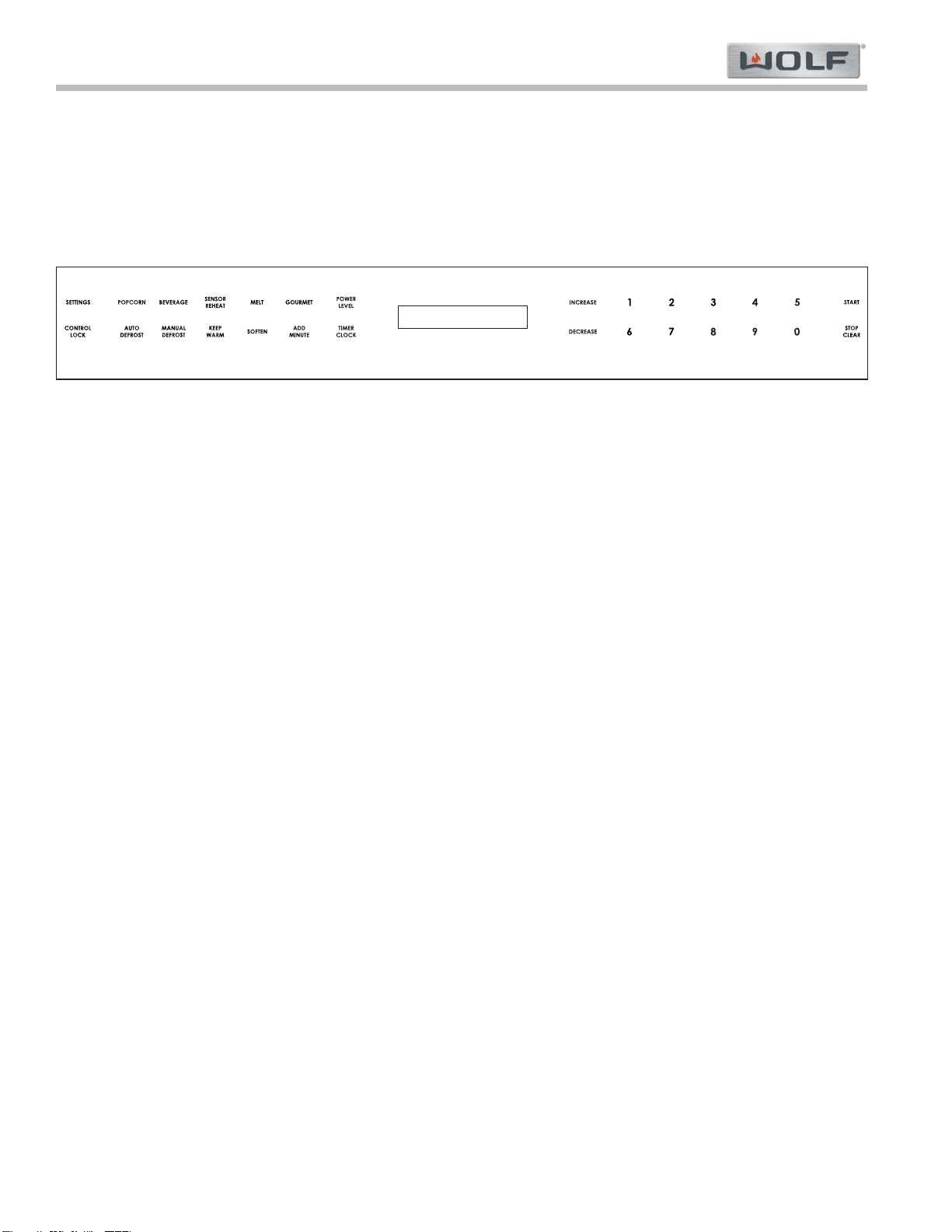
COOK TIME COMPLETION REMINDER
Upon completion, the microwave oven chimes every ten seconds for the first minute; then every three minutes
(for one hour) until STOP/CLEAR is touched.
To eliminate reminder:
Touch SETTINGS twice - control panel display scrolls “REMIND SIGNAL ON TO TURN REMIND SIGNAL OFF1.
TOUCH DECREASE”
Touch DECREASE - control panel display scrolls “REMIND SIGNAL OFF TOUCH START”2.
Touch START3.
“REMIND SIGNAL OFF” appears on the control panel display, then the time of day4.
To restore reminder:
Touch SETTINGS twice - control panel display scrolls “REMIND SIGNAL OFF TO TURN REMIND SIGNAL ON1.
TOUCH INCREASE”
Touch INCREASE - control panel display scrolls “REMIND SIGNAL ON TOUCH START”2.
Touch START3.
“REMIND SIGNAL ON” appears on the control panel display, then the time of day4.
WEIGHT UNIT
For cooking modes where weight is required, the default unit of measure can be change from pounds to kilo-
grams.
To change unit of measure to kilograms:
Touch SETTINGS three times - display scrolls “CHANGE WEIGHT TO KGS? TOUCH DECREASE”1.
Touch DECREASE - control panel display scrolls “WEIGHT KGS TOUCH START”2.
Touch START3.
“KGS SET” appears on the control panel display, then the time of day4.
To change unit of measure to pounds:
Touch SETTINGS three times - display scrolls “CHANGE WEIGHT TO LBS? TOUCH INCREASE”1.
Touch INCREASE - control panel display scrolls “WEIGHT LBS TOUCH START”2.
Touch START3.
“LBS SET” appears on the control panel display, then the time of day4.
FACTORY SETTINGS
To restore the microwave oven to factory settings:
Touch SETTINGS four times - display scrolls “TOUCH START TO RESTORE FACTORY SETTINGS”1.
Touch START2.
“FACTORY SETTINGS RESTORED” appears on the control panel display, then the time of day.3.
DEMONSTRATION MODE
Demonstration mode allows operation to be demonstrated without powering the magnetron.
To enter demonstration mode:
Touch SETTINGS five times - display scrolls “DEMO ON? TOUCH INCREASE”1.
Touch INCREASE - display scrolls “TOUCH START”2.
Touch START3.
“DEMO ON” appears on the control panel display, then “DEMO” remains on the display4.
To exit demonstration mode:
Touch SETTINGS five times - display scrolls “DEMO OFF? TOUCH DECREASE”1.
Touch DECREASE - display scrolls “TOUCH START”2.
Touch START3.
“DEMO OFF” appears on the control panel display, then the time of day4.

Page 10
Microwave Drop-Down Door Series
Controls & Operation
2-4
#826151 - Revision A - March, 2016
CONTROL LOCK
The control lock feature prevents unwanted microwave oven operation.
To lock:
Touch CONTROL LOCK1.
Touch START2.
LOCK ON appears on the control panel display3.
To unlock:
Touch CONTROL LOCK1.
Touch START2.
LOCK OFF appears on the control panel display3.
POPCORN
The popcorn feature has two options. Follow directions on the control panel display to select the desired option.
Use only popcorn packaged for microwave ovens.
To use popcorn:
Touch POPCORN once for regular size or twice for snack size packages1.
Touch START2.
AUTO DEFROST
The auto defrost feature uses preset settings to defrost select food items. Refer to the auto defrost guide. For
foods not listed, refer to manual defrost.
To use auto defrost:
Touch AUTO DEFROST, then use number pads to select desired food (e.g. 3 for boneless poultry).1.
Use number pads to enter weight2.
Touch START. After a period of time, microwave oven stops so food can be checked3.
Open door and turn food over4.
Repeat until defrost is complete5.
Number Food Amount Method
1Ground Meat 1/2 - 2 pounds Remove any thawed pieces after each audible signal. Let stand for 5 -
10 minutes, covered.
2Steaks, Chops 1/2 - 3 pounds
After each audible signal, rearrange. If there are warm or thawed por-
tions, shield the area. Remove any meat that is almost defrosted. Let
stand for 10-20 minutes, covered.
3Boneless Poultry 1/2 - 2 pounds After each audible signal, rearrange pieces or remove should they
become warm or thawed. Let stand for 10-20 minutes, covered.
4Bone-in Poultry 1/2 - 3 pounds After each audible signal, rearrange pieces or remove should they
become warm or thawed. Let stand for 10-20 minutes, covered.
5 Roast 2 - 4 pounds Start defrosting with fat side down. After each audible signal, turn over
and shield the area. Let stand for 30-60 minutes, covered.
Auto Defrost Guide

Page 11
Controls & Operation
Microwave Drop-Down Door Series
2-5 #826151 - Revision A - March, 2016
BEVERAGE
The beverage feature reheats a beverage or prepare hot water for coffee or tea.
To use beverage:
Touch BEVERAGE1.
To reheat beverage:2.
Touch 11.
Touch INCREASE or DECREASE to select amount in 1/2 cup increments, up to 2 cups2.
For hot water:3.
Touch 21.
Touch INCREASE or DECREASE to select amount in 1 cup increments, up to 6 cups2.
Touch START4.
MANUAL DEFROST
The manual defrost feature automatically defrosts at 30% power. Turn food throughout the process to ensure
even defrosting.
To Defrost manually:
Touch MANUAL DEFROST1.
Use number pads to enter desired time2.
Touch START3.
SENSOR REHEAT
The sensor reheat feature detects moisture and humidity from food as it reheats, and automatically adjusts cook
time and power level.
To use sensor reheat:
Touch SENSOR REHEAT1.
Touch START2.
KEEP WARM
The keep warm feature keeps food warm for up to 90 minutes.
To use keep warm:
Touch KEEP WARM1.
Use number pads to enter desired keep warm time2.
Touch START3.
Touch STOP/CLEAR to cancel4.
MELT
The melt feature melts butter or chocolate.
To use melt:
Touch MELT1.
For butter:2.
Touch 11.
Touch INCREASE once for 2 tablespoons or twice for 1/2 cup2.
For chocolate:3.
Touch 21.
Touch START4.

Page 12
Microwave Drop-Down Door Series
Controls & Operation
2-6
#826151 - Revision A - March, 2016
SOFTEN
The soften feature softens ice cream, cream cheese or butter.
To use soften:
Touch SOFTEN1.
For ice cream:2.
Touch 11.
Touch INCREASE once for 1 pint or twice for 1/2 gallon2.
For cream cheese:3.
Touch 21.
For butter:4.
Touch 31.
Touch START5.
ADD MINUTE
The add minute feature cooks for one minute at 100% power by touching ADD MINUTE. Touch multiple times
to increase cook time. Each touch increases cook time by one minute. This feature can not be used with sensor
cooking settings.
POWER LEVEL
The microwave oven has ten preset power levels.
Use number pads to enter desired power level and cook time
Touch POWER LEVEL1.
Use number pad to select power level2.
Use number pad to select cook time3.
Touch START4.
Power Level
Power Level High 100%
Power Level, 9 90%
Power Level, 8 80%
Power Level, 7 Medium High 70%
Power Level, 6 60%
Power Level, 5 Medium 50%
Power Level, 4 40%
Power Level, 3 Medium Low / Defrost 30%
Power Level, 2 20%
Power Level, 1 Low 10%
Power Level, 0 None 0%

Page 13
Controls & Operation
Microwave Drop-Down Door Series
2-7 #826151 - Revision A - March, 2016
GOURMET
The Gourmet feature detects moisture and humidity from food as it heats and automatically adjusts cook time
and power level. Fresh vegetables and poultry have two options. Follow directions on the control panel display
to select the desired option. Refer to the Gourmet guide.
To use Gourmet:
Touch GOURMET1.
Use number pads to select desire food (e.g. 5 for baked potatoes)2.
Touch START3.
Number Food Amount Method
1
Fresh Vegetables - Soft
Broccoli, Brussel Sprouts
and Cabbage
Cauliflower (flowerets)
Cauliflower (whole)
Spinach and Zucchini
Baked Apples
1/4 - 3 pounds
1/4 - 3 pounds
1 medium
1/4 - 3 pounds
2 - 4 Mediums
Wash and place in microwave safe casserole. Add no
water if vegetables have just been washed. Cover with lid
for tender vegetables. Use plastic wrap for tender-crisp
vegetables. After cooking, stir if possible. Let stand for 2 -
5 minutes, covered.
2
Fresh Vegetables - Hard
Carrots (sliced)
Corn on the Cob
Green Beans
Winter Squash (diced)
Winter Squash (halves)
1/4 - 2 pounds
2 - 4 pieces
1/4 - 2 pounds
1/4 - 2 pounds
1 - 2
Place in microwave safe casserole. Add 1 - 4 tablespoons
water. Cover with lid for tender vegetables. Use plastic
wrap cover for tender-crisp vegetables. After cooking, stir if
possible. Let stand for 2 - 5 minutes, covered.
3Frozen Vegetables 1/4 - 2 pounds Add no water. Cover with lid or plastic wrap. After cooking,
stir and let stand for 3 minutes, covered.
4
Frozen Entree 8 oz -3 pounds Use for frozen convenience foods. Remove package from
outer wrapping and follow package directions for covering.
After cooking, let stand for 1-3 minutes, covered
5
Baked Potatoes 1 - 6 medium Pierce. Place in paper towel lined microwave oven. After
cooking, remove from microwave, wrap in aluminum foil and
let stand for 5 - 10 minutes.
6
Bacon 2 - 6 slices Place in paper towel lined microwave safe dish. After cooking,
remove from microwave, let stand for 1 minute. For thick cut
bacon, additional time may be required to achieve desired
doneness.
7
Ground Meat 1/4 - 2 pounds Use this setting to cook ground beef or turkey as patties or in a
casserole to be added to other ingredients. Place patties on a
microwave safe rack and cover with wax paper. Place ground
meat in a casserole and cover with wax paper or plastic wrap.
When microwave stops, turn patties over or stir meat in casse-
role to break up large pieces. Cover and touch START. After
cooking, let stand for 2 - 3 minutes, covered.
8
Fish 1/4 - 2 pounds Arrange in ring around shallow microwave safe glass dish (roll
fillet with edges underneath). Cover with vented plastic wrap.
After cooking, let stand for 3 minutes, covered.
9
White Rice 1/2 - 4 cups Place rice into a deep casserole dish and add double quantity
of boiling water (e.g. 1 cup rice and 2 cups water). Cover with
lid or plastic wrap. After cooking, stir, cover and let stand until
all liquid has been absorbed.
10
Dried Pasta 1/2 - 4 cups Place pasta into a deep casserole dish and add triple quantity
of boiling water (e.g. 1 cup pasta and 3 cups water). Cover with
lid or plastic wrap. After cooking, let stand for 3 - 5 minutes.

Page 14
Microwave Drop-Down Door Series
Controls & Operation
2-8
#826151 - Revision A - March, 2016
COOLING FAN
For cook times in excess of 3 minutes, the cooling fan continues to operate for up to 2 minutes after cook time is
complete.
MULTIPLE SEQUENCE COOKING
The microwave oven can be programmed for up to four automatic cooking sequences, switching from one power
level to another automatically.
To use multiple sequence cooking (e.g. start at 100%, then switch to 50% power):
Touch POWER LEVEL and enter the desired power level for the first cooking sequence (for 100%, touch1.
POWER LEVEL a second time), then use number pads to enter desired cook time
Touch POWER LEVEL, then touch 5, then use number pads to enter a second cook time2.
Touch START3.
OPERATION
MICROWAVE OFF CONDITION
Closing the door activates the door interlock switches•
Monitor switch reads open between the common (COM) and normally closed (NC) contacts when microwave•
door is closed
Noise Filter is energized when the microwave oven is connected to a power source•
Interior light comes on when microwave oven door is open•
MANUAL COOKING
Enter a power level (if less than 100%), a desired cooking time, and pressing START initiates the following
sequences:
These relays close:•
Line voltage is supplied to the primary winding of the power transformer•
Voltage is converted to approximately 3.3 volts AC output on the filament winding•
Voltage is converted to approximately 2000 volts AC on the secondary winding•
3.3 volts AC on filament winding heats the magnetron filament•
2000 volts AC on the secondary winding is sent to the voltage doubling circuit, where it is doubled to a negative•
voltage of approximately 4000 volts DC
The magnetron generates 2450 MHz microwave energy with a wave length of 12.24 cm•
The microwave energy is channeled through the waveguide into the microwave cavity•
When cooking time has expired a single tone is sounded•
RY1, RY2, and RY6 return to home position, and the microwave lamp, power transformer, fan motor and•
turntable are deenergized
Component Relay Number
Turntable Motor RY1
Power Transformer RY2
Fan motor RY6

Page 15
Controls & Operation
Microwave Drop-Down Door Series
2-9 #826151 - Revision A - March, 2016
DOOR OPENED DURING COOKING
When the door is opened during a cooking cycle the switches change (normally open - NO):•
When the primary interlock switch opens, power is interrupted to the power transformer and turntable motor.•
The electronically controlled microwave lamp remains on.•
The remaining cook time is shown in the display.•
MONITOR SWITCH CIRCUIT
The monitor switch is mechanically controlled by the microwave door, and monitors the operation of the primary
interlock switch.
When the microwave door is opened during or after a cooking cycle, the primary interlock switch and door sens-•
ing switch must open their COM-NO contacts first. After that the COM-NC contacts of the monitor switch can be
closed.
When the microwave door is closed the COM-NC contacts of the monitor switch open first. Then the COM-NO•
contacts of the primary interlock switch and door sensing switch are closed.
When the microwave door is opened and the COM-NO contacts of the primary interlock switch remain closed,•
the short created between the monitor and primary interlock switches breaks the 20 amp fuse.
CONDITION
DURING
COOKING
DOOR OPEN
(NO COOKING)
SWITCH CONTACT
Monitor switch COM - NC Open Closed
Primary Interlock switch COM - NO Closed Open
Secondary Interlock switch COM - NO Closed Open
Door sensing switch COM - NO Closed Open
PRIMARY
INTERLOCK
SWITCH
SECONDARY
INTERLOCK
SWITCH
SENSING
SWITCH
GRY/WHT
BLK
RED/BLK
RED
BLK
GRN/GRN
ORG
RED/BLK
LATCH ASSY RIGHT
LATCH ASSY LEFT
MONITOR
SWITCH
DOOR
Figure 2-2. Switch/Latch Assembly

Page 16
Microwave Drop-Down Door Series
Controls & Operation
2-10
#826151 - Revision A - March, 2016
PRIMARY/SECONDARY INTERLOCK AND DOOR SENSING SWITCHES
When the microwave door is closed, the COM-NO contacts must be closed•
When the microwave door is opened, the COM-NO contact must be open•
MONITOR SWITCH
When the microwave door is closed, the COM-NC contacts must be open•
When the microwave door is opened, the COM-NC contacts must be closed•
NOTE: Before replacing a broken 20 amp fuse, test the primary interlock and monitor switch for proper operation.
Refer to Troubleshooting section, Test Procedure E
20 AMP FUSE
The 20 amp fuse breaks when the High Voltage (HV) rectifer, HV wire harness, HV capacitor, magnetron or the•
secondary winding of the power transformer is shorted
If the wire harness or an electrical component is shortcircuited, the 20 amp fuse breaks to prevent an electric•
shock or fire hazard
THERMAL CUT-OUT 145° C (CAVITY)
The thermal cut-out located on the top of the microwave cavity is designed to prevent damage to the microwave
if the food in the microwave catchs fire. Overheating occurs when cook time is set incorrectly or if the control
unit fails. Under normal operation, the oven thermal cut-out remains closed. When abnormally high tempera-
tures are reached within the microwave cavity, the oven thermal cut-out opens at 145° C, causing the
microwave to shut down. Replace the thermal cut-out.
THERMAL CUT-OUT 145° C (MAGNETRON)
This thermal cut-out protects the magnetron from overheating caused by fan motor interruption or blocked venti-
lation openings. If the temperature goes higher then 145° C the thermal cut-out opens and interrupt the line
voltage to the high voltage transformer. Operation of the magnetron stops. Replace the thermal cut-out.
TURNTABLE MOTOR
The turntable motor drives the turntable roller assembly to rotate the turntable.
FAN MOTOR
The fan motor drives the fan blades which draws external cool air into the air vanes surrounding the magnetron,
cooling the magnetron. The air then flows through the microwave cavity to remove steam and vapors from the
cooking food. It then exits through the exhaust air vents at the front of the microwave cavity.
NOISE FILTER
The noise filter prevents radio frequency interference from flowing back into the power circuit.

Page 17
Microwave Drop-down Door Series
Component Removal
3-2
#826151 - Revision A - March, 2016
COMPONENT REMOVAL
This section explains how to remove components from a Wolf Drop-down Door Microwave. Depending on which
component you are going to remove, you may have to remove other components first. Refer to the appropriate sec-
tion in this manual that explains how to remove those various components. When reassembling, reverse the steps
that were used to remove the components. Before removing any component perform the 3E Checks listed below,
and perform the 4R Checks after completing the repair.
3E Checks
In the following component removal procedures perform the steps below before any component removal.
Disconnect from the power supply.1
Wedge the door open.2
Discharge the high voltage capacitor.3
4R Checks
In the following component removal procedures perform the steps below after completing any repair.
Reconnect all leads removed from components during the repair.1
Replace the outer case.2
Reconnect the power supply.3
Check for microwave energy by placing a cup of cold water in the microwave and heating on high for two4
minutes. Confirm the water is hot.
Microwave Measurement
After adjustment or replacement of the door latch switches, monitor switch, or the door is completed individually or
collectively, a microwave leakage test must be performed. The survey instrument and the result must meet the
requirements of the performance standard for microwave ovens. See section 1, page 4 (1-4) for instructions on how
to perform the test.
•TO AVOID ELECTRIC SHOCK, POWER TO THE UNIT MUST BE DISCONNECTED WHENEVER SERVICING
AND/OR ACCESSING COMPONENTS.
•KEEP IN MIND THAT UNIT SURFACES AND COMPONENTS GET HOT DURING USE OF THE APPLIANCE.
•PULLING A UNIT FROM ITS INSTALLATION SHOULD ONLY BE PERFORMED BY AN CERTIFIED SERVICE
TECHNICIAN OR INSTALLER.
•When working on the microwave and components, be careful when handling sheet metal parts. They may
have sharp edges.
Tools Needed
6-Lobe Torx type drive size T-10, T-15, T-20, and T-25•
6-Lobe Torx type drive size T-20 - Security Bit, and T-25 - Security Bit•
Needle nose pliers•
AM-3 (1 mm) and AM-5 (2 mm) Allen wrench•

Page 18
Component Removal
Microwave Drop-down Door Series
3-3 #826151 - Revision A - March, 2016
Figure 3-1. Control Panel Assembly
Figure 3-2. Unit Display
Control Panel Assembly
To remove the control panel assembly, first uninstall or
pull the microwave forward three inches, then (See
Figure 3-1):
1. Use a T-20 Security Torx drive to extract screw
from the center of the control cover.
2. Use a T-20 Torx drive to extract screws from the
left and right side of the control cover.
3. Use a T-20 Torx drive to extract the screws from
the side of the control panel assembly.
4. Pull the control panel assembly forward and discon-
nect the ribbon cable from the control panel
assembly.
Unit Display
To remove the unit display, first remove the control
panel assembly, then (See Figure 3-2):
1. Use a T-20 Torx drive to extract the screws from
the control rear cover.
2. Remove the control rear cover.
3. On the MDD24TE, MDD30TE, and the MDD30PE
disconnect the 16 pin wiring harness.
4. Use a T-10 Torx drive to extract the screws from
the unit display.
5. Disconnect the unit display harnesses from the key-
board/trim.
6. Remove the unit display.
Keyboard/Trim Assembly
The keyboard/trim assembly consists of the left and
right keyboards and the front trim. The keyboards can
not be removed from the trim and are replaced as one
piece. To replace the keyboard/trim:
1. Remove unit display.
2. Transfer unit display to new keyboard/trim assem-
bly.
Fan Motor Cover
To remove the fan motor cover, first uninstall the unit to
access the back, then (See Figure 3-3):
1. Use a T-20 Security Torx drive to extract the fan
motor screws.
2. Use a T-20 Torx drive to extract the screws holding
the fan motor cover to the fan motor.
3. Remove the fan motor cover.
T-20 Security Torx
T-20 Torx
T-20 Torx
Figure 3-3. Fan Motor Cover
T-20 Torx
T-10 Torx
Keyboard/Trim
Control Rear
Cover
16 Pin
Ribbon Cable
Unit Display
T-20 Torx
T-20 Security
Torx

Page 19
Microwave Drop-down Door Series
Component Removal
3-4
#826151 - Revision A - March, 2016
Power Cord
To remove the power cord, first remove the fan motor
cover, then (See Figure 3-4):
1. Disconnect the black wire from the L terminal and
the white wire from the N terminal on the noise filter
board.
2. Use a T-20 Security Torx drive to remove the
ground screw.
3. Remove the power cord from the retaining bracket.
20 Amp Fuse
To remove the 20 amp fuse, first remove the fan motor
cover, then (See Figure 3-4):
1. Use a flat blade screwdrive or needle nose pliers
to remove the 20 amp fuse.
Noise Filter
To remove the noise filter, first remove the fan motor
cover, then (See Figure 3-4):
1. Disconnect the black wire from the L terminal and
the white wire from the N terminal on the noise filter
board.
2. Disconnect the red wire from the RED terminal and
the double white wire from the WHT terminal on the
noise filter board.
3. Use a T-20 Torx drive to extract the screw from the
noise filter board.
4. Remove the noise filter board.
Door Switch Adjustment
To adjust the door switches first uninstall or pull the
microwave forward eight inches, then (See Figure 3-5
and 3-6):
1. Use a T-20 Security Torx drive to extract the screw
from the latch cover on each side.
2. Open the microwave door and install the shim, then
close the door. The shim is .5 mm thick.
3. Use a T-20 Torx drive to loosen the screw in the
SW latch housing.
4. Push the SW latch housing up as far as possible.
5. Tighten the SW latch screw.
Figure 3-4. Power Cord, Fuse & Noise Filter
Figure 3-5. Door Shim
Noise Filter
Cord
20 Amp Fuse
Figure 3-6. SW Latch Adjustment
Shim
SW Latch
Screw
SW Latch
Side Latch
Cover Access

Page 20
Component Removal
Microwave Drop-down Door Series
3-5 #826151 - Revision A - March, 2016
Complete Door Assembly
The choke cover seal, choke cover, and the latch hooks
can be removed with the door in place. To remove the
door panel, hinges, complete handle, or door assembly
the door must be removed.
Choke Cover Seal
To remove the choke cover seal, first open or remove
the door, then (See Figure 3-7):
1. Use a putty knife or plastic knife to pry the choke
cover seal from between the choke cover and the
door panel.
2. Remove the choke cover seal.
Choke Cover
To remove the choke cover, first remove the choke
cover seal, then (See Figure 3-8):
1. Use a putty knife or plastic knife to pry the choke
cover from door panel, Start with the top edge.
2. Remove the choke cover.
Latch and Latch Spring
To remove the latch or latch spring, first remove the
choke cover, then (See Figure 3-9):
1. Disconnect the latch spring from the latch.
2. Use a T-25 Torx drive to extract the screw from the
latch.
Figure 3-7. Choke Cover Seal
Figure 3-8. Choke Cover
Choke Cover
Latch and Latch Spring
Figure 3-9. Latch and Latch Spring
Latch Spring
Latch
This manual suits for next models
7
Table of contents
Other Sub-Zero Microwave Oven manuals