1-2
#814889 - Revision A - July, 2010
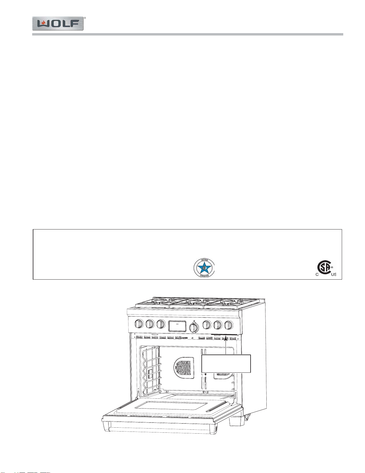
General Information International Dual Fuel (ICBDF) Series
International Dual Fuel (ICBDF) Series
INTRODUCTION
This Technical Service Manual has been compiled to provide the most recent technical service information about this
series. This information will enable the service technician to troubleshoot and diagnose malfunctions, perform nec-
essary repairs, and return the appliance to proper operational condition.
The service technician should read the complete instructions contained in this Technical Service Manual before initi-
ating any repairs on a Wolf Appliance.
* Some information in Section 3 (Operation Information) has been provided by the American Gas Association and
reprinted with AGA’s approval.
IMPORTANT SAFETY INFORMATION
Below are Product Safety Labels used in this manual.
The "Signal Words" used are WARNING or CAUTION.
When reviewing this manual, please note these differ-
ent Product Safety Labels placed at the beginning of
certain sections of this manual. You must follow the
instructions given in the boxes of the Product Safety
Labels in order to avoid personal injury and/or product
damage.
The sample Product Safety Labels below illustrate the
precautions that should be taken when the signal word
is observed.
INDICATES THAT HAZARDOUS OR UNSAFE
PRACTICES COULD RESULT IN SEVERE PERSON-
AL INJURY OR DEATH!
Indicates that hazardous or unsafe practices could
result in minor personal injury, and/or product
damage, and/or property damage!
In addition, please pay attention to the signal word
“NOTE”, which highlights information that is especially
important for the topic being covered.
TECHNICAL ASSISTANCE
If you should have any questions regarding a Wolf appli-
ance and/or this manual, please contact:
Wolf Appliance, Inc.
ATTN: Service Department
P.O. Box 44988
Madison, Wisconsin, USA, 53744-4988
Customer Service & Parts / Warranty Claims
Domestic Toll Free Phone #: (800) 332 - 9513
International Toll Charge Phone #: (608) 271 - 2233
Technical Assistance
Domestic Toll Free Phone #: (800) 919 - 8324
International Toll Charge Phone #: (608) 271 - 2233
Customer Service & Technical Assistance
International Toll Charge Facsimile #: (608) 441 - 5887
Parts / Warranty Claims
International Toll Charge Facsimile #: (608) 441 - 5886
Service Department e-mail Address
Office Hours:
7:00 AM to 6:00 PM Central Time
Monday through Friday
This manual is designed to be used by Authorized Service Personnel only. Wolf Appliance, Inc. assumes
no responsibility for any repairs made on Wolf appliance units by anyone other than Authorized Service
Technicians.
The information and images contained in this manual are the copyright property of Wolf appliance, Inc. Neither this
manual nor any information or images contained herein may be copied or used in whole or in part without the
express written consent of Wolf Appliance, Inc.©, all rights reserved.