Hatco IRBR2-6200 User manual

© 2010 atco Corporation
8.?->398#+81/=
##
8=>+66+>398+8.!:/<+>381+8?+6
9< 9./6=
I&W #07.05.260.00
989>9:/<+>/>23=/;?3:7/8>?86/==C9?2+@/
</+.+8.?8./<=>99.>2/-98>/8>=90>23=7+8?+6
+36?</>909669A>2/38=><?->398=-98>+38/.38>23=
7+8?+67+C</=?6>38=/<39?=384?<C9<./+>2%23=
7+8?+6 -98>+38= 37:9<>+8> =+0/>C 3809<7+>398
-98-/<8381>2/7+38>/8+8-/?=/+8.9:/<+>398
90>23=:<9.?->0C9?L</?8+,6/>9?8./<=>+8.>2/
-98>/8>= 90 >23= 7+8?+6 :6/+=/ ,<381 3> >9 >2/
+>>/8>39890C9?<=?:/<@3=9<//:>23=7+8?+638
+=+0/69-+>39809<0?>?</</0/</8-/
99:/<//=>//;?3:9+67/89=;?/2+C+6/E.9C
-97:</8.3.9 /6 -98>/83.9 ./ /=>/ 7+8?+6
?+6;?3/< 0+66+ /8 /6 =/1?373/8>9 ./ 6+=
38=><?--398/=-98>/83.+=/8/=>/7+8?+6:?/./
</=?6>+</8?8=/<396/=3F897?/<>/=>/7+8?+6
-98>3/8/37:9<>+8>/3809<7+-3F8=9,</=/1?<3.+.
-98-/<83/8>/+67+8>/8373/8>9?=9C9:/<+-3F8
.//=>/:<9.?->9$3?=>/.89:?/.//8>/8./</6
-98>/83.9.//=>/7+8?+6:9<0+@9<:</1?8>/+=?
=?:/<@3=9< 67+-/8+< /=>/ 7+8?+6 /8 ?8+
69-+63D+-3F8=/1?<+:+<+6+</0/</8-3+0?>?<+
#/13=>/<C9?<?83>98638/
See IMPORTANT OWNER INFORMATION section for details.

Form No. IRBRCEM-0910
2
! % %$
This manual provides the installation, safety, and operating
instructions for atco Induction Ranges. atco recommends all
installation, operating, and safety instructions appearing in this
manual be read prior to installation or operation of a unit.
Safety information that appears in this manual is identified by
the following signal word panels:
(# 38.3-+>/= + 2+D+<.9?= =3>?+>398 A23-2 30 89>
+@93./.-9?6.</=?6>38./+>29<=/<39?=384?<C
&%! 38.3-+>/= + 2+D+<.9?= =3>?+>398 A23-2 30 89>
+@93./.-9?6.</=?6>387389<9<79./<+>/384?<C
!%3=?=/.>9+..</==:<+->3-/=89></6+>/.>9:/<=98+6
384?<C
NOTICE
CAUTION
WARNING
%#!&%!
atco Induction Ranges offer a safe, quick, efficient, and
attractive way to prepare foods in commercial kitchens as well
as display cooking locations (omelet bars, buffets, etc...). The
high efficiency, accuracy, and speed of induction cooking make
atco Induction Ranges the perfect choice for quality
foodservice organizations.
Induction cooking relies on the creation of a magnetic field
between the induction coils below the glass surface of the unit
and an “induction-ready” pan sitting on top of the glass surface.
This magnetic field generates induction currents in the base of
the pan, which heat the pan instantly. That heat then is
transferred to the pan contents. Since the magnetic field exists
only between the induction coils and a magnetic material
(ferrous material), the glass surface between the two does not
become heated, eliminating heat loss and increasing efficiency.
When the magnetic field is “broken” by turning off the unit or
removing the pan, heat generation stops instantly.
atco Induction Ranges are products of extensive research and
field testing. The materials used were selected for maximum
durability, attractive appearance, and optimum performance.
Every unit is inspected and tested thoroughly prior to shipment.
7:9<>+8>!A8/<809<7+>398
8><9.?->398
7:9<>+8>$+0/>C809<7+>398
9./6/=-<3:>398
9./6/=318+>398
$:/-303-+>398=
Plug Configurations .........................................................4
Electrical Rating Chart.....................................................4
Dimensions — Induction Range......................................5
Dimensions — Remote Mounted Control Panel .............5
8=>+66+>398
General............................................................................6
Installing Built-In Models..................................................6
!:/<+>398
General............................................................................7
Pan Specifications ...........................................................7
Startup .............................................................................8
Shutdown.........................................................................8
+38>/8+8-/
General............................................................................9
Daily Cleaning .................................................................9
Cleaning the Air Inlet Filters ............................................9
%<9?,6/=299>381?3./
373>/.(+<<+8>C
$/<@3-/809<7+>398
"!#% %!( # !#%!
Record the model number, serial number (located on the
bottom of the unit), voltage, and purchase date of the unit in
the spaces below. Please have this information available when
calling atco for service assistance.
Model No. ____________________________________
Serial No. ____________________________________
Voltage ______________________________________
Date of Purchase ______________________________
#/13=>/<C9?<?83>
Completing online warranty registration will prevent delay in
obtaining warranty coverage. Access the atco website at
AAA2+>-9-9<:-97, select the Parts & Servi e pull-down
menu, and click on “Warranty Registration”.
Business 8:00 AM to 5:00 PM
ours: Central Standard Time (C.S.T.)
(Summer ours: June to September –
8:00 AM to 5:00 PM C.S.T.
Monday through Thursday
8:00 AM to 2:30 PM C.S.T. Friday)
Telephone: (414) 671-6350
E-mail: part[email protected]
Fax: (414) 671-3976 (Parts and Service)
Additional information can be found by visiting our web site at
AAA2+>-9-9<:-97.

Form No. IRBRCEM-0910 3
"!#% %$%) !#%!
+5/=?</+669:/<+>9<=2+@/,//838=><?->/.98>2/=+0/
+8.:<9:/<?=/90>2/?83>
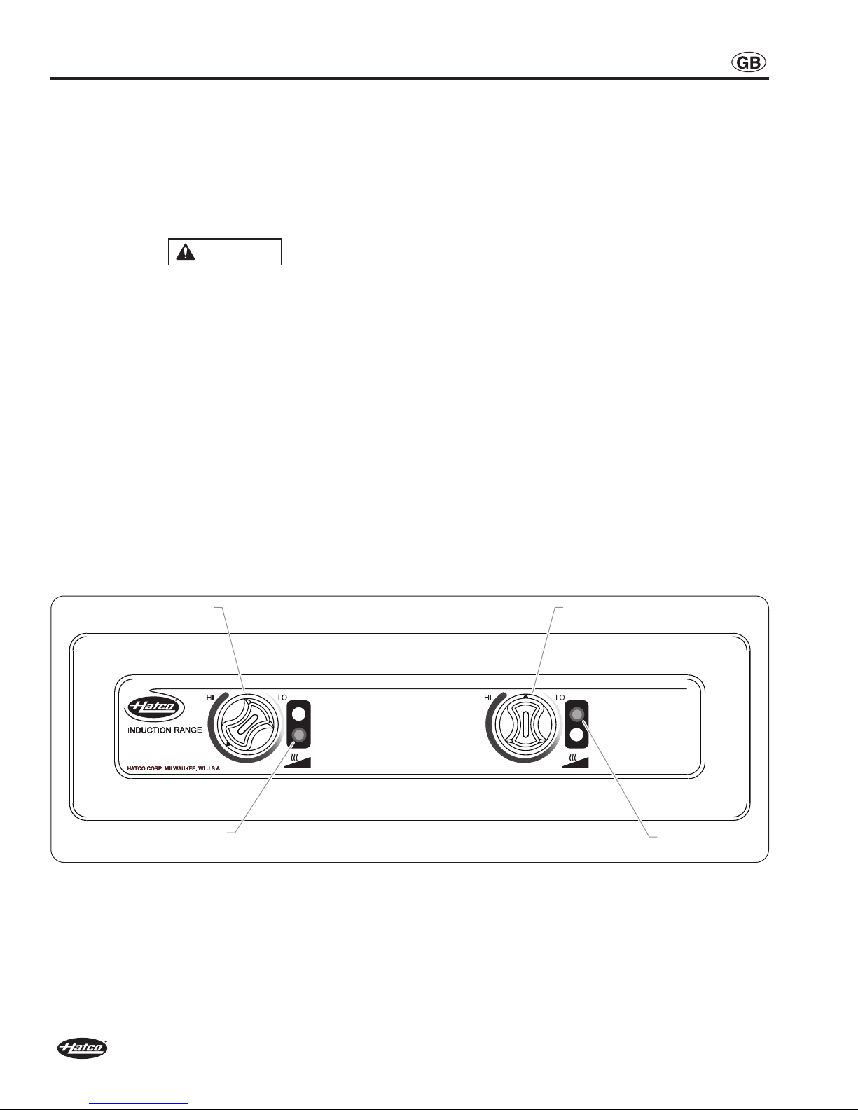
%#! % %## *#%23=?83>
1/8/<+>/=-69=/<+81//6/-><97+18/>3-03/6.=>2+=,//8
./=318/. >9 7//> >2/ +::63-+,6/ =>+8.+<.= 09< 898
38>/<0/</8-/A3>29>2/</6/-><983-./@3-/=+5/=?</9>2/<
/6/-><983-./@3-/=38>2/@3-383>C 38-6?.381:+-/7+5/<=
+8.9>2/< +->3@/ 37:6+8>= 2+@/,//8 ./=318/.>9 7//>
>2/3<-9<</=:98.381+::63-+,6/=>+8.+<.=
%23=?83>7?=>,/=/<@3-/.,C;?+6303/.:/<=988/6986C
$/<@3-/ ,C ?8;?+6303/. :/<=988/6 7+C 6/+. >9 /6/-><3-
=29-59<,?<8
%23= ?83> 2+= 89 J?=/<=/<@3-/+,6/K :+<>= 0 =/<@3-/ 3=
</;?3</.98>23=?83>-98>+->+8?>29<3D/.+>-9$/<@3-/
1/8> 9< -98>+-> >2/ +>-9 $/<@3-/ /:+<>7/8> +>
0+B
&# *#
H 9 89> 6/+@/ 7/>+6 9,4/->= 9< ?>/8=36= 98 9< 8/+<
38.?->398<+81/%2/C7+C,/-97/29>
H &=/ -+?>398 A2/8 A/+<381 <381= A+>-2/= 9< 9>2/<
0/<<9?= 9,4/->= +<9?8. 38.?->398 <+81/ %2/C 7+C
,/-97/29>
H $97//B>/<39<=?<0+-/=98?83>A3661/>29>&=/-+?>398
A2/8>9?-2381>2/=/+</+=
9 89> ,69-5 9< </=><3-> +3< 069A >9 +3< 386/> 036>/<= 98
,9>>9790?83>
989>=>9</+8C>238198>9:90?83>
9-+>/?83>+>>2/:<9:/<-9?8>/<2/312>38+8+</+>2+>3=
-98@/83/8>09<?=/%2/69-+>398=29?6.,/6/@/6>9:</@/8>
>2/?83>9<3>=-98>/8>=0<970+66381+--3./8>+66C+8.=><981
/89?12>9=?::9<>>2/A/312>90>2/?83>+8.-98>/8>=
(3:/?:+66=:366=+8.=:6+=2/=377/.3+>/6C+5/=?</?83>
3=.<C,/09</?=381989>+669A63;?3.>9<?838>9+3<386/>
036>/<98,9>>9790?83>
/@/<?=/+6?738?7093698>2/38.?->398<+81/6?738?7
0936A3667/6>+8..+7+1/>2/?83>
9 89> :6+-/ 9,4/->= A3>2 7+18/>3- :<9:/<>3/= -</.3>
-+<.= -+==/>>/ >+:/= />- 98 9< 8/+< ?83> .?<381
9:/<+>398
&=/986CA3:/=:+.=+8.-6/+8/<=./=318/.=:/-303-+66C
09<-6/+8381-/<+73-16+===?<0+-/=
989>?=//B-/==3@/09<-/A2/8>312>/838179?8>3818?>=
98,?36>38?83>=%23=7+C.+7+1/?83>+8.9<-9?8>/<>9:
&=/898+,<+=3@/-6/+8/<=986C,<+=3@/-6/+8/<=-9?6.
=-<+>-2>2/0383=290>2/?83>7+<<3813>=+::/+<+8-/+8.
7+53813>=?=-/:>3,6/>9=936+--?7?6+>398
NOTICE
CAUTION
WARNING
%#$!*#
H &83>= =?::63/. A3>29?> +8 /6/-><3-+6 :6?1 </;?3</ +
2+<.A3</. -988/->398 >9 98=3>/ /6/-><3-+6 =C=>/7
988/->3987?=>,/:<9:/<6C1<9?8./.+8.90-9<</->
@96>+1/ =3D/ +8. -98031?<+>398 09< /6/-><3-+6
=:/-303-+>398=90?83>98>+->+;?+6303/./6/-><3-3+8>9
./>/<738/+8.:/<09<7:<9:/</6/-><3-+6-988/->398
H &83> 7?=> ,/ 38=>+66/. ,C + ;?+6303/. /6/-><3-3+8
8=>+66+>3987?=>-9809<7>9+6669-+6/6/-><3-+6-9./=
8=>+66+>398 ,C ?8;?+6303/. :/<=988/6 A366 @93. ?83>
A+<<+8>C+8.7+C6/+.>9/6/-><3-=29-59<,?<8+=A/66
+=.+7+1/>9?83>+8.9<3>==?<<9?8.381=
H %?<8 ! :9A/< =A3>-2 >?<8 900 :9A/< +> -3<-?3>
,</+5/<+8.+669A?83>>9-996,/09</:/<09<7381+8C
7+38>/8+8-/9<-6/+8381
H ! !%=?,7/<1/9<=+>?<+>/A3>2A+>/<&83>3=89>
A+>/<:<990989>9:/<+>/30?83>2+=,//8=?,7/<1/.
9<=+>?<+>/.A3>2A+>/<
H #/79>/79?8>/.-98><96:+8/67?=>,/79?8>/.98+
@/<>3-+6A+66+8.38=>+66/.38@/<>3-+6:9=3>3989?8>381
-98><96 :+8/6 38 29<3D98>+6 :9=3>398 7+C </=?6> 38
-966/->3989063;?3.=+8.6/+.>9+8/6/-><3-=29-5
H &83>3= 89> A/+>2/<:<9909-+>/?83>38.99<=A2/</
+7,3/8>+3<>/7:/<+>?</3=+73837?790GG
H 989>=>/+7-6/+89<?=//B-/==3@/A+>/<98>2/?83>
H %23=?83>3=89>J4/>:<990K-98=><?->398989>?=/4/>
-6/+8=:<+C>9-6/+8>23=?83>
H 989>-6/+8?83>A2/83>3=/8/<13D/.9<29>
H 989>+669A63;?3.=>9=:36638>9>2/?83>
H &=/ 986C /8?38/ +>-9 #/:6+-/7/8> "+<>= A2/8
=/<@3-/ 3= </;?3</. +36?</ >9 ?=/ /8?38/ +>-9
#/:6+-/7/8> "+<>= A366 @93. +66 A+<<+8>3/= +8. 7+C
=?,4/-> 9:/<+>9<= 90 >2/ /;?3:7/8> >9 2+D+<.9?=
/6/-><3-+6@96>+1/</=?6>38138/6/-><3-+6=29-59<,?<8
/8?38/ +>-9 #/:6+-/7/8> "+<>= +</ =:/-303/. >9
9:/<+>/=+0/6C38>2//8@3<987/8>=38A23-2>2/C+</
?=/.$97/+0>/<7+<5/>9<1/8/<3-</:6+-/7/8>:+<>=
.989>2+@/>2/-2+<+->/<3=>3-=>2+>A366+669A>2/7>9
9:/<+>/=+0/6C38+>-9/;?3:7/8>
#*#
H 9-+>/?83>+73837?79077M0<97-97,?=>3,6/
A+66= +8. 7+>/<3+6= 0 =+0/ .3=>+8-/= +</ 89>
7+38>+38/..3=-969<+>3989<-97,?=>398-9?6.9--?<
H 989>:6+-/?83>8/+<9<?8./<8/+>2-?<>+38=9<9>2/<
-97,?=>3,6/7+>/<3+6=>/7=8/+<9<+,9@/?83>-9?6.
-+>-203</-+?=381384?<C+8.9<.+7+1/>9?83>
989>2/+>?89:/8/.-98>+38/<=90099.98?83>$/+6/.
2/+>/.-98>+38/<=7+C,?<=>9:/8
%23=?83>3=89>38>/8./.09<?=/,C-236.</89<:/<=98=
A3>2 </.?-/. :2C=3-+6 =/8=9<C 9< 7/8>+6 -+:+,363>3/=
8=?</:<9:/<=?:/<@3=39890-236.</8+8.5//:>2/7+A+C
0<97>2/?83>
WARNING
#/+.>2/09669A38137:9<>+8>=+0/>C3809<7+>398,/09</?=381>23=/;?3:7/8>>9+@93.=/<39?=384?<C9<./+>2+8.
>9+@93..+7+1/>9/;?3:7/8>9<:<9:/<>C

Form No. IRBRCEM-0910
4
!$#"%!
!$ %!
$"%! $
The atco Model IRBR2-6200 Induction Range is a built-in hob
equipped with two induction coils underneath a ceramic glass
surface. Dual coils enable the use of two pans on a single hob.
The induction coils adapt to the induction-ready pan size to
ensure even heat distribution for even cooking.
Each unit features a remote mounted control panel with infinite
heat controls and an attached 1829 mm (72″) power cord (plug
not included, hardwired connection required). Refer to the
INSTALLATION section of this manual for details on installing
a built-in hob.
NOTE: Refer to “Pan Spe ifi ations” in the OPERATION
se tion of this manual for details on “indu tion-ready”
pans, pans not suitable for indu tion ooking, and pan
sizes.
atco Induction Ranges have several safeguards built in to
each unit that ensure protection to the unit as well as the
operators.
• A dual fan ventilation system for each coil ensures that the
electronic circuits in the unit do no overheat. A temperature
probe monitors the electronic circuits and will signal the
unit to shut down if the circuits get too hot.
• A temperature probe in each cooking zone monitors the
zone temperature. This probe detects overheating in the
cooking zone due to an empty pan.
• A sensor in each cooking zone detects when a small,
ferrous object (such as a fork, spoon, or ring) is placed on
the unit. The corresponding coil indicator light on the
control panel will flash and the unit will not operate.
Figure 1. Model IRBR2-6200
Induction
Range
Remote Mounted
Control Panel
9./6 '96>+1/ (+>>= 7:= "6?198031?<+>398 $23::381(/312>
IRBR2-6200 230 (CE) 6200 27.0 No Plug/ ardwired 15 kg (33 lbs.)
6/-><3-+6#+>3812+<>
Units are supplied from the factory with an electrical cord only.
A qualified electrician must connect the unit to the on-site
electrical system.
NOTE: The spe ifi ation label is lo ated on the bottom of the
unit. See label for serial number and verifi ation of unit
ele tri al information.
NOTE: Shipping weight in ludes pa kaging.
I R B R 2 - XXXX
Induction Range Unit Wattage
Two Coils
Built-In
Remote Mounted Controls
Figure 2. Model Designation
%# $! *# &83>= =?::63/. A3>29?> +8
/6/-><3-+6:6?1</;?3</+2+<.A3</.-988/->398>998=3>/
/6/-><3-+6=C=>/7988/->3987?=>,/:<9:/<6C1<9?8./.
+8.90-9<</->@96>+1/=3D/+8.-98031?<+>39809</6/-><3-+6
=:/-303-+>398= 90 ?83> 98>+-> + ;?+6303/. /6/-><3-3+8 >9
./>/<738/+8.:/<09<7:<9:/</6/-><3-+6-988/->398
WARNING

Form No. IRBRCEM-0910 5
$"%! $
A
C
B
E
D
Front View
Side View
Top View
F
G
Figure 3. Dimensions — Induction Range
A
C
D
Front View
B
E
Side View
Figure 4. Dimensions — Remote Mounted Control Panel
37/8=398=I8.?->398#+81/
(3.>2 /:>2 /312> ?36>8 ?36>8 <98>936 #/+<936
9./6 (3.>2 /:>2 3+7/>/< 3+7/>/<
IRBR2-6200 440 mm 580 mm 105 mm 369 mm 500 mm 232 mm 232 mm
(17-3/8″) (22-7/8″) (4-3/16") (14-9/16") (19-3/4") (9-1/4") (9-1/4")
37/8=398=I#/79>/9?8>/.98><96"+8/6
(3.>2 /:>2 /312> ?36>8 ?36>8
(3.>2 /:>2
400 mm 110 mm 85 mm 250 mm 70 mm
(15-3/4″) (4-3/8″) (3-3/8") (9-7/8") (2-3/4")

Form No. IRBRCEM-0910
6
$%%!
/8/<+6
Induction Ranges are shipped completely assembled and
ready for use. Built-in units require installation into a non-ferrous
countertop (see procedure in this section). Care should be
taken when unpacking the shipping carton to avoid damage to
the unit and components enclosed.
%#$!*#
H &83>3=89>A/+>2/<:<990 9-+>/?83>38.99<=A2/</
+7,3/8>+3<>/7:/<+>?</3=+73837?790GG
H #/79>/79?8>/.-98><96:+8/67?=>,/79?8>/.98+
@/<>3-+6A+66+8.38=>+66/.38@/<>3-+6:9=3>3989?8>381
-98><96 :+8/6 38 29<3D98>+6 :9=3>398 7+C </=?6> 38
-966/->3989063;?3.=+8.6/+.>9+8/6/-><3-=29-5
#*#
H 9-+>/?83>+73837?79077M0<97-97,?=>3,6/
A+66= +8. 7+>/<3+6= 0 =+0/ .3=>+8-/= +</ 89>
7+38>+38/..3=-969<+>3989<-97,?=>398-9?6.9--?<
H 989>:6+-/?83>8/+<9<?8./<8/+>2-?<>+38=9<9>2/<
-97,?=>3,6/7+>/<3+6=>/7=8/+<9<+,9@/?83>-9?6.
-+>-203</-+?=381384?<C+8.9<.+7+1/>9?83>
9 89> ,69-5 9< </=><3-> +3< 069A >9 +3< 386/> 036>/<= 98
,9>>9790?83>
1. Remove the unit from the carton.
2. Remove the information packet from the carton.
3. Remove tape and protective packaging from all surfaces of
unit.
NOTE: To prevent delay in obtaining warranty overage,
omplete online warranty registration. See the
IMPORTANT OWNER INFORMATION se tion for
details.
4. Determine and prepare an appropriate installation location.
Make sure the installation location:
• is level and made of non-combustible, non-ferrous
material.
• is strong enough to support the unit and its contents.
• provides a minimum of 51 mm (2″) clearance from
combustible materials.
8=>+66381?36>89./6=
IRBR2-6200 models are built-in hobs that require installation
into a countertop before operation.
NOTE: Make sure that the installation lo ation allows a ess to
the underside of the unit for maintenan e and leaning
after it has been pla ed into the ountertop.
CAUTION
WARNING
1. Carefully measure and cut
the appropriate opening in
the countertop for the
induction range. Refer to
the illustration for
dimensions.
NOTE: Make sure a minimum
51 mm (2") learan e
will be available between
the sides of the unit and
any interior surfa e. A
minimum of 128 mm [5"]
will be needed below the
ountertop surfa e for
the height of the unit.
Figure 5. Countertop Cutout
2. If necessary, make structural modifications or add bracing
underneath the countertop to ensure the countertop will
support the weight of the unit and its contents.
NOTE: The ountertop must be level to ensure proper
operation of the indu tion range.
3. Carefully measure and cut the appropriate opening in the
vertical surface where the remote mounted control panel
will be installed. The control panel must be installed within
400 mm (15-3/4″) of the induction range. Refer to the
illustration below for dimensions.
Figure 6. Remote Mounted Control Panel Cutout
4. Carefully measure and drill six 5mm (3/16″) holes around
the control panel cutout for the control mounting studs
(M4 thread). Refer to the illustration below for dimensions.
Figure 7. Control Mounting Stud Locations
5. Make sure the cabinetry provides proper ventilation with
external air to the underside of the unit. If necessary, cut
ventilation openings in the cabinetry to provide the
ventilation. Louvered or grill-style panels should be
installed in the openings.
6. Make sure a grounded electrical connection of the correct
voltage and size is within 1829 mm (72″) inside the
mounting location for the unit. See the SPECIFICATIONS
section for details.
7. Disconnect the control wires from the bottom of the
induction range.
370 mm
(14-9/16″) 76mm
(3″)
Vertical SurfaceVertical SurfaceVertical Surface
90 mm
(3-1/2″) 10 mm
(3/8″)
15 mm
(9/16″)
Ø5 mm
(3/16″)
185 mm
(7-1/4″) 185 mm
(7-1/4″)
Control panel faceplate outline.
400 mm
(15-3/4″)
540 mm
(21-1/4″)
Induction Range Countertop
Cutout Dimensions

Form No. IRBRCEM-0910 7
$%%!
!"#%!
8. Apply a bead of silicone sealant onto the countertop
material around the induction range cutout opening.
9. Carefully lower the induction range into the countertop
cutout, making sure the power cord does not get pinched.
10. Assemble the mounting clips and mounting nuts to the
eight mounting studs on the underside of the induction
range.
Figure 8. Installing the Unit into the Countertop
NOTE: Mounting lips and mounting nuts not supplied—
provided by installer.
11. Tighten and readjust the mounting nuts underneath the
induction range until the flange lies flat on the countertop.
989>?=//B-/==3@/09<-/A2/8>312>/838179?8>3818?>=
98,?36>38?83>=%23=7+C.+7+1/?83>+8.9<-9?8>/<>9:
12. Apply a bead of silicone sealant onto the vertical surface
around the control panel cutout opening.
13. Install the remote mounted control panel into the vertical
surface cutout, aligning the control mounting studs with the
pre-drilled holes. Make sure the control wires are fed
through the opening first and that they do not get pinched.
Mounting Nut
Mounting Stud
(M4 Thread)
Apply a bead of silicone sealant
between the countertop material
and the flange on the unit.
Flange (Front View)
Mounting Clip
Countertop
Material
NOTICE
14. Thread six mounting nuts (M4 thread) onto the control
mounting studs on the back of the remote mounted control
panel.
15. Provide separation underneath the induction range
between the cooling air inlet filters and the exhaust fans.
This is necessary to prevent hot exhaust air from being
drawn back into the unit through the cooling air inlets, which
could cause the unit to overheat and stop working.
NOTE: Flexible vent tubing is provided to onne t to ea h air
inlet filter to provide dedi ated ooling air, if ne essary.
Figure 9. Inlet and Exhaust Air Separation
16. Route and reconnect the control wires to the bottom of the
induction range.
&83>7?=>,/38=>+66/.,C+;?+6303/./6/-><3-3+88=>+66+>398
7?=>-9809<7>9+6669-+6/6/-><3-+6-9./=8=>+66+>398,C
?8;?+6303/.:/<=988/6A366@93.?83>A+<<+8>C+8.7+C6/+.
>9/6/-><3-=29-59<,?<8+=A/66+=.+7+1/>9?83>+8.9<
3>==?<<9?8.381=
17. Make the appropriate electrical connections between the
power cord and the onsite electrical supply.
Grill Panel
(Min. 150 cm²
[60 in²])
Front
Air Inlet Filter
Rear
Air Inlet Filter
(Front View) Front and Rear
Exhaust Fans
Separation
(non-combustible material)
WARNING
/8/<+6
IRBR2-6200 Induction Ranges are dual-coil hobs. The front coil
and rear coil on the hobs are capable of operating
independently as well as together. Use the following information
and procedures to operate an IRBR2-6200 atco Induction
Range.
#/+. +66 =+0/>C 7/==+1/= 38 >2/ "!#% % $%)
!#%! =/->398,/09</9:/<+>381>23=/;?3:7/8>
"+8$:/-303-+>398=
Pans used with an induction range must meet the following
specifications:
• Made of material with magnetic properties (ferrous
material)
- Enamelled Steel Pans
- Cast Iron Pans
- Stainless Steel Pans
- Aluminum Pans w/ferrous base
WARNING
• Proper size (measurements given are the manufacturer’s
pan size, not the pan bottom diameter)
- Front Coil = Min. 152 mm (6″) to Max. 254 mm (10″)
- Rear Coil = Min. 152 mm (6″) to Max. 254 mm (10″)
NOTE: Pan bottoms should not extend more than 13 mm (1/2″)
beyond the ooking zone patterns on the glass surfa e.
• Flat bottom
The following pans -+889> be used with an induction range:
• Glass Pans
• Aluminum Pans w/o ferrous base
• Earthenware Pans
• Ceramic Pans
• Copper Pans
NOTE: The indu tion range automati ally dete ts if a pan is
indu tion-ready. If a pan is pla ed on the unit that is not
indu tion-ready, the orresponding oil indi ator light
will flash and the unit will not operate.
ontinued...

Form No. IRBRCEM-0910
8
!"#%!
$>+<>?:
Operate the front and rear coils independently when only one
pan is being used or together when two pans are being used.
1. Before turning on the unit each day, clean the glass surface
using an appropriate cleaning wipe, damp paper towel, or
a damp cloth. &%! (3:/?:+66=:366=+8.=:6+=2/=
377/.3+>/6C+5/=?</?83>3=.<C,/09</?=3819
89>+669A63;?3.>9<?838>9+3<386/>036>/<98,9>>9790
?83>
&# *#
H 989>6/+@/7/>+69,4/->=9<?>/8=36=989<8/+<>2/
38.?->398<+81/%2/C7+C,/-97/29>
H &=/ -+?>398 A2/8 A/+<381 <381= A+>-2/= 9< 9>2/<
0/<<9?= 9,4/->= +<9?8. 38.?->398 <+81/ %2/C 7+C
,/-97/29>
H $97//B>/<39<=?<0+-/=98>2/?83>A3661/>29>&=/
-+?>398A2/8>9?-2381>2/=/+</+=
2. Place an induction-ready pan(s) on the desired coil(s). The
induction range will not operate without a pan centered
inside the cooking zone pattern on the glass surface.
3. Turn the appropriate Coil eat Control to the desired
setting for the front coil, rear coil, or both coils to turn on the
induction range.
NOTE: The setting of the Coil Heat Controls an be hanged at
any time during operation.
CAUTION
$2?>.9A8
1. Turn the appropriate Coil eat Control to the “off” position
to turn off the front coil, rear coil, or both.
2. Remove pan(s) from coil(s).
NOTE: Heat generation will stop automati ally whenever a pan
is removed from the glass surfa e. The orresponding
oil indi ator light will flash until the pan is repla ed and
heat generation resumes.
3. Perform the procedure in the “Cleaning and Maintenance”
section of this guide.
Rear Coil Heat Control
("off" position)
Front Coil
Heat Control
Front Coil
Indicator Light Rear Coil
Indicator Light
Figure 10. IRBR2-6200 Control Panel

Form No. IRBRCEM-0910 9
%
/8/<+6
atco Induction Ranges are designed for maximum durability
and performance with minimum maintenance.
%#$!*#
H %?<8 ! :9A/< =A3>-2 >?<8 900 :9A/< +> -3<-?3>
,</+5/<+8.+669A?83>>9-996,/09</:/<09<7381+8C
7+38>/8+8-/9<-6/+8381
H ! !%=?,7/<1/9<=+>?<+>/A3>2A+>/<&83>3=89>
A+>/<:<990989>9:/<+>/30?83>2+=,//8=?,7/<1/.
9<=+>?<+>/.A3>2A+>/<
H 989>=>/+7-6/+89<?=//B-/==3@/A+>/<98>2/?83>
H %23=?83>3=89>J4/>:<990K-98=><?->398989>?=/4/>
-6/+8=:<+C>9-6/+8>23=?83>
H 989>-6/+8?83>A2/83>3=/8/<13D/.9<29>
%23= ?83> 2+= 89 J?=/<=/<@3-/+,6/K :+<>= 0 =/<@3-/ 3=
</;?3</.98>23=?83>-98>+->+8?>29<3D/.+>-9$/<@3-/
1/8> 9< -98>+-> >2/ +>-9 $/<@3-/ /:+<>7/8> +>
0+B
(3:/?:+66=:366=+8.=:6+=2/=377/.3+>/6C+5/=?</?83>
3=.<C,/09</?=381989>+669A63;?3.>9<?838>9+3<386/>
036>/<98,9>>9790?83>
+36C6/+8381
To maintain performance and preserve the finish of the
induction range, clean the unit daily. Make sure to use only
wipes, pads, and cleaners designed specifically for cleaning
ceramic glass surfaces.
1. Turn off the unit and allow to cool.
2. Remove and wash all food pans.
3. Clean the glass surface using an appropriate cleaning
wipe, damp paper towel, or damp cloth.
• For tough stains and metal marks, use a drop of ceramic
glass cleaner and paper towel.
• For water and scale marks, use a few drops of white
vinegar and paper towel.
&=/898+,<+=3@/-6/+8/<=986C,<+=3@/-6/+8/<=-9?6.
=-<+>-2>2/0383=290>2/?83>7+<<3813>=+::/+<+8-/+8.
7+53813>=?=-/:>3,6/>9=936+--?7?6+>398
4. Clean the metal surfaces using a clean, soft cloth and mild
detergent.
WARNING
CAUTION
NOTICE
6/+8381>2/3<86/>36>/<=
The air inlet filters on the bottom of the unit should be removed
and cleaned monthly. Use the following procedure to clean the
filters.
1. Turn off the unit, remove any food pans, and turn off power
at the circuit breaker .Allow the unit to cool.
2. Access the air inlet filters on the bottom of the unit.
3. For each air inlet filter:
a. Remove the frame screw on the filter frame.
b. Lower the filter frame and air inlet filter off of the unit.
c. Clean the air inlet filter with soapy water.
d. Allow the air inlet filter to dry completely.
e. Place the air inlet filter inside the filter frame and install
onto the bottom of the unit. Install the frame by inserting
the tabs on the filter frame into the tab slots on the
bottom of the unit.
f. Insert the frame screw and tighten securely.
Figure 11. Removing the Air Inlet Filters
Frame
Screw
Rear Coil
Air Inlet Filter
Rear Coil
Filter Frame
Tab
Front Coil
Air Inlet
Filter
Front Coil
Filter
Frame
Tab Slot

$C7:>97 "<9,+,6/+?=/ 9<</->3@/->398
Unit does not turn on. No power to unit. Make sure unit is connected to the proper power supply
(see SPECIFICATIONS section). Check circuit breaker
and reset as necessary. Check for damage to power
cord. Check electrical supply.
Controls defective. Contact Authorized Service Agent or atco for assistance.
A coil indicator light is flashing
and the unit will not heat.
Pan being used is not induction-
ready.
Use an induction-ready pan (see “Pan Specifications” in
the OPERATION section of this manual).
Unit stops working during
operation.
Unit has overheated. Make sure installation location allows proper ventilation
underneath the unit:
• Make sure air inlet filters and exhaust fans are not
blocked.
• Make sure air inlet filters are clean.
• Make sure installation of built-in unit provides proper
separation between cooling air (air inlet) and hot
exhaust air (exhaust fan).
• Install flexible vent tubing (included with unit) to rear
air inlet filter to provide dedicated cooling air to unit.
Exhaust fan(s) continues to run
after unit has been turned off.
Cooling of the unit not complete. No action necessary. This is a normal function of the unit.
Exhaust fan starts for a few
seconds after plugging in unit.
Automatic testing of unit. No action necessary. This is a normal function of the unit.
Form No. IRBRCEM-0910
10
%#!&$!!% &
%23=?83>7?=>,/=/<@3-/.,C;?+6303/.:/<=988/6986C
$/<@3-/ ,C ?8;?+6303/. :/<=988/6 7+C 6/+. >9 /6/-><3-
=29-59<,?<8
WARNING
%#$!*#%?<8!:9A/<=A3>-2>?<8
900:9A/<+>-3<-?3>,</+5/<+8.+669A?83>>9-996,/09</
:/<09<7381+8C7+38>/8+8-/9<-6/+8381
WARNING

Form No. IRBRCEM-0910 11
%(## %)
$#' !#%!
(+<<+8>C==?/=I &83>/.381.97
The warranty on atco Induction Ranges is for one year from
date of purchase or eighteen months from date of shipping from
atco, whichever occurs first.
If you experience an issue with an Induction Range during the
warranty period, contact the +<</8<9?: at:
%/6/:298/
When contacting the Marren Group for warranty assistance,
please supply the following information:
• Model of unit
• Serial number (located on the bottom of the unit)
• Specific problem with the unit
• Date of purchase
• Name of business
• Shipping address
• Contact name and telephone number
98(+<<+8>C==?/=
If you experience a non-warranty issue that requires assistance,
please contact the Marren Group.
"#!&%(## %)
atco warrants the products that it manufactures (the
“Products”) to be free from defects in materials and
workmanship, under normal use and service, for a period of
one (1) year from the date of purchase when installed and
maintained in accordance with atco’s written instructions or
18 months from the date of shipment from atco. Buyer must
establish the Product’s purchase date by returning atco’s
Warranty Registration Card or by other means satisfactory to
atco in its sole discretion.
atco warrants the following Product components to be free
from defects in materials and workmanship from the date of
purchase (subject to the foregoing conditions) for the period(s)
of time and on the conditions listed below:
+ !8/)/+<"+<>=+8.+,9<"&$!8/
..3>398+6)/+<"+<>=!86C(+<<+8>C
Conveyor Toaster Elements (metal sheathed)
Drawer Warmer Elements (metal sheathed)
Drawer Warmer Drawer Rollers and Slides
Food Warmer Elements (metal sheathed)
Display Warmer Elements (metal sheathed air heating)
olding Cabinet Elements (metal sheathed air heating)
Built-In eated Well Elements — WB and WBI Series
(metal sheathed)
, !8/)/+<"+<>=+8.+,9<"&$9?<
)/+<="+<>=!86C(+<<+8>C98
:<9<+>/.>/<7=>2+>+>-9A366/B:6+38
+>?C/<L=</;?/=>
3CS and FR Tanks
- !8/)/+<"+<>=+8.+,9<"&$ 38/
)/+<="+<>=!86C(+<<+8>C98
Electric Booster eater Tanks
Gas Booster eater Tanks
. 38/>C+C"+<>=!86C(+<<+8>C
Replacement Parts
T E FOREGOING WARRANTIES ARE EXCLUSIVE AND IN
LIEU OF ANY OT ER WARRANTY, EXPRESSED OR
IMPLIED, INCLUDING BUT NOT LIMITED TO ANY IMPLIED
WARRANTY OF MERC ANTABILITY OR FITNESS FOR A
PARTICULAR PURPOSE OR PATENT OR OT ER
INTELLECTUAL PROPERTY RIG T INFRINGEMENT.
Without limiting the generality of the foregoing, SUC
WARRANTIES DO NOT COVER: Coated incandescent light
bulbs, fluorescent lights, heat lamp bulbs, coated halogen light
bulbs, halogen heat lamp bulbs, glass components, and fuses;
Product failure in booster tank, fin tube heat exchanger, or other
water heating equipment caused by liming, sediment buildup,
chemical attack, or freezing; or Product misuse, tampering or
misapplication, improper installation, or application of improper
voltage.
%%! !#$ $
atco’s liability and Buyer’s exclusive remedy hereunder will be
limited solely, at atco’s option, to repair or replacement using
new or refurbished parts or Product by atco or a atco-
authorized service agency (other than where Buyer is located
outside of the United States, Canada, United Kingdom, or
Australia, in which case atco’s liability and Buyer’s exclusive
remedy hereunder will be limited solely to replacement of part
under warranty) with respect to any claim made within the
applicable warranty period referred to above. atco reserves
the right to accept or reject any such claim in whole or in part.
In the context of this Limited Warranty, “refurbished” means a
part or Product that has been returned to its original
specifications by atco or a atco-authorized service agency.
atco will not accept the return of any Product without prior
written approval from atco, and all such approved returns shall
be made at Buyer’s sole expense. ATCO WILL NOT BE
LIABLE, UNDER ANY CIRCUMSTANCES, FOR
CONSEQUENTIAL OR INCIDENTAL DAMAGES, INCLUDING
BUT NOT LIMITED TO LABOR COSTS OR LOST PROFITS
RESULTING FROM T E USE OF OR INABILITY TO USE T E
PRODUCTS OR FROM T E PRODUCTS BEING
INCORPORATED IN OR BECOMING A COMPONENT OF
ANY OT ER PRODUCT OR GOODS.

12 P/N 07.04.553.00 Form No. IRBRCEM-0910
Printed in U.S.A. September 2010
HATCO CORPORATION
P.O. Box 340500
Milwaukee, WI 53234-0500 U.S.A.
Telephone (414) 671-6350
International Fax (414) 671-3976
www.hatcocorp.com
%!&%!#*"#%$$%#&%!#$
&83>/.381.97
Marren Group
Northants +44(0)1933 666233
#/13=>/<C9?<?83>98638/
See IMPORTANT OWNER INFORMATION
section for details.
Table of contents
Other Hatco Range manuals
Popular Range manuals by other brands

Dacor
Dacor Renaissance RNRP36GS installation instructions

Daikin
Daikin VRV FXDQ-PDVE engineering data

Whirlpool
Whirlpool W10477533B installation instructions

Electrolux
Electrolux EW30ES65GS - 30" Slide-In Electric Range Wiring diagram

Verona
Verona VEFSEE 304 P SERIES installation instructions

GE
GE Profile PGS968DEP Dimensions and installation information