manuals.online logo
Brands
  1. Home
  2. •
  3. Brands
  4. •
  5. Subaru
  6. •
  7. Automobile
  8. •
  9. Subaru 2006 Impreza Setup guide

Subaru 2006 Impreza Setup guide

ABS (DIAGNOSTICS)
ABS(diag)-2
ABS (DIAGNOSTICS)
Basic Diagnostic Procedure
1. Basic Diagnostic Procedure
A: PROCEDURE
CAUTION:
Remove foreign matters (dust, water, oil, etc.) from the ABSCM&H/U connector during removal and
installation.
NOTE:
•To check harness for broken wires or short circuits, shake trouble spot or connector.
•Refer to “Check List for Interview”. <Ref. to ABS(diag)-4, Check List for Interview.>
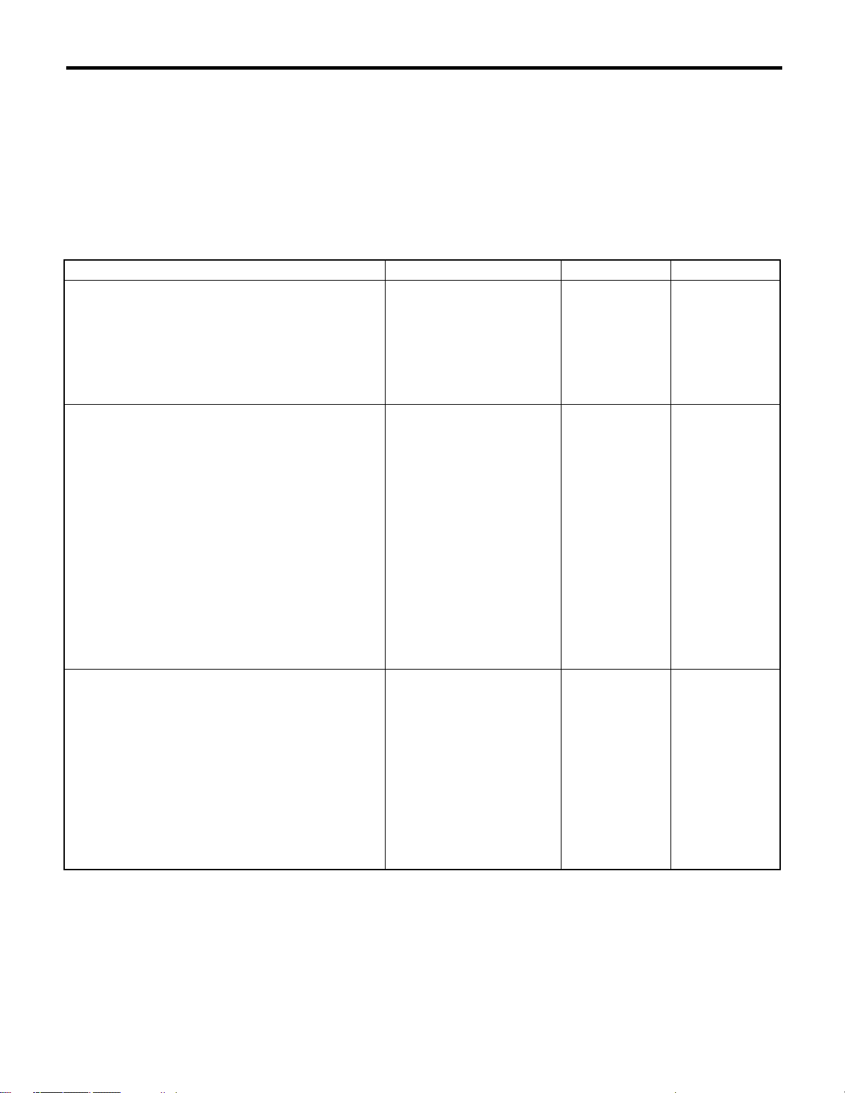
Step Check Yes No
1 CHECK PRE-INSPECTION.
1) Ask the customer when and how the trou-
ble occurred using interview checklist. <Ref. to
ABS(diag)-4, Check List for Interview.>
2) Before performing diagnostics, check the
component which might affect ABS problems.
<Ref. to ABS(diag)-8, INSPECTION, General
Description.>
Is the component that might
influence the ABS problem
normal?
Go to step 2. Repair or replace
each unit.
2 CHECK INDICATION OF DTC ON SCREEN.
1) Turn the ignition switch to OFF.
2) Connect the Subaru Select Monitor to data
link connector.
3) Turn the ignition switch to ON and Subaru
Select Monitor power switch to ON.
N
O
TE:
If the communication function of the Subaru Se-
lect Monitor cannot be executed normally,
check the communication circuit. <Ref. to
ABS(diag)-19, COMMUNICATION FOR INI-
TIALIZING IMPOSSIBLE, INSPECTION, Sub-
aru Select Monitor.>
4) Read the DTC. <Ref. to ABS(diag)-24,
OPERATION, Read Diagnostic Trouble Code
(DTC).>
5) Record all DTCs and Freeze Frame Data.
Is DTC displayed? Go to step 4. Go to step 3.
3 PERFORM THE GENERAL DIAGNOSTICS.
1) Inspect using “General Diagnostic Table”.
<Ref. to ABS(diag)-77, General Diagnostic
Table. >
2) Perform clear memory mode. <Ref. to
ABS(diag)-17, CLEAR MEMORY MODE,
OPERATION, Subaru Select Monitor.>
3) Perform the inspection mode. <Ref. to
ABS(diag)-25, Inspection Mode.>
4) Read the DTC. <Ref. to ABS(diag)-16,
READ DIAGNOSTIC TROUBLE CODE (DTC),
OPERATION, Subaru Select Monitor.>
Check the DTC does not displayed.
Does the ABS warning light go
off after turning the ignition
switch to ON?
Finish the diagno-
sis.
Check in accor-
dance with “Diag-
nostic Procedure
for ABS”.<Ref.to
ABS(diag)-21, NO
TROUBLE CODE,
INSPECTION,
Subaru Select
Monitor.>
ABS(diag)-3
ABS (DIAGNOSTICS)
Basic Diagnostic Procedure
4 PERFORM THE DIAGNOSIS.
1) Refer to the “List of Diagnostic Trouble
Code (DTC)”. <Ref. to ABS(diag)-34, LIST, List
of Diagnostic Trouble Code (DTC).>
2) Fix the wrong part.
3) Perform clear memory mode. <Ref. to
ABS(diag)-17, CLEAR MEMORY MODE,
OPERATION, Subaru Select Monitor.>
4) Perform the inspection mode. <Ref. to
ABS(diag)-25, Inspection Mode.>
5) Read the DTC. <Ref. to ABS(diag)-16,
READ DIAGNOSTIC TROUBLE CODE (DTC),
OPERATION, Subaru Select Monitor.>
Is DTC displayed? Repeat step 1 to 4
until DTC is not
shown.
Finish the diagno-
sis.
Step Check Yes No
ABS(diag)-4
ABS (DIAGNOSTICS)
Check List for Interview
2. Check List for Interview
A: CHECK
Check the following items about the vehicle’sstate.
1. STATE OF ABS WARNING LIGHT
ABS warning light
comes on.
❏Always
❏Sometimes
❏Only once
❏Not come on
•When / how long does it come on?
Ignition key position ❏LOCK
❏ACC
❏ON (before starting engine)
❏START
❏ON (after Engine starting, engine is running)
❏ON (after Engine starting, engine is at a standstill)
Timing ❏Immediately after turning the ignition to ON
❏Immediately after turning the ignition to START
❏When accelerating —km/h
—MPH
❏When driving at a constant speed km/h MPH
❏When decelerating —km/h
—MPH
❏When turning to the right Steering angle: deg
Steering time: Sec.
❏When turning to the left Steering angle: deg
Steering time: Sec.
❏When operating other electrical parts
•Parts name:
•Operating condition:
ABS(diag)-5
ABS (DIAGNOSTICS)
Check List for Interview
2. STATE OF BRAKE WARNING LIGHT
Brake warning light
comes on.
❏Always
❏Sometimes
❏Only once
❏Not come on
❏When pulling the parking brake lever up.
❏When releasing the parking brake lever down.
•When / how long does it come on?
Ignition key position ❏LOCK
❏ACC
❏ON (before starting engine)
❏START
❏ON (after Engine starting, engine is running)
❏ON (after Engine starting, engine is at a standstill)
Timing ❏Immediately after turning the ignition to ON
❏Immediately after turning the ignition to START
❏When accelerating —km/h
—MPH
❏When driving at a constant speed km/h MPH
❏When decelerating —km/h
—MPH
❏When turning to the right Steering angle: deg
Steering time: Sec.
❏When turning to the left Steering angle: deg
Steering time: Sec.
❏When operating other electrical parts
•Parts name:
•Operating condition:
ABS(diag)-6
ABS (DIAGNOSTICS)
Check List for Interview
3. SYMPTOMS
ABS operating condi-
tion
❏Does not move.
❏Operates only when applying an abrupt brake. Vehicle speed: km/h
MPH
•How to step on brake pedal:
a) Operating time: Sec.
b) Operating noise: ❏Occurs. / ❏Does not occur.
•What kind of noise? ❏Knocking
❏Gong gong
❏Bong
❏Buzz
❏Gong gong buzz
❏Others:
c) Reaction force of brake pedal
❏Stick
❏Weak pedal resistance
❏Strong pedal resistance
❏Others:
Behavior of vehicle a) Directional stability cannot be obtained or the steering refuses to work when applying brakes:
❏Ye s / ❏No
•When: ❏When turning to the right
❏When turning to the left
❏When spinning
❏Others:
b) Directional stability cannot be obtained or the steering refuses to work when accelerating:
❏Ye s / ❏No
•When: ❏When turning to the right
❏When turning to the left
❏When spinning
❏Others:
c) Poor brake performance: ❏Ye s / ❏No
•What kind: ❏Long braking/stopping distance
❏Brakes lock or drag
❏Long pedal stroke
❏Pedal sticks.
❏Others:
d) Poor acceleration: ❏Ye s / ❏No
•What kind: ❏Not accelerate
❏Engine stalls.
❏Others:
e) Occurrence of vibration: ❏Ye s / ❏No
•Where
•What kind:
f) Occurrence of noise: ❏Ye s / ❏No
•Where
•What kind:
g) Other troubles occurred: ❏Ye s / ❏No
•What kind:
ABS(diag)-7
ABS (DIAGNOSTICS)
Check List for Interview
4. CONDITIONS UNDER WHICH TROUBLE OCCURS
Environment a) Weather ❏Fine
❏Cloudy
❏Rainy
❏Snowy
❏Others:
b) Ambient temperature °C(°F)
c) Road ❏Inner city
❏Suburbs
❏Highway
❏Local street
❏Uphill
❏Downhill
❏Paved road
❏Gravel road
❏Muddy road
❏Sandy place
❏Others:
d) Road surface ❏Dried
❏Wet
❏Coveredwithfreshsnow
❏Covered with hardened snow
❏Frozen slope
❏Others:
Condition a) Brakes Deceleration: G
❏Intermittent / ❏Temporary
b) Accelerator Acceleration: G
❏Intermittent / ❏Temporary
c) Vehicle speed km/h MPH
❏Advancing
❏When accelerating
❏When decelerating
❏At low speed
❏When turning
❏Others:
d) Tire inflation pressure Front RH tire: kPa
Front LH tire: kPa
Rear RH tire: kPa
Rear LH tire: kPa
e) Degree of wear Front RH tire:
Front LH tire:
Rear RH tire:
Rear LH tire:
f) Genuine parts are used.: ❏Yes / ❏No
g) Tire chain is attached.: ❏Ye s / ❏No
h) T-type tire is used.: ❏Ye s / ❏No
i) Condition of suspension alignment:
j) Loading state:
k) Repair parts are used.: ❏Yes / ❏No
•Contents:
l) Others:
ABS(diag)-8
ABS (DIAGNOSTICS)
General Description
3. General Description
A: CAUTION
1. SUPPLEMENTAL RESTRAINT SYSTEM
“AIRBAG”
Airbag system wiring harness is routed near the
ABS wheel speed sensor and ABSCM&H/U.
CAUTION:
•Airbag system connectors are colored yel-
low. Do not use the electrical test equipment on
these circuits.
•Be careful not to damage the airbag system
wiring harness when servicing the ABS wheel
speed sensor and ABSCM&H/U.
B: INSPECTION
Before performing diagnosis, check the following
items which might affect ABS problems.
1. BATTERY
Measure battery voltage and check electrolyte.
Standard voltage: 12 V or more
Specific gravity: More than 1.260
2. GROUND
Check the ABS ground (B302) bolt, tightening
torque.
Tightening torque:
13 N
⋅
m (1.3 kgf-m, 9.4 ft-lb)
3. BRAKE FLUID
1) Check the brake fluid level.
2) Check the brake fluid for leaks.
4. HYDRAULIC UNIT
Check the hydraulic unit.
•With brake tester <Ref. to ABS-9, CHECKING
THE HYDRAULIC UNIT ABS OPERATION WITH
BRAKE TESTER, INSPECTION, ABS Control
Module and Hydraulic Control Unit (ABSCM&H/
U).>
•Without brake tester <Ref. to ABS-8, CHECK-
ING THE HYDRAULIC UNIT ABS OPERATION
BY PRESSURE GAUGE, INSPECTION, ABS
Control Module and Hydraulic Control Unit (AB-
SCM&H/U).>
5. BRAKE DRAG
Check for brake drag.
6. BRAKE PAD AND ROTOR
Check the brake pad and rotor.
•FRONT <Ref. to BR-19, INSPECTION, Front
Brake Pad.> <Ref. to BR-21, INSPECTION, Front
Disc Rotor.>
•REAR <Ref. to BR-30, INSPECTION, Rear
Brake Pad.> <Ref. to BR-32, INSPECTION, Rear
Disc Rotor.>
7. TIRE
Check the tire specifications, tire wear and air pres-
sure. <Ref. to WT-2, SPECIFICATION, General
Description.>
ABS(diag)-9
ABS (DIAGNOSTICS)
General Description
C: PREPARATION TOOL
1. SPECIAL TOOL
2. GENERAL PURPOSE TOOL
ILLUSTRATION TOOL NUMBER DESCRIPTION REMARKS
18482AA010
(Newly adopted tool)
CARTRIDGE Troubleshooting for electrical systems.
22771AA030 SUBARU SELECT
MONITOR KIT
Troubleshooting for electrical systems.
TOOL NAME REMARKS
Circuit tester Used for measuring resistance, voltage and amperage.
Oscilloscope Used for measuring sensor.
ST18482AA010
ST22771AA030
ABS(diag)-10
ABS (DIAGNOSTICS)
Electrical Component Location
4. Electrical Component Location
A: LOCATION
(1) ABS control module and hydraulic
control unit (ABSCM&H/U)
(5) Tone wheel (11) Brake and EBD warning light
(6) ABS wheel speed sensor (12) Driver’s control center differential
control module (STI model)
(2) Connector (7) Wheel cylinder
(3) ABS warning light (8) G sensor (13) Yaw rate & lateral G sensor (STI
model)
(4) Data link connector (for Subaru
Select Monitor)
(9) Stop light switch
(10) Master cylinder (14) Transmission control module (AT
model)
ABS00878
(7)
(5)
(3)
(11)
(4)
(2)
(1)
(6)
(5)
(7)
(6)
(5)
(7)
(10)
(9)
(14)
(8)
(6)
(6)
(5)
(7)
(13)
(12)
ABS(diag)-11
ABS (DIAGNOSTICS)
Electrical Component Location
ABS00563
(1)
ABS00798
(11)
(3)
ABS00658
(8)
(4) EN-01150
ABS00659
(5)
(6)
FRONT
(5)
(6)
ABS00660
REAR
ABS00651
(13)
ABS(diag)-12
ABS (DIAGNOSTICS)
Control Module I/O Signal
5. Control Module I/O Signal
A: ELECTRICAL SPECIFICATION
NOTE:
•Terminal numbers in ABSCM&H/U connector are as shown in the figure.
•ABS warning light is illuminates when the connector is removed from ABSCM&H/U.
(1) ABS control module and hydraulic
control unit (ABSCM&H/U) con-
nector
ABS00409
B301
7 8 9 10 116541
15141312 2 3
22 23 24 25 2621201916 17 18
(1)
ABS(diag)-13
ABS (DIAGNOSTICS)
Control Module I/O Signal
*1: Measure the I/O signal voltage after removing the connector from the ABSCM&H/U terminal.
Description
Te r mi nal
No.
(+) —(−)
Input/Output signal
Measured value and measuring conditions
ABS wheel speed sen-
sor
(Wheel speed sensor)
Front LH wheel Ground 16 —
Signal 1 —16 When the 20 Hz. 0.12 —1V
Front RH wheel Ground 5 —
Signal 6 —5 When the 20 Hz. 0.12 —1V
Rear LH wheel Ground 2 —
Signal 3 —2 When the 20 Hz. 0.12 —1V
Rear RH wheel Ground 4 —
Signal 19 —4 When the 20 Hz. 0.12 —1V
CAN communication line (+) 26 2.5 —1.5 V pulse signal
CAN communication line (−)113.5—2.5 V pulse signal
Valve relay power supply *1 14 —15 10 —15 V
Motor relay power supply *1 13 —15 10 —15 V
G sensor
Power supply 24 —10 4.75 —5.25 V
Ground 10 —
Output 21 —10 2.1 —2.5 V when the vehicle is on a level surface
Stop light switch *1 20 —15 Less than 1.5 V when the stop light is OFF; otherwise,
10 —15 V when the stop light is ON.
ABS warning light 22 —15
After turning the ignition switch to ON, 10 —15 V during
1.5 seconds and less than 1.5 V after 1.5 seconds
passed.
Brake warning light (EBD warning light) 8 —15
After turning the ignition switch to ON, 10 —15 V during
1.5 seconds and less than 1.5 V after 1.5 seconds
passed.
Subaru Select Monitor 7 —15 Less than 1.5 V when no data is received.
0←→ 12 V pulse (in communication)
Power supply *1 18 —15 WhentheignitionswitchisON,10—15 V.
Grounding line 12 —
Grounding line 15 —
ABS(diag)-14
ABS (DIAGNOSTICS)
Control Module I/O Signal
B: WIRING DIAGRAM
(1) Battery (12) Rear inlet solenoid valve LH (23) Front ABS wheel speed sensor
RH
(2) Ignition switch (13) Rear outlet solenoid valve LH
(3) ABS control module and hydraulic
control unit (ABSCM&H/U)
(14) Rear inlet solenoid valve RH (24) Rear ABS wheel speed sensor LH
(15) Rear outlet solenoid valve RH (25) Rear ABS wheel speed sensor RH
(4) ABS control module (16) Data link connector (26) Parking brake switch
(5) Valve relay (17) ABS warning light (27) Brake fluid level switch
(6) Motor relay (18) Brake warning light (28) Transmission control module (AT
model)
(7) Motor (19) Stop light switch
(8) Front inlet solenoid valve LH (20) Stop light (29) Driver’s control center differential
control module (STI model)
(9) Front outlet solenoid valve LH (21) G sensor
(10) Front inlet solenoid valve RH (22) Front ABS wheel speed sensor LH (30) Yaw rate & lateral G sensor (STI
model)
(11) Front outlet solenoid valve RH
ABS00882
(3)
(7)
(8)
M
(9)
(10)
(16)
(17)
(2)
(4)
(5)
(6)
(1)
(18)
(26)
(19)
(20)
(21)
(22)
(11)
(12)
(13)
(14)
(15)
(23)
(24)
(25)
(27)
(30) (29)
(28)
ABS(diag)-15
ABS (DIAGNOSTICS)
Control Module I/O Signal
C: WAVEFORM
(1) ABS wheel speed sensor
(2) Terminal No.
(3) Standard output voltage
ABS00034
[V]
(1)
(2)
(3)
910
78
0
20 Hz
1V
20 Hz : 0.12
1211
1514
ABS(diag)-16
ABS (DIAGNOSTICS)
Subaru Select Monitor
6. Subaru Select Monitor
A: OPERATION
1. READ DIAGNOSTIC TROUBLE CODE
(DTC)
1) Prepare the Subaru Select Monitor kit.
2) Connect the diagnosis cable to Subaru Select
Monitor.
3) Insert the cartridge into Subaru Select Monitor.
<Ref. to ABS(diag)-9, SPECIAL TOOL, PREPA-
RATION TOOL, General Description.>
4) Connect the Subaru Select Monitor to data link
connector.
(1) Data link connector located in the lower por-
tion of instrument panel (on the driver’sside).
(2) Connect the diagnosis cable to data link
connector.
CAUTION:
Do not connect the scan tools except for Suba-
ru Select Monitor and general scan tool.
5) Turn the ignition switch to ON (engine OFF) and
Subaru Select Monitor power switch to ON.
6) On the «Main Menu»display screen, select the
{Each System Check} and press [YES] key.
7) On the «System Selection Menu»display
screen, select the {Brake Control System} and
press [YES] key.
8) Press the [YES] key after the information of en-
gine type is displayed.
9) On the «ABS Diagnosis»display screen, select
the {DTC Display} and press [YES] key.
10) On the «DTC Display»display screen, select
the {Current DTC} or {History DTC} and press
[YES] key.
NOTE:
•For detailed operation procedure, refer to the
SUBARU SELECT MONITOR OPERATION MAN-
UAL.
•For detailed concerning the DTC, refer to the
LIST OF DTC. <Ref. to ABS(diag)-34, List of Diag-
nostic Trouble Code (DTC).>
•A maximum of 3 DTCs are displayed in order of
occurrence.
•If a particular DTC is not properly stored in mem-
ory (due to a drop in ABSCM&H/U power supply,
etc.) when a problem occurs, the DTC, followed by
a question mark “?”, appears on the Subaru Select
Monitor display. This shows it may be an unreliable
reading.
ABS00111
ABS00112
EN-01163
(1) Power switch
Display screen Contents to be monitored
Latest The most recent DTC appears on Sub-
aru Select Monitor display.
Old The second most recent DTC appears
on Subaru Select Monitor display.
Older The third most recent DTC appears on
Subaru Select Monitor display.
Reference DTC issued after elapse of a specified
period of time.
ABS00114
(1)
ABS(diag)-17
ABS (DIAGNOSTICS)
Subaru Select Monitor
2. READ CURRENT DATA
1) On the «Main Menu»display screen, select the {Each System Check} and press «YES»key.
2) On the «System Selection Menu»display screen, select the {Brake Control System} and press «YES»
key.
3) Press the «YES»key after the information of ABS type is displayed.
4) On the «Brake Control Diagnosis»display screen, select the {Current Data Display & Save} and press
«YES»key.
5) On the «Data Display Menu»display screen, select the {Data Display} and press «YES»key.
6) Using the scroll key, move the display screen up or down until desired data is shown.
•A list of the support data is shown in the following table.
NOTE:
For detailed operation procedure, refer to the “SUBARU SELECT MONITOR OPERATION MANUAL”.
3. CLEAR MEMORY MODE
1) On the «Main Menu»display screen, select the
{2. Each System Check} and press «YES»key.
2) On the «System Select Menu»display screen,
select the {Brake System} and press «YES»key.
3) Press the «YES»key after the information of en-
gine type is displayed.
4) On the «Brake Control Diagnosis»display
screen, select the {Clear Memory} and press
«YES»key.
5) When the “Done”and “turn ignition switch to
OFF”are shown on display screen, turn the Subaru
Select Monitor power switch and ignition switch to
OFF.
NOTE:
For detailed operation procedure, refer to the
“SUBARU SELECT MONITOR OPERATION
MANUAL”.
Display screen Contents to be monitored Unit of measure
FR Wheel Speed Wheel speed detected by Front ABS wheel speed sensor RH is
displayed km/h or MPH
FL Wheel Speed Wheel speed detected by Front ABS wheel speed sensor LH is
displayed km/h or MPH
RR Wheel Speed Wheel speed detected by Rear ABS wheel speed sensor RH is
displayed km/h or MPH
RL Wheel Speed Wheel speed detected by Rear ABS wheel speed sensor LH is dis-
played km/h or MPH
Stop Light Switch Stop light switch signal ON or OFF
G Sensor Output Signal Vehicle acceleration detected by analog G sensor is displayed. m/s (m/s2)
Lateral G Sensor Output Sig-
nal
Lateral G detected by Lateral G sensor is displayed in voltage. (STI
model) m/s (m/s2)
Valve Relay Signal Valve Relay Signal ON or OFF
ABS Warning Lamp ON operation of ABS warning light is displayed. ON or OFF
EBD Warning Light ON operation of EBD warning light is displayed. ON or OFF
Motor Relay Monitor Monitor voltage of motor relay is displayed. V
IG power supply voltage Voltage supplied to ABSCM&H/U is displayed. V
ABS Control Flag ABS control condition is displayed. ON or OFF
ABS OK B Signal ABS system normal/abnormal is displayed. ON or OFF
Display screen Contents to be monitored
Clear memory? Function of clearing DTC.
ABS(diag)-18
ABS (DIAGNOSTICS)
Subaru Select Monitor
4. ABS SEQUENCE CONTROL
5. FREEZE FRAME DATA
NOTE:
•Data stored at the time of trouble occurrence is
shown on display.
•Each time trouble occurs, the latest information
is stored in the freeze frame data in memory.
•Freeze frame data will be memorized maximum
to three.
•If freeze frame data is not properly stored in
memory (due to a drop in ABSCM power supply,
etc.), a DTC, preceded by a question mark “?”, ap-
pears on the Subaru Select Monitor display. This
shows it may be an unreliable reading.
Display
screen Contents to be monitored Index No.
ABS
sequence
control
Perform ABS sequence
control by operating valve
and pump motor sequen-
tially.
<Ref. to ABS-
10, ABS
Sequence Con-
trol.>
Display screen Contents to be monitored
FR wheel speed
Wheel speed detected by Front ABS
wheel speed sensor RH is displayed in
km/h or mile/h.
FL wheel speed
Wheel speed detected by Front ABS
wheel speed sensor LH is displayed in
km/h or mile/h.
RR wheel speed
Wheel speed detected by Rear ABS
wheel speed sensor RH is displayed in
km/h or mile/h.
RL wheel speed
Wheel speed detected by Rear ABS
wheel speed sensor LH is displayed in
km/h or mile/h.
IG power voltage
Power (in volts) supplied to ABSCM& H/
U appears on the Subaru Select Monitor
display.
G sensor output
voltage
Voltage equivalent to vehicle accelera-
tion detected by analog G sensor is dis-
played.
Lateral G sen-
sor output volt-
age
Voltage equivalent to Lateral G detected
by analog Lateral G sensor is displayed.
Motor relay mon-
itor Motor relay operation monitor signal
Stop light switch Stop light switch signal
ABS operation
signal ABS operation signal
Power Supply
Failure
Occurrence of abnormal voltage during
malfunction is displayed.
Vehicle speed Vehicle speed is displayed.
ABS(diag)-19
ABS (DIAGNOSTICS)
Subaru Select Monitor
B: INSPECTION
1. COMMUNICATION FOR INITIALIZING IMPOSSIBLE
DETECTING CONDITION:
Faulty harness connector
TROUBLE SYMPTOM:
Communication cannot be executed between ABS and Subaru select monitor.
WIRING DIAGRAM:
ABS00832
BATTERY
SBF-1SBF-4No.18
GENERATOR
B40
B301
E
E
1
10
DATA LINK
CONNECTOR
7
15
18
ABSCM & H/U
IGNITION
SWITCH
F44
B61
SBF-5
F46
B108
2
*1
: TURBO MODEL : 6
: EXCEPT TURBO MODEL : 2
*1
SHORT
CONNECTOR
1
4
B264
F46 B40
1
2
1
212345678
9
10 11 12 13 14 15 16
F44
1234
5 6 7 8
B301
456789
16 17 18 19 20
231
21 22 23 24 25 26
10 11
13 1412 15
B264
34
12
ABS(diag)-20
ABS (DIAGNOSTICS)
Subaru Select Monitor
Step Check Yes No
1 CHECK IGNITION SWITCH. Is the ignition switch turned to
ON?
Go to step 2. Tu r n t h e i g n i t i o n
switch to ON, and
select ABS mode
using Subaru
Select Monitor.
2 CHECK BATTERY.
1) Turn the ignition switch to OFF.
2) Measure the battery voltage.
Is the voltage more than 11 V? Go to step 3. Charge or replace
the battery.
3 CHECK BATTERY TERMINAL. Is there poor contact at battery
terminal?
Repair or tighten
the battery termi-
nal.
Go to step 4.
4 CHECK COMMUNICATION OF SUBARU SE-
LECT MONITOR.
1) Turn the ignition switch to ON.
2) Using the Subaru Select Monitor, check
whether communication to other system can
be executed normally.
Are the name and year of sys-
tem displayed on Subaru
Select Monitor?
Go to step 8. Go to step 5.
5 CHECK COMMUNICATION OF SUBARU SE-
LECT MONITOR.
1) Turn the ignition switch to OFF.
2) Disconnect the ABSCM&H/U connector.
3) Turn the ignition switch to ON.
4) Check whether communication to other
systems can be executed normally.
Are the name and year of sys-
tem displayed on Subaru
Select Monitor?
Replace the
ABSCM&H/U.
<Ref. to ABS-6,
ABS Control Mod-
ule and Hydraulic
Control Unit
(ABSCM&H/U).>
Go to step 6.
6 CHECK HARNESS CONNECTOR BETWEEN
EACH CONTROL MODULE AND DATA LINK
CONNECTOR.
1) Turn the ignition switch to OFF.
2) Disconnect the ABSCM&H/U, ECM and
TCM connectors.
3) Measure the resistance between data link
connector and chassis ground.
Connector & terminal
(B40) No. 10 —Chassis ground:
Is the resistance more than 1
MΩ?
Go to step 7. Repair the har-
ness and connec-
tor between each
control module
and data link con-
nector.
7 CHECK OUTPUT SIGNAL FOR ABSCM& H/
U.
1) Turn the ignition switch to ON.
2) Measure the voltage between ABSCM&H/
U and chassis ground.
Connector & terminal
(B40) No. 10 (+) —Chassis ground (
−
):
Is the voltage less than 1 V? Go to step 8. Repair the har-
ness and connec-
tor between each
control module
and data link con-
nector.
8 CHECK HARNESS/CONNECTOR BETWEEN
ABSCM&H/U AND DATA LINK CONNEC-
TOR.
Measure the resistance between ABSCM&H/U
connector and data link connector.
Connector & terminal
(B301) No. 7 —(B40) No. 10:
Is the resistance less than 0.5
Ω?
Go to step 9. Repair the har-
ness and connec-
tor between
ABSCM&H/U and
data link connec-
tor.
9 CHECK INSTALLATION OF ABSCM&H/U
CONNECTOR.
TurntheignitionswitchtoOFF.
Is the ABSCM&H/U connector
inserted into ABSCM&H/U until
theclamplocksontoit?
Go to step 10. Insert the
ABSCM&H/U con-
nector into
ABSCM&H/U.

Other manuals for 2006 Impreza

1

Other Subaru Automobile manuals

Subaru 2003 Legacy User manual

Subaru

Subaru 2003 Legacy User manual

Subaru 2001 Forester User manual

Subaru

Subaru 2001 Forester User manual

Subaru 2002 Impreza User manual

Subaru

Subaru 2002 Impreza User manual

Subaru LEGACY User manual

Subaru

Subaru LEGACY User manual

Subaru Tribeca User manual

Subaru

Subaru Tribeca User manual

Subaru Legacy 2015 User manual

Subaru

Subaru Legacy 2015 User manual

Subaru 2004 LEGACY User manual

Subaru

Subaru 2004 LEGACY User manual

Subaru 2004 LEGACY User manual

Subaru

Subaru 2004 LEGACY User manual

Subaru 2007 Legacy Reference manual

Subaru

Subaru 2007 Legacy Reference manual

Subaru WRX-STI User manual

Subaru

Subaru WRX-STI User manual

Subaru Impreza User manual

Subaru

Subaru Impreza User manual

Subaru Forester 2020 User manual

Subaru

Subaru Forester 2020 User manual

Subaru 2001 Forester User manual

Subaru

Subaru 2001 Forester User manual

Subaru Impreza 2004 User manual

Subaru

Subaru Impreza 2004 User manual

Subaru Outback User manual

Subaru

Subaru Outback User manual

Subaru Tribeca User manual

Subaru

Subaru Tribeca User manual

Subaru 2012 Forester User manual

Subaru

Subaru 2012 Forester User manual

Subaru 2005 Legacy User manual

Subaru

Subaru 2005 Legacy User manual

Subaru 2016 Outback User manual

Subaru

Subaru 2016 Outback User manual

Subaru BRZ 2021 User manual

Subaru

Subaru BRZ 2021 User manual

Subaru Tribeca User manual

Subaru

Subaru Tribeca User manual

Subaru 2003 Legacy User manual

Subaru

Subaru 2003 Legacy User manual

Subaru Impreza Installation guide

Subaru

Subaru Impreza Installation guide

Subaru 2001 LEGACY User manual

Subaru

Subaru 2001 LEGACY User manual

Popular Automobile manuals by other brands

RAM 2014 RAM PROMASTER Supplement

RAM

RAM 2014 RAM PROMASTER Supplement

Toyota 2003 COROLLA owner's manual

Toyota

Toyota 2003 COROLLA owner's manual

Mercedes-Benz E-Class 2023 manual

Mercedes-Benz

Mercedes-Benz E-Class 2023 manual

Jeep GRAND CHEROKEE SRT 2016 owner's manual

Jeep

Jeep GRAND CHEROKEE SRT 2016 owner's manual

Volvo S80 - overview

Volvo

Volvo S80 - overview

Chevrolet 2003 Corvette owner's manual

Chevrolet

Chevrolet 2003 Corvette owner's manual

Mercedes-Benz 2003 C 240 4MATIC Operator's manual

Mercedes-Benz

Mercedes-Benz 2003 C 240 4MATIC Operator's manual

Volvo V40 owner's manual

Volvo

Volvo V40 owner's manual

Volvo V70 SPORT owner's manual

Volvo

Volvo V70 SPORT owner's manual

Mercedes-Benz Metris Service booklet

Mercedes-Benz

Mercedes-Benz Metris Service booklet

CRAWLER OTAG385 user guide

CRAWLER

CRAWLER OTAG385 user guide

Mercedes-Benz GLC 200 4MATIC owner's manual

Mercedes-Benz

Mercedes-Benz GLC 200 4MATIC owner's manual

Mazda 2007 CX-9 owner's manual

Mazda

Mazda 2007 CX-9 owner's manual

Pontiac 2009 Torrent owner's manual

Pontiac

Pontiac 2009 Torrent owner's manual

Fiat 500L Owner's handbook

Fiat

Fiat 500L Owner's handbook

Chevrolet 2006 Equinox owner's manual

Chevrolet

Chevrolet 2006 Equinox owner's manual

Jeep AVENGER 2023 Owner's handbook

Jeep

Jeep AVENGER 2023 Owner's handbook

Volvo V50 user manual

Volvo

Volvo V50 user manual

manuals.online logo
manuals.online logoBrands
  • About & Mission
  • Contact us
  • Privacy Policy
  • Terms and Conditions

Copyright 2025 Manuals.Online. All Rights Reserved.