Subzero Wolf OG Series User manual

Page 2
Outdoor Grill (OG) Series
Installation Information
2-2
#814144 - Revision B - October, 2011
GENERAL INSTALLATION INFORMATION
This section of the manual covers some of the installa-
tion issues that a service technician may need to know
when servicing a Wolf Outdoor Grill. If additional instal-
lation information is needed after reviewing this section
of the manual, refer to the complete Installation Guide
or contact Wolf Appliance Customer Service.
Regulations
The installation of a Wolf OG appliance must conform
with local codes or, in the absence of local codes, either
the National Fuel Gas Code, ANZIZ223.1/NFPA54, or
CAN/CGA-B149.1, Natural Gas Installation Code or
CAN/CGA-B149.2, Propane Installation Code.
The utilization of an external electrical source requires
that when installed, a Wolf OG outdoor cooking gas
appliance must be electrically grounded in accordance
with the local codes or, in the absence of local codes,
with the National Electrical Code, ANSI/NFPA70, or the
Canadian Electrical Code, CSAC22.1. Keep any elec-
trical supply cord, or the rotisserie motor cord and the
gas supply hose away from any heated surfaces.
A Wolf OG appliance must be installed in accordance
with National Electrical Codes, as well as all state,
municipal and local codes. The correct voltage, fre-
quency and amperage must be supplied to the appli-
ance from a dedicated, grounded circuit which is pro-
tected by a properly sized circuit breaker or time delay
fuse. The proper voltage, frequency, and amperage rat-
ings are listed on the product rating plate.
Important Instructions to the Owner
• Installation and service must be performed by a
qualified installer, service agency or the gas supplier.
• Warranty service must be performed by a Wolf
authorized service center.
• Do not store or use gasoline or other flammable liq-
uids or vapors in the vicinity of this or any other
appliance. An LP gas cylinder not connected for use
shall not be stored in the vicinity of this or any other
appliance.
• In Massachusetts: All gas products must be installed
using a “Massachusetts” licensed plumber or gasfit-
ter. A “T” handle type manual gas valve must be
installed in the gas supply line to this appliance. This
applies to permanently installed natural gas and
propane installations. This does not apply to propane
portable installations using a 20-lb tank.
LOCATING THE GRILL
NOTE:A Wolf OG appliance is designed and certified
for outdoor use only. A Wolf OG appliance should
never be operated inside a building, garage, recreation
vehicle or any enclosed area.
When choosing an area for a grill, whether a portable or
built-in application, the following should be considered:
•Exposure to wind - a grill should be kept away from
windy areas but in a well ventilated area. The flow
of combustion and ventilation air around the grill can
not be obstructed.
•Proximity to traffic paths - a grill should be kept
clear of traffic paths.
•Length of gas supply line - The gas supply line
should be kept as short as possible to reduce pres-
sure drop.
•Levelness of application - The grill must be level
and flat. The supporting deck and countertop should
also be level and flat.
DO NOT LOCATE GRILL UNDER OVERHEAD COM-
BUSTIBLE SURFACES!
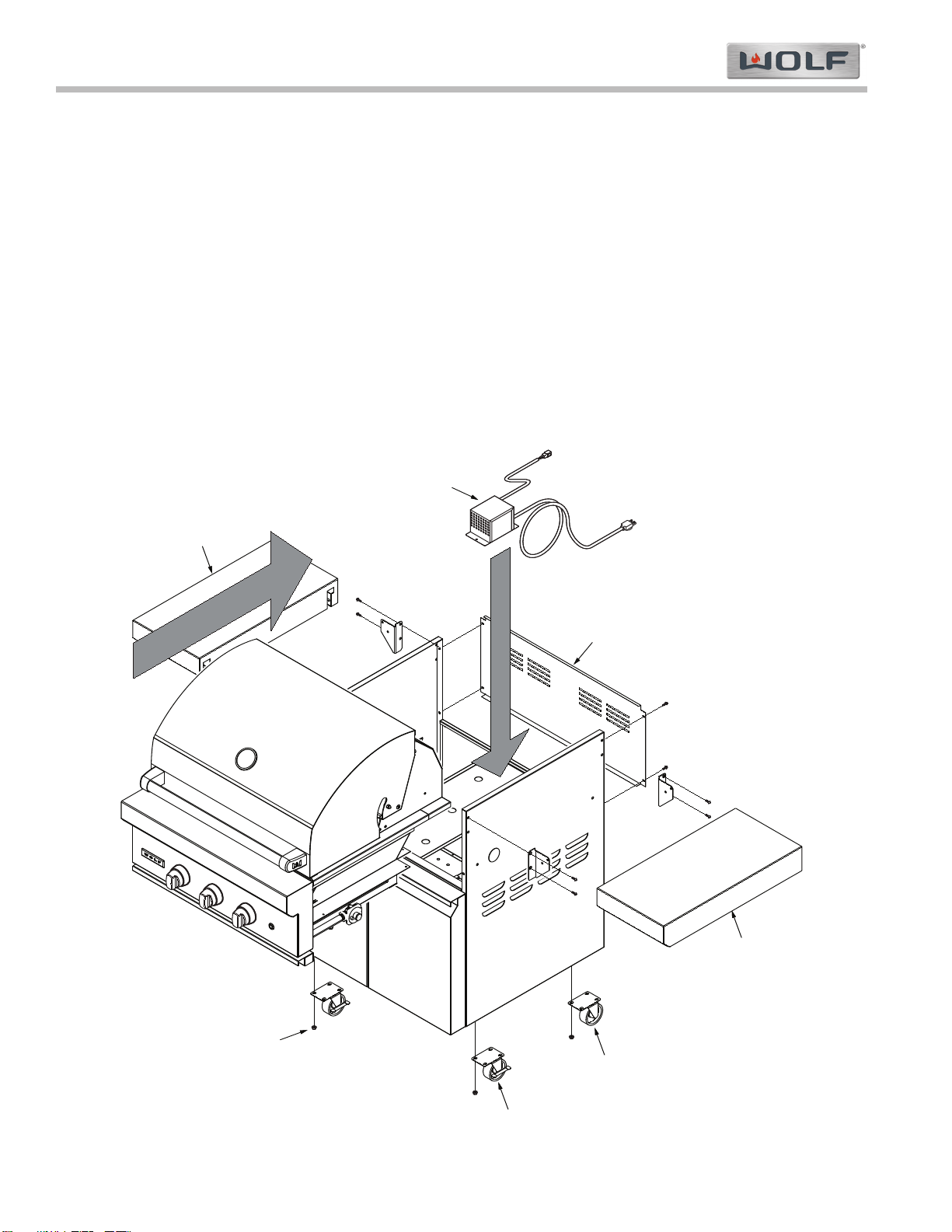
Portable Applications
•Wolf portable grill carts are available to fit most Wolf
outdoor grill models.
• Grill carts are sales accessories, sold separately
from the OG. appliance.
• There is no grill cart available for the OG54 model.

Page 3
Installation Information
Outdoor Grill (OG) Series
2-3 #814144 - Revision B - October, 2011
OG and OG Cart Overall Dimensions
OVERALL WIDTH
MAX DOOR/DRAWER CLEARANCE 22" (559)
24"
(610)
TO GRILL
PLATFORM
36
1
/
2
"
(927)
OVERALL
HEIGHT
27
3
/
4
"
(705)
12"
(305)
3"
(76)
30"
(762)
OVERALL DEPTH
12
1
/
2
"
(318)
TO GRILLING
SURFACE
27"
(686)
OVERALL
HEIGHT
OVERALL WIDTH
27
3
/
4
"
(705)
2
1
/
2
"
(64)
CLEARANCE
FOR OPEN
HOOD
OUTDOOR GRILL
(Model OG36 shown)
GRILL CART
(Model CART36 shown)
Outdoor Grill Models Overall Width
OG30 30” (762)
OG36 36” (914)
0G42 42" (1067)
0G54 54" (1067)
Outdoor Grill Cart Models Overall Width
CART30 30” (762)
CART36 36” (914)
CART42 42" (1067)
NOTE: Throughout this manual, dimensions in parentheses are in millimeters unless otherwise specified.
Figure 2-1. Grill & Cart Dimensions (See Tables Below for Width Dimensions)

Page 4
Outdoor Grill (OG) Series
Installation Information
2-4
#814144 - Revision B - October, 2011
Figure 2-2. Grill on Cart Installation
Locking Casters at front
Four (4) Nuts per caster
Back panel
Side Shelf
Transformer
Side Shelf
Non-locking Casters at rear
Grill Installation
Install OG Grill on Cart
There is a Wolf portable grill cart available to fit almost all Wolf outdoor grill models. To install a grill on a cart:
1. Attach casters to bottom corners of cart (locking casters go in front) using the nuts supplied with the casters
(See Figure 2-2).
2. Remove back panel, then install transformer on floor of cart, toward rear of cart, using the two mounting screws
(provided in cart body) (See Figure 2-2).
3. Extract screws from front inside flange of cart. They will be used later to affix grille to cart.
4. Place grill onto cart, but leave enough room at the back to make connection to transformer at right rear of cart.
Then, after connection to the transformer is made, slide grill back until it is fully engaged on the cart.
5. With grill in position, secure grill to cart with four screws provided. Mounting holes in the upper back corners of
the grill will align with holes in the cart. Secure with two screws. Remove the drip tray. Install two screws that
were removed in step 4 through side mounting holes below the grill front panel and into the cart.
6. Reattach back panel (See Figure 2-2).
7. Attach side shelves to cart (See Figure 2-1 below and Figure 2-2 / Side Shelf Installation, on next page). The
instructions on the next page are also supplied with the side shelves.
NOTE: If a Side Burner (SB13) will be installed on the grille cart, do not install the right side shelf. Side burner
installation is explained later in this section.

Page 5
Installation Information
Outdoor Grill (OG) Series
2-5 #814144 - Revision B - October, 2011
Figure 2-3. Side Shelf Installation Instructions

Page 6
Outdoor Grill (OG) Series
Installation Information
2-6
#814144 - Revision B - October, 2011
Built-In Applications
Wolf outdoor grills are designed for easy placement into a built-in enclosure.
• The enclosure for an OG model should be built according to specifications as described on the next page.
• Provisions must be made for the electrical supply and gas line connection.
• Specified clearances must be maintained.
• All installations require a deck to support the grill. The supporting deck should be level and flat and able to sup-
port 300 lbs (136 kg) for an OG installation.
• It is recommended that ventilation holes be provided in the enclosure so that gas will not become trapped in the
event of a leak.
Minimum Clearances
• A minimum clearance of 12” (305) from the sides and 12” (305) from the back of the grill to adjacent vertical com-
bustible construction must be maintained.
• A minimum clearance of 2-1/2” (64) from the back of the grill above cooking surface to non-combustible construc-
tion is required.
• A minimum of 6” (152) clearance to the sides of the grill above cooking surface to non-combustible construction is
recommended to provide space for the rotisserie motor and the spit rod. The grill can be installed directly next to
non-combustible construction below the cooking surface.
Insulating Liner
If the grill is to be placed into combustible enclosure, an approved insulating liner is necessary to prevent fire, prop-
erty damage and bodily injury. Use only the Wolf insulating liner. See Figure 2-4 below and refer to the illustration
on the next page for an OG model.
figure 2-4. Insulating Liner (36” Shown)

Page 7
Installation Information
Outdoor Grill (OG) Series
2-7 #814144 - Revision B - October, 2011
OG Built-in Installation Dimensions
36"
(914)
OPENING WIDTH
TOP VIEW
FRONT VIEW
11
3
/
4
"
(298)
OPENING
HEIGHT
6"
(152) min
TO
NON-COMBUSTIBLE
SIDE SURFACES
6"
(152) min
TO
NON-COMBUSTIBLE
SIDE SURFACES
OPENING WIDTH
FOR ACCESS DOORS OR
STORAGE DRAWERS
OPENING
HEIGHT
1"
(25) min
24
1
/
4
"
(616)
OPENING
DEPTH
2
1
/
2
"
(64) min
TO
NON-COMBUSTIBLE REAR SURFACES
COUNTERTOP
OVERHANG
OPENING
FOR GRILL
3
/
4
"
(19)
GAS SUPPLY
GAS SUPPLY
36"
(914)
OPENING WIDTH
TOP VIEW
FRONT VIEW
12
5
/
8
"
(321)
OPENING
HEIGHT
GAS SUPPLY
OPTIONAL
GAS SUPPLY
LOCATIONS
OPENING WIDTH
FOR ACCESS DOORS OR
STORAGE DRAWERS
26"
(660)
OPENING
DEPTH
OPENING
HEIGHT
12"
(305) min
TO
COMBUSTIBLE REAR SURFACES
12"
(305) min
TO
COMBUSTIBLE
SIDE SURFACES
12"
(305) min
TO
COMBUSTIBLE
SIDE SURFACES
1"
(25) min
COUNTERTOP
OVERHANG
OPENING
FOR LINER
3
/
4
"
(19)
NON-COMBUSTIBLE ENCLOSURE COMBUSTIBLE ENCLOSURE
(With Insulating Liner)
NON-COMBUSTIBLE ENCLOSURE
Outdoor Grill Models Opening Width
OG30 28-1/2" (724)
OG36 34-1/2" (876)
0G42 40-1/2" (1029)
OG54 52-1/2” (1334)
NOTE: Throughout this manual, dimensions in parentheses are in millimeters unless otherwise specified.
COMBUSTIBLE ENCLOSURE
Outdoor Grill Models Opening Width
OG30 33-1/2" (851)
OG36 39-1/2" (1003)
0G42 45-1/2" (1156)
OG54 57-1/2” (1461)
OPTIONAL DOOR OPENING
Access Doors Opening Width Opening Height
18" (457) Single 16-1/4" (413) 19" (483)
30" (762) Double 28-1/4" (718) 19" (483)
36" (914) Double 34-1/4" (870) 19" (483)
42" (1067) Double 40-1/4" (1022) 19" (483)
OPTIONAL DRAWER OPENING
Access Doors Opening Width Opening Height
30" (762) Single 27-1/4" (692) 9-3/4" (248)
13" (330) Double 12-1/8" (308) 19" (483)
13" (330) Triple 12-1/8" (308) 19" (483)
30" (762) Dbl w/Door 29-1/4" (743) 19" (483)

Page 8
Outdoor Grill (OG) Series
Installation Information
2-8
#814144 - Revision B - October, 2011
Burner Module Overall Dimensions
10
3
/
4
"
(273)
OVERALL
HEIGHT
13"
(330)
OVERALL
WIDTH
30"
(762)
OVERALL DEPTH
27
3
/
4
"
(705)
Side Burner (SB13) and Burner Module (BM13)
7"
(178)
G
3"
(76)
8"
(203)
G
36"
(914)
12"
(305)
OPENING
WIDTH
10"
(254)
OPENING
HEIGHT
6"
(152) min
TO
NON-COMBUSTIBLE
SIDE SURFACES
6"
(152) min
TO
NON-COMBUSTIBLE
SIDE SURFACES
24
1
/
4
"
(616)
OPENING
DEPTH
COUNTERTOP
OVERHANG
OPENING
FOR
MODULE
9
/
16
"
(14)
TOP VIEW
2
1
/
2
"
(64) min
TO NON-COMBUSTIBLE
REAR SURFACES
Burner Module (BM13) Built-in Installation Dimensions (Non-Combustible or Combustible Enclosure)

Page 9
Installation Information
Outdoor Grill (OG) Series
2-9 #814144 - Revision B - October, 2011
ELECTRICAL REQUIREMENTS
Install the Power Transformer
Wolf outdoor grills have a power transformer for the
lights and igniters which is concealed in a stainless
steel box with an attached power supply cord.
Cart Application - Two mounting screws are provided
for mounting the transformer inside, on the floor of the
cart.
Built-in Application - Secure the transformer box in a
dry location, away from the grill firebox and excessive
heat area, but within 2' (.6 m) of the right rear grill open-
ing.
NOTE: Do not install the transformer box inside the
insulating liner. The transformer box must be secured
away from excessive heat and in a dry location.
Make the transformer connections to the wire harness
located at the right rear of the grill to the harness of the
transformer box.
Plug the power cord from the transformer into a proper-
ly grounded GFCI 120 V AC outlet. The outlet must be
located within 6' (1.8 m) of the transformer.
Rotisserie Motor
The rotisserie motor requires a GFCI 120 V AC electri-
cal supply. The 9' (2.7 m) power cord on the motor is
equipped with a 3-prong grounded plug for protection
against shock hazard.
SHOCK HAZARD!
• THE POWER TRANSFORMER AND THE ROTIS-
SERIE MOTOR SUPPLIED WITH OUTDOOR GAS
GRILLS ARE EQUIPPED WITH 3-PRONG
GROUNDING PLUGS FOR PROTECTION
AGAINST SHOCK HAZARD. THE 3-PRONG
GROUNDING PLUGS SHOULD BE PLUGGED
DIRECTLY INTO PROPERLY GROUNDED 3-
PRONG OUTLETS. DO NOT CUT OR REMOVE A
GROUNDING PRONG FROM A PLUG.
• DO NOT USE AN EXTENSION CORD OR TWO-
PRONG ADAPTER.
GAS SAFETY REQUIREMENTS
NOTE:The outdoor gas grill must be connected to a
regulated gas supply by a qualified technician and in
accordance with local codes and ordinances.
Each appliance is set and tested at the factory for the
type of gas supply to be used. Identify the type of gas,
either natural gas or LP gas, and make sure that the
type of gas specified on the product rating plate match-
es the gas being supplied to the grill.
Conversion kits are available for both LP and natural
gas grills. Contact a Wolf dealer or distributor for more
information.
GAS SUPPLY REQUIREMENTS
Connect the grill to the gas supply line. The gas supply
line must be of adequate size to properly service all gas
appliances. Wolf recommends the use of a minimum
1/2" (13) I.D. commercial type flex hose from the gas
supply line to the grill connection. The units will operate
on 1/2" (13) pipe to a maximum run of 30' (9 m). All
plumbing to the flex hose must be 3/4" (19) minimum
I.D. pipe.
NOTE: For complete gas shutdown, an external gas
shut-off valve must be located near the appliance in an
accessible location (See Figure 2-5).
OPEN POSITION
TO APPLIANCE
GAS SUPPLY
LINE
Figure 2-5. External Gas Shut-off Valve
ENSURE THAT THE GAS SUPPLY HOSE DOES
NOT COME IN CONTACT WITH ANY HOT SURFACE
OF THE GRILL!

Page 10
Figure 2-7. Natural Gas Regulator
Outdoor Grill (OG) Series
Installation Information
2-10
#814144 - Revision B - October, 2011
NATURAL GAS INSTALLATIONS
The natural gas pressure regulator provided with natu-
ral gas grills is set for 4" (10 mb) WC (water column)
and is for use with natural gas only.
Natural Gas Safety Requirements
The gas appliance and its individual shut-off valve must
be disconnected from the gas supply piping system dur-
ing any pressure testing of that system at test pres-
sures greater than .5 psi (3.5 kPa).
The gas appliance must be isolated from the gas supply
piping system by closing its individual manual shut-off
valve during any pressure testing of the gas supply pip-
ing system at test pressures equal to or less than .5 psi
(3.5 kPa).
Natural Gas Connection
A typical natural gas installation is shown in Figures 2-6
and 2-7 below. Make sure that the pressure regulator
supplied with the grill is used and installed with the
arrow on the regulator pointing towards the grill. Do
not use a replacement regulator other than that speci-
fied by Wolf. Use only gas piping that is approved for
use with natural and LP gases.
REGULATOR REAR GAS
CONNECTION
BOTTOM GAS
CONNECTION
SHUT-OFF
VALVE
Figure 2-6. Natural Gas Connection
ADAPTER
CLOSE NIPPLE
TO GRILL
FROM GAS
SUPPLY
VENT
REGULATOR
LP GAS INSTALLATIONS
The LP gas pressure regulator provided with LP gas
grills is set for 10" (25 mb) WC (water column) and is
for use with LP gas only. The regulator comes connect-
ed to a hose for use with a 20-lb LP gas cylinder.
LP Gas Safety Requirements
The LP gas cylinder must be provided with an approved
over-filling preventive device (OPD) and a cylinder con-
nection device compatible with the connection for out-
door cooking appliances.
Any LP gas cylinder used with a Wolf appliance must
be constructed and marked in accordance with the
specifications for LP gas cylinders of the U.S.
Department of Transportation (D.O.T.) or the National
Standards of Canada CAN/CSA-B339, Cylinders,
Spheres and Tubes for the Transportation of Dangerous
Goods, and Commission, as applicable.
The LP gas cylinder must be provided with a shut-off
valve terminating in the cylinder valve outlet, and it
must include a collar to protect the cylinder valve.
NOTE: Do not operate the gas grill indoors or in any
enclosed area. If the gas grill is not in use, the gas
must be turned off at the LP gas cylinder. If the grill is
to be stored indoors, disconnect the cylinder and leave
it outdoors.

Page 11
Installation Information
Outdoor Grill (OG) Series
2-11 #814144 - Revision B - October, 2011
LP Gas Installation (Portable LP Connection)
One of the features of a Wolf OG grill cart is the pull-out
shelf for easy access to the LP gas cylinder. It is
designed to hold a 20-lb (5 gallon capacity) LP gas
cylinder.
To install the LP gas cylinder on a Wolf OG grill cart
(See Figure 2-8):
1. Open the door and pull the shelf out, then place the
cylinder on it.
2. Check to ensure that the gas valve on top of the
cylinder is closed.
3. Connect the LP gas regulator to the cylinder and
hand-tighten only. Open the cylinder valve and
check for leaks.
4. Tighten the thumb screw to secure the cylinder to
the shelf.
ALWAYS CHECK FOR GAS LEAKS AFTER CHANG-
ING A LP GAS CYLINDER!
Figure 2-8. Grill Cart Pull-out Shelf
LP Gas Connection
Install the pressure regulator and hose assembly sup-
plied with the grill as shown in Figures 2-9 and 2-10
below. Connect the 3/8" flare end of the hose to the
grill coupling using a 3/4" open wrench. Do not apply
pipe sealant to the 3/8" flare connection. Connect the
regulator to the LP cylinder and hand-tighten, do not
use a wrench.
GRILL COUPLING REGULATOR
HOSE ASSEMBLY
LP GAS
CYLINDER
VENT
VENT
Figure 2-9. LP Gas Connection
LP GAS
CYLINDER
TO GRILL
VENT
REGULATOR
COUPLING NUT
Figure 2-10. LP Gas Regulator
THE LP PRESSURE REGULATOR AND HOSE SUP-
PLIED WITH THE GRILL MUST USED WITH OUT
ALTERATION!
DO NOT PLACE MORE THAN ONE LP GAS CYLIN-
DER IN AN ENCLOSURE AT ONE TIME!

Page 12
Outdoor Grill (OG) Series
Installation Information
2-12
#814144 - Revision B - October, 2011
GAS LEAK TESTING
NOTE:Never use the outdoor grill without first testing
the gas line connections for gas leaks.
Perform a gas leak test each time the LP gas cylinder is
connected to the regulator and any time part of the gas
system is disconnected or replaced. This applies to
natural gas as well as LP gas. Perform a leak test at
least once each year whether the LP gas cylinder has
been disconnected or not.
NOTE:To prevent fire or explosion hazard, do not
smoke or permit sources of ignition in the area while
performing a leak test. Perform the gas leak test out-
doors in a well ventilated area.
Have a dealer check the LP gas cylinder for deteriora-
tion when the tank is filled in accordance with regula-
tions. Immediately replace the cylinder if any deteriora-
tion is found.
DO NOT USE AN OPEN FLAME TO CHECK FOR
GAS LEAKS. USE OF AN OPEN FLAME COULD
RESULT IN A FIRE, EXPLOSION AND BODILY
HARM.
Gas Leak Testing Procedure
1. Prepare a leak testing solution of soapy water by
combining a mixture of half liquid soap and half
water in a spray bottle.
2. Verify that all control knobs are in the OFF position.
3. Turn the cylinder valve knob counterclockwise one
turn to open.
4. Apply the leak testing solution by spraying on the
pipe joints, fittings and hose. Bubbles in the soap
and water solution indicate that a gas leak is pres-
ent.
5. Stop the leak by tightening the loose joint or by
replacing the faulty part with a replacement part
recommended by the Wolf. Do not attempt to
repair the cylinder valve if it should become dam-
aged. The cylinder must be replaced.
6. If you are unable to stop the leak, shut off the gas
supply at the cylinder valve. Remove the LP gas
cylinder. Call a Wolf authorized service center.
NOTE:Do not use the grill until the leak has been fixed.
7. Push in and turn any control knob to the ON posi-
tion to release pressure in the hose and manifold.
8. Turn the control knob to the OFF position.
OUTDOOR GRILL ASSEMBLY
Except for some minor parts, Wolf outdoor grills are
produced fully assembled and tested in the factory and
require no major assembly in the field. For the purpose
of safe shipping and transit, some parts such as the bri-
quette trays, warming rack and rotisserie components
are wrapped inside the grill and require minor assembly.
Remove all packaging materials, labels and protective
plastic film from the grill.
NOTE:Do not leave the grill or grill cart in the sun with
the protective plastic film on for an extended period or it
may be difficult to remove.
Verify that all grill components are included:
• Control knobs
• Hex-grates
• Large and small briquette tray assemblies
• Rotisserie motor with bracket
• Spit rod and meat forks
• Natural gas or LP gas regulator
• Basting pan
• Warming rack
• smoker box assembly
Installing Briquette Trays
1. Place the briquette trays into the grill above the
burners with the flash tube at the front (See Figure
2-11).
2. Place the hex-grates directly above the briquette
trays and make sure the square openings on the
hex-grates are at the front.
FLASH TUBE
Figure 2-11. Flash Tube Position
This manual suits for next models
4
Table of contents
Popular Grill manuals by other brands

Brinkmann
Brinkmann Stainless Steel 4 Burner Gas Grill owner's manual

Omcan
Omcan CE-IT-0291 instruction manual

Argos
Argos 287/6847 Assembly instructions

Carlo Cracco
Carlo Cracco MasterPRO BGMP-9099 instruction manual

Bull BBQ
Bull BBQ BULL-411U owner's manual

Delta Heat
Delta Heat DHBQ26G Installation, use & care manual