4
SUGATSUNE KOGYO CO.,LTD
Tokyo, JAPAN
SUGATSUNE KOGYO (UK) LTD
Reading, UK
Phone: +44 118 9272 955
SUGATSUNE EUROPE GmbH
Dusseldorf, GERMANY
Phone: +49 211 53812900
SUGATSUNE SHANGHAI Co., LTD
Shanghai, CHINA
Guangzhou, CHINA
SUGATSUNE KOGYO INDIA PRIVATE LIMITED
Mumbai, INDIA
SUGATSUNE AMERICA, INC
California, USA
Chicago, USA
Phone: +1 312 461 1081
SUGATSUNE CANADA, INC.
Phone: +1 514 312 5267
2019.08 0758-4
How to Remove Door
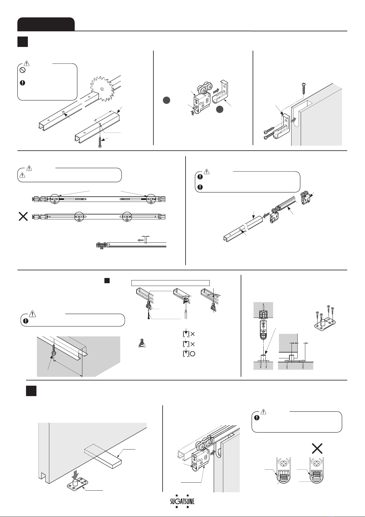
【1】Use a 10 mm support under the door.
【2】Pull out the upper roller main unit from the
door while raising the lever.
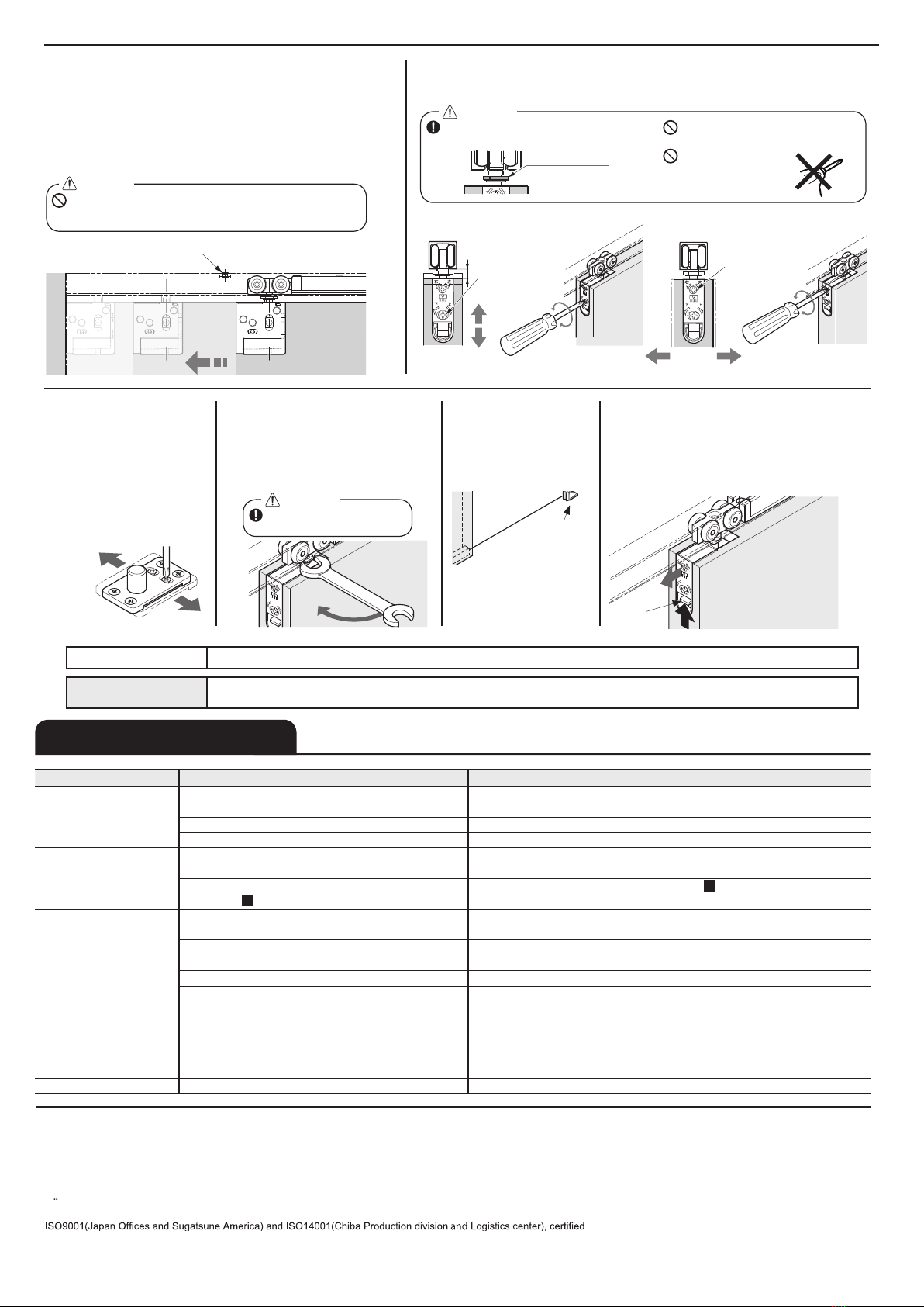
6. Fastening the Jump Prevention Nut
The jump prevention nut is on the
hanger bolt of the upper roller.
Tighten the nut with the optional
spanner⑪or 12 mm spanner until it
contacts the soft closer.
5.
Adjusting Floor Guide:
Adjustment Range 4 mm.
Slowly close and open
the door. If the door does
not move smoothly, it is
necessary to make an
DGMXVWPHQWWRWKHÀRRUJXLGH
and door.
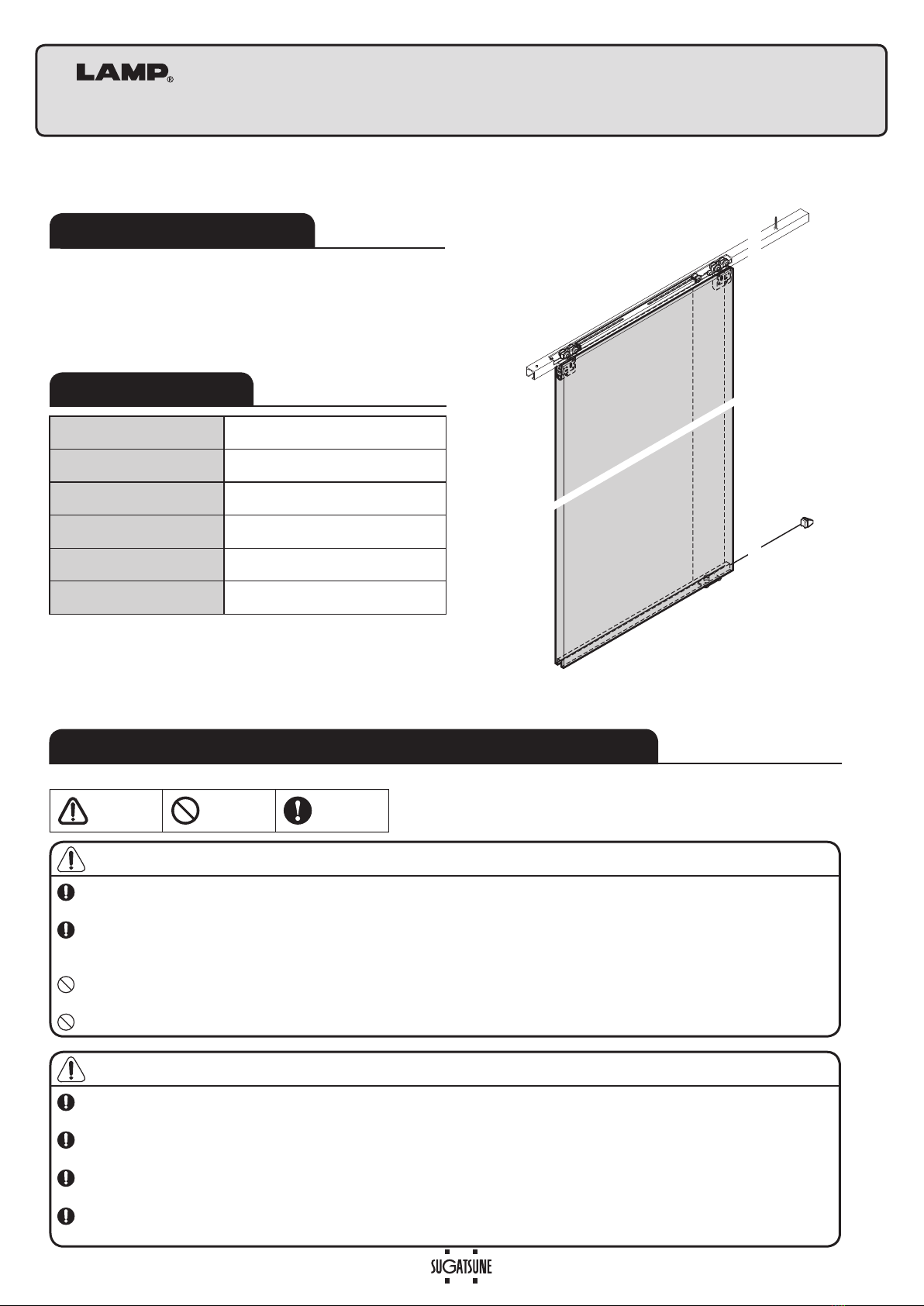
When vertical frame is not
used, use door stopper
without fail.
Door stopper
右
上
下
左
Lever
Tighten
2 mm
2 mm
Be sure to tighten the nut
to prevent damaging parts.
Caution
PERIODICAL INSPECTION
・Clean inside of track.
・Check upper space and lower space of the door. If necessary, correct the space.
Final confirmation
Confirm that all screws are securely tightened. And, confirm that all screws are used without mistake.
TROUBLESHOOTING
4. Adjusting the Door Position
Adjust the door so that it is parallel to the upper track with 6 - 13 mm of clearance
EHWZHHQWKHGRRUDQGÀRRU
Do not turn adjustment screw
beyond adjustment range.
Do not use electric
screw driver.
Vertical adjustment range: 7 mm
Depth adjustment range: 4 mm
9HUL¿FDWLRQRI6OLGLQJ'RRU&ORVHU2SHUDWLRQ
【1】Remove the support from under the door.
【2】Close the door slowly and check that the soft closer works
correctly. The soft closer is engaged approximately 100 mm
DWWKHOHDGLQJHGJHEHIRUHWKHGRRUUHDFKHVLWV¿QDOSRVLWLRQ
【3】Please refer to the "Troubleshooting" section
when the soft closer does not work correctly.
Caution
Do not close the door with excessive force. It may cause
damage to the soft close mechanism.
Trigger (crimping)
Frame
Jump prevention nut
Vertical position
adjustment screw
右
上
下
左
7
3 mm
4 mm Clockwise = Up
Counterclockwise = Down
Depth
adjustment screw
右
上
下
左
±2 mm
The adjustment of the door should be done
with the jump prevention nut loosened.
Caution
Trouble Checkpoint Solution
Door stops during soft
closing
&KHFNLIGRRUERWWRPFRQWDFWVZLWKÀRRU 9HULI\WKDWWKH WUDFN¿[LQJVFUHZVDUH QRWORRVHQHG7KHQDGMXVWWKHGRRU KHLJKW
VXFKWKDWWKHFOHDUDQFHEHWZHHQWKHGRRUERWWRPDQGÀRRULVPP
Check if the upper track is set horizontally. Using a level gauge, reset upper track horizontally.
Check if mohair seal is installed. Reduce the friction between mohair and door.
No soft closing Check if trigger is installed. Install trigger to correct position.
Check if door is closed by excessive force. Do not close door by excessive force as it may damage soft closer.
The position of the trigger catcher may become dislocated
(See section -4.)
Check the status of the trigger catcher in section -4.) .
Abnormal noise during
operation
&KHFNLIGRRUERWWRPFRQWDFWVZLWKÀRRU 9HULI\WKDWWKH WUDFN¿[LQJVFUHZVDUH QRWORRVHQHG7KHQDGMXVWWKHGRRU KHLJKW
VXFKWKDWWKHFOHDUDQFHEHWZHHQWKHGRRUERWWRPDQGÀRRULVPP
Check if door touches adjacent parts. Correct door position to avoid contact with adjacent objects.
$GMXVWSRVLWLRQRIWKHÀRRUJXLGH
Check track rollers for aluminum dust. Remove the track and pull out the roller. Then, clean the roller.
Check for loose screws retaining the upper track. Tighten the screw.
Heavy door operation &KHFNLIGRRUERWWRPFRQWDFWVZLWKÀRRU 9HULI\WKDWWKHWUDFN ¿[LQJVFUHZVDUHQRWORRVHQHG7KHQDGMXVW WKHGRRUKHLJKW
VXFKWKDWWKHFOHDUDQFHEHWZHHQWKHGRRUERWWRPDQGÀRRULVPP
Check if door touches adjacent parts. Correct door position to avoid contact with adjacent objects.
$GMXVWSRVLWLRQRIWKHÀRRUJXLGH
Door does not move. Check the track retaining screws for looseness. Retighten screws to free the roller.
Door starts to move. Check if the upper track is set horizontally. Using a level gauge, reset upper track horizontally.
1
1