SUHNER UAC 30-RF User manual
1
Original operating instructions
Milling and grinding motor
Type UAC 30-RF
Article No. 64 005
OTTO SUHNER GmbH
D-79713 Bad Säckingen
Phone: +49 (0) 77 61 557 0
Fax: +49 (0) 77 61 557 190
http://www.suhner.com
mailto: info.de@suhner.com
OTTO SUHNER AG
CH-5201 Brugg
Phone:+41 (0) 56 464 28 28
Fax: +41 (0) 56 464 28 33
http://www.suhner.com
mailto: info@suhner.com
465010/12-20

2
Contents
1. Safety instructions
1.1 General safety instructions
1.2 Intended use
1.3 Improper use
1.4 CE-conformity declaration
1.5 Explanation of symbols
2. Commissioning
2.1 Prior to commissioning
2.2 Commissioning
2.3 Technical data
2.4 Operating conditions
3. Handling / operation
3.1 Protection
3.2 Insertion tools
3.3 Working instructions
4. Maintenance
4.1 Preventive maintenance
4.2 Spare and waring parts
4.3 Repair
4.4 Warranty
4.5 Storage
4.6 Disposal / environmental compatibility

3
1. Safety instructions
1.1General safety instruction
These operating instructions apply to the UAC 30-RF device. These
machines are to be handled solely by personnel qualified according to EN
60204-1.
The enclosed, separate safety instructions are to be strictly observed.
1.2Intended use
The built-in milling and grinding motor is intended for milling work in wood
and plastic, and for grinding wood, plastic, steel and aluminium.
1.3Improper use
Any use other than described in Item 1.2 shall be deemed improper use and
is, therefore, not permissible.
1.4. EC-conformity declaration (original)
Otto Suhner GmbH, Trottäcker 50, D- 79713 Bad Säckingen hereby
declares in sole responsibility that the product with the serial or batch
number (see reverse) meets the requirements of guidelines 2014/30/EU,
2014/35/EU;2006/42/EG. Applicable standards: EN ISO 12100, IEC 60745,
IEC 62233; IEC 61000-6-2; IEC 61000-3-2, IEC 61000-3-3.
Document commissioner: T. Fischer
Bad Säckingen, May 2020
T. Fischer
Head of Division

4
Explanation of symbols
Caution!
Be sure to read this!
This information is crucial to warranting the product’s function. Failure to
observe may result in a defect.
Safety instruction / warning
This information serves achieving safe operation. If you fail to observe it, the
operator’s safety will not be warranted.
Information
This information serves better understanding of the product’s function. It
helps exploit the full capacity of the product.
Operating instructions
Read operating instructions prior to commissioning the product.
Safety glasses and ear protection
Wear safety glasses and ear protection.
Disposal
Environmentally friendly disposal
Power plug
Unplug power supply prior to working on the machine.

5
2. Commissioning
2.1 Prior to commissioning
Verify mains voltage. The voltage of the power supply has to match the
details on the rating plate.
§Check the tool before use.
§The tool must be mounted centrically and positioned at the stop.
§Do not exceed the permissible speed of tool and chuck in any case.
§Country-specific regulations are to be observed.
§Take protective measures when working harmful, flammable or explosive dust
may be generated during work. Wear a dust mask and, if attachable, use dust/chip
extraction.
2.2 Commissioning
Preselect rpm using the hand wheel.
During operation, never increase speed to match the insertion tool.
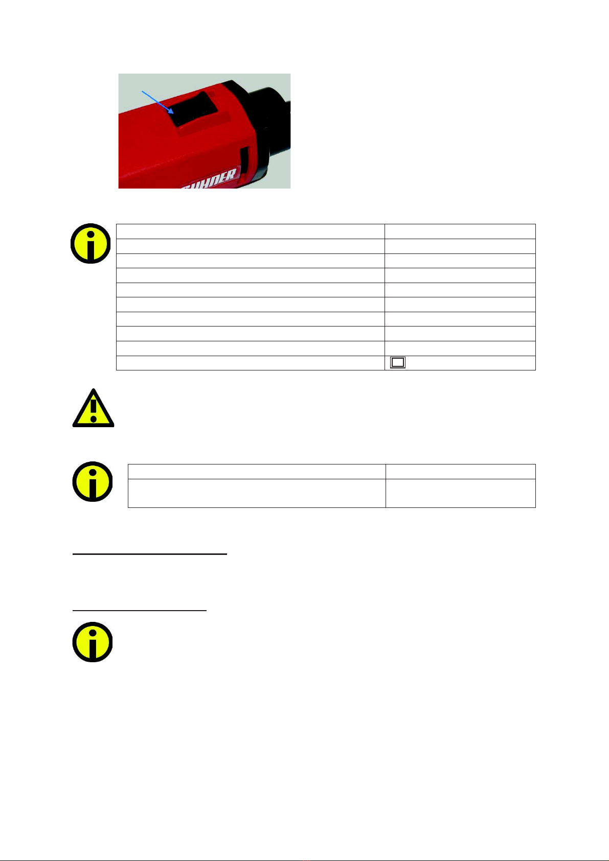
Switching on
The switch has to be in OFF position, i.e.
you see
<< 0 >>. To switch the machine on, push
the switch forward until you hear it click
into place, i.e. you see the <<1>>.
Wheel position min-1/rpm
6
30 000
5
25 000
4
20 000
3
14 000
2
8 000
1
3 500
6
Switching off
Pressing the ON/OFF switch unlocks it so
the machine turns off.
2.3 Technical data
The specified vibration value was measured according to a standardised
test procedure and may differ from the value during actual operation. It may
be used for product comparison or for an initial assessment of exposure.
2.4 Conditions
Operating temperature range
0 to + 50 °C
Relative humidity
10 - 95 % non-
condensed
3. Handling / operation
3.1 Protection
3.1.1 Machine protection
§Start-up current limiter
The electronically controlled smooth start lets the device start up without
jerking. Due to the device’s low start-up current, a 16A fuse is sufficient.
§Temperature-dependent overload protection
To protect the device against overheating, the electronic safety feature
switches into cool-down mode once a critical temperature has been
reached. The machine keeps running at a significantly reduced speed and
the electronic constant-speed control is deactivated.
Supply voltage (see spare part list)
230V 50/60 Hz
Power input
500 W
Power output
300 W
Idle speed
3 500 –30 000 min -1
Max. tool diameter
35 mm
Collet chuck max. diameter
6 mm
Sound pressure level EN 60745
73 dB, K= 3dB
Vibration EN 60745
5.0 m/s², K=1.5m/s²
Weight without cable Kabel
1.3 kg
Ingress protection
/ II

7
After a cooling time of approx. 10-20 sec., the machine is ready to operate
again. Switch it of and on again to reactivate the electronic constant-speed
control.
When the device is at operating temperature, the temperature-dependent
overload protection will react sooner.
3.2 Insertion tools
Only use insertion tools whose maximum permissible rotation speed is
equal to or higher than the idle speed of the device.
Insert clean tools only!
Unplug the device from the power outlet before making any device
adjustments, changing accessories, or putting the device away. This
precaution prevents the unintentional start of the device.
Wear protective gloves when changing the tool. The insertion tool may
heat up considerably during longer work processes and/or cutting edges of
the insertion tool are sharp.
3.2.1 Changing / assembling the insert tool
1) Steady the work spindle at the
wrench flat using a gauge 17 open-ended
wrench.
2) Loosen the clamping nut using a
gauge 17 open-ended wrench.
3) Insert the clamping shank into the
chuck as far as it will go.
4) Tighten the clamping nut
8
The grinding tools must rotate perfectly true. Do not continue to use out-of-
true.
Test run!
Check grinding tools prior to using them. The grinding tool must be mounted
perfectly and rotate freely. Perform test run without load for at least 30
seconds. Do not use damaged, untrue or vibrating tools!
3.3 Working instructions
Working with the milling motor
Wear glasses and ear protection
When using a drill stand or a drill and milling bench - possibly in conjunction with a
milling table –observe the information in the operating instructions enclosed with the
same.
In addition, make sure that the ruler stops are brought as closely to the milling cutter
as possible, the hand deflector (sight protection) is brought down as close as
possible to the workpiece surface and that, when milling, you always use devices that
will safeguard safe guiding of the workpiece, e.g. ruler stop, auxiliary stop, feed slide
or stop block for insert milling work.
Always feed the workpiece in the opposite direction of the rotation of the milling tool
(counter rotation):
Attention! Always mill in counter rotation!
Use only sharp milling tools in good condition! For best results, use our
original milling tools.
When using other milling tools, do not exceed the rpm specified by their
manufacturers on the rotating tools!
Milling process
Keep your hands away from the milling area and the milling cutter. Always
hold the additional handle with your other hand.
When you hold the milling machine with both hands, they cannot be injured
by the cutter.
only guide the power tool against the workpiece when it is switched on.
Otherwise, you risk a kickback if the insert tool gets caught in the
workpiece.

9
4. Maintenance / service
4.1 Preventive maintenance
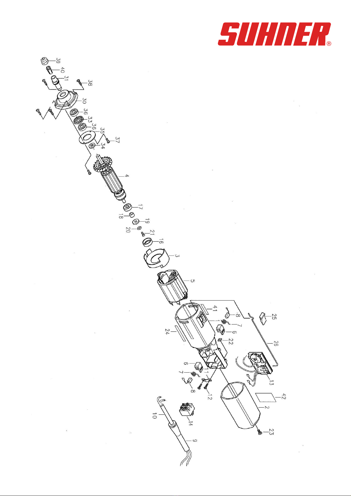
4.1.1 Changing the brush
Unplug power supply prior to any maintenance work.
The machine is equipped with two carbon brushes.
Change the brushes as follows:
Fig. 1 Fig. 2
.
Unscrew fastening screw (Pos. 23)
on the
switch cap (Pos. 2).
Pull the switch cap (Pos.2) back a little.
Fig. 3 Fig. 4
Pull the connector of the carbon brush (Pos.
8)
out to disconnect and
remove the worn
out carbon
brush from the brush holder
(Pos.
6).
Install new brushes (Pos. 8) in reverse
order.
The brushes have to be easy to move.
After
you have exchanged
the brushes,
there will be a little more brush sparking
initially, however after a short while, this
will
be reduced to the normal, slight,
blueish
-white brush sparking.
10
Typ UAC 30-RF
Artikel
-Nr. 64 005
This manual suits for next models
1
Table of contents
Other SUHNER Engine manuals


