Inhaltsverzeichnis
4 01.02/ERS 135-210 048V/en
6.2 Requirements for the power and sensor cables ........................................................... 26
6.3 Option brake .................................................................................................................. 26
6.3.1 Technical data for brake valve MV15 .......................................................... 27
6.3.2 Connection to the MCS 12 controller ........................................................... 28
6.3.3 Holding brake moment ................................................................................... 28
7 Description of the module............................................................................. 29
7.1 ERS torque motor............................................................................................................ 29
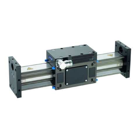
7.1.1 Design and description of the ERS................................................................. 29
7.1.2 Mechanical interfaces..................................................................................... 30
7.1.3 Elektrische Schnittstellen.................................................................................. 31
7.1.4 Type key and nameplate................................................................................ 32
8 Assembly ..................................................................................................... 33
8.1 Mechanical connection.................................................................................................. 33
8.2 Electrical connection....................................................................................................... 36
9 Connection and operating with SCHUNK controller MCS 12 ......................... 38
9.1 Scope of delivery of MCS 12 ....................................................................................... 40
9.2 Technical Data of the MCS 12 controller..................................................................... 41
9.3 Design and description of MCS 12 .............................................................................. 43
9.4 Assignment of the terminal strips of the MCS 12 ......................................................... 46
9.4.1 Assignment of terminal strip X1 ...................................................................... 46
9.4.2 Assignement of terminal strip X2 .................................................................... 47
9.4.3 Assignement of terminal strip X3 .................................................................... 47
9.4.4 RS232 connection........................................................................................... 48
9.4.5 CAN connection.............................................................................................. 48
9.4.6 Profibus DP connection ................................................................................... 49
9.5 Connection of the interfaces of the MCS 12................................................................ 50
9.5.1 Assignment of terminal X1 .............................................................................. 50
9.5.2 Assignment of terminal X2 .............................................................................. 50
9.5.3 Assignment of terminal X3 .............................................................................. 50
9.5.4 Assignment of RS232...................................................................................... 50
9.5.5 Assignment of CAN......................................................................................... 50
