komodo KH-283 User manual
Komodo Hobby
Building Instruction
&
Manual
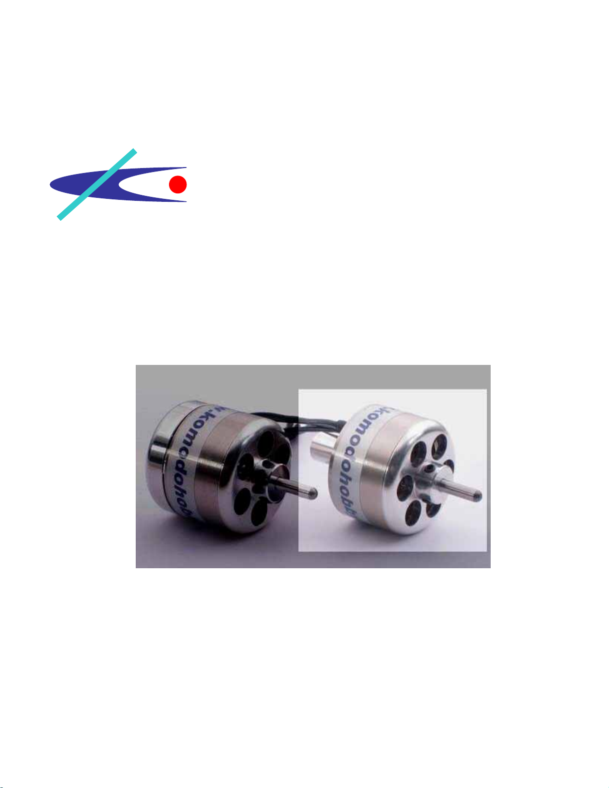
KH -283 Outrunner Motor Kit Version 2
(Stick Style)

Komodo Hobby
www.komodohobby.com
1
Introduction
Congratulations on your purchase of KH-283 Outrunner Motor Kit Version 2. KH-283 V.2 is a modified
motor kit designed for powering 3D and Aerobatics RC airplanes. Modelers can choose either back
mount style or stick style to meet the airplane requirement.
KH-283 V.2 powered with 2mm thickness curved NdFeB magnets. It delivers excellent acceleration for
hovering and performing aggressive 3D aerobetic maneuvers. By the latest design of 9 degrees
magnet gap, the motor can be started-up and run smoothly.
KH-283 V.2 motor kit includes high quality hardened steel main shaft and pre-assembled precision
end-bell and flux ring. Those parts are produced by advanced technology. It allows the motor running
at high rpm without vibration. Motor builders can utilize three-screw lock system to install and change
main shaft without gluing. If you are a serious motor builders or modelers, Komodo Outrunner Motor kit
is the only choice for you.
Warning
Radio Control Model and Outrunner Motor Kit are not toy!!! It contains sophisticated small parts and is
designed for hobby use only. All parts of this outrunner motor kit have to be assembled and operated
with great care. Outrunner motor can produce very high power to turn gear or spin propeller. It is
capable of causing property damage and all bodily harm to operator or spectators. If you are a
beginner of motor builder, please seek assemble and operational help from experienced motor builder.
Be caution!!!
If this outrunner motor kit is not assembled and operated properly, it can destroy your electronic speed
control, receiver, batteries and relevant equipment completely.
Parts List
(QTY) Items
(1) Pre-pressed End-Bell and Flux Ring
(2) 23.8mm Stator
(2) Ball Bearings
(1) 3.17mm Hardened Steel Shaft
(1) 40feets, AWG 23 Enameled Magnet Wire
(12) NdFeB Curved Magnets
(1) Propeller Saver
(2) Propeller Saver Replacement Rings
(1) O’ring
(3) Connector Pairs (Male and Female)
(7) Shrinking Tubes
(3) M3 x 4 Screws
(2) M3 x 8 Screws
(1) C-Clip
(1) Bearing Tube
Komodo Hobby
www.komodohobby.com
2
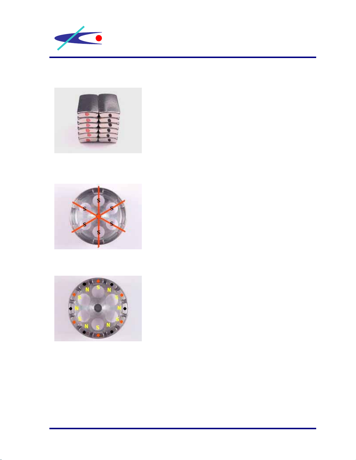
1. Marks color to magnets
2. Place magnets inside the bell
Use marker to mark different color to North Pole
and South Pole.
First, place six South Pole magnets inside the bell
and aligned it with six vent holes. Then, use a drop
of CA to secure the position of magnet.
Second, place six North Pole magnets in between
South Pole magnets. Use a small clip to adjust the
magnets until all magnets placed evenly. Then, use
a drop of CA to secure the position of magnet.
Komodo Hobby
www.komodohobby.com
3
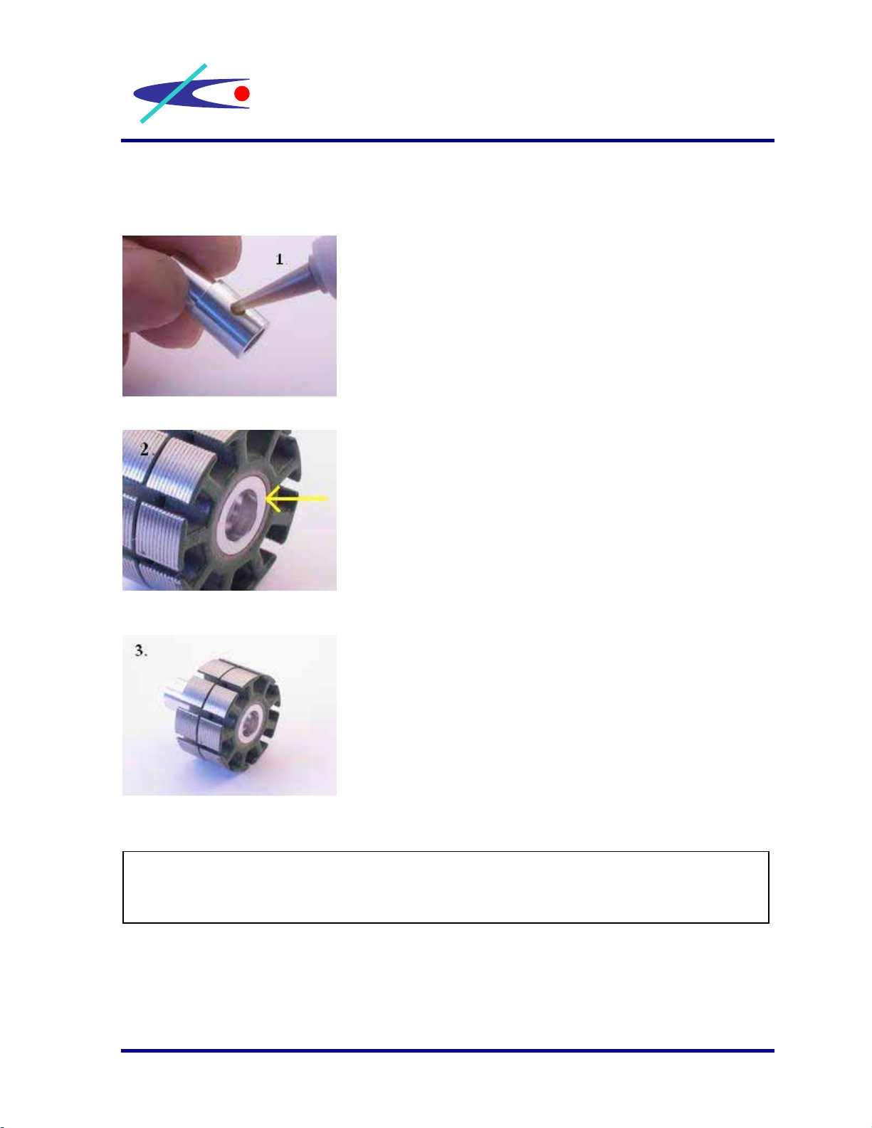
3. Insert Bearing Tube into Two Stators
First, put Loctite to the whole area of bearing tube
shoulder.
Second, insert the bearing tube into two stators until the
bearing tube shoulder touch the edge of stator.
Third, align the stator teeth and wait for the Locitite dry.
After the Locitite dry, you can go to the next step, Winding.
Komodo Hobby
www.komodohobby.com
4
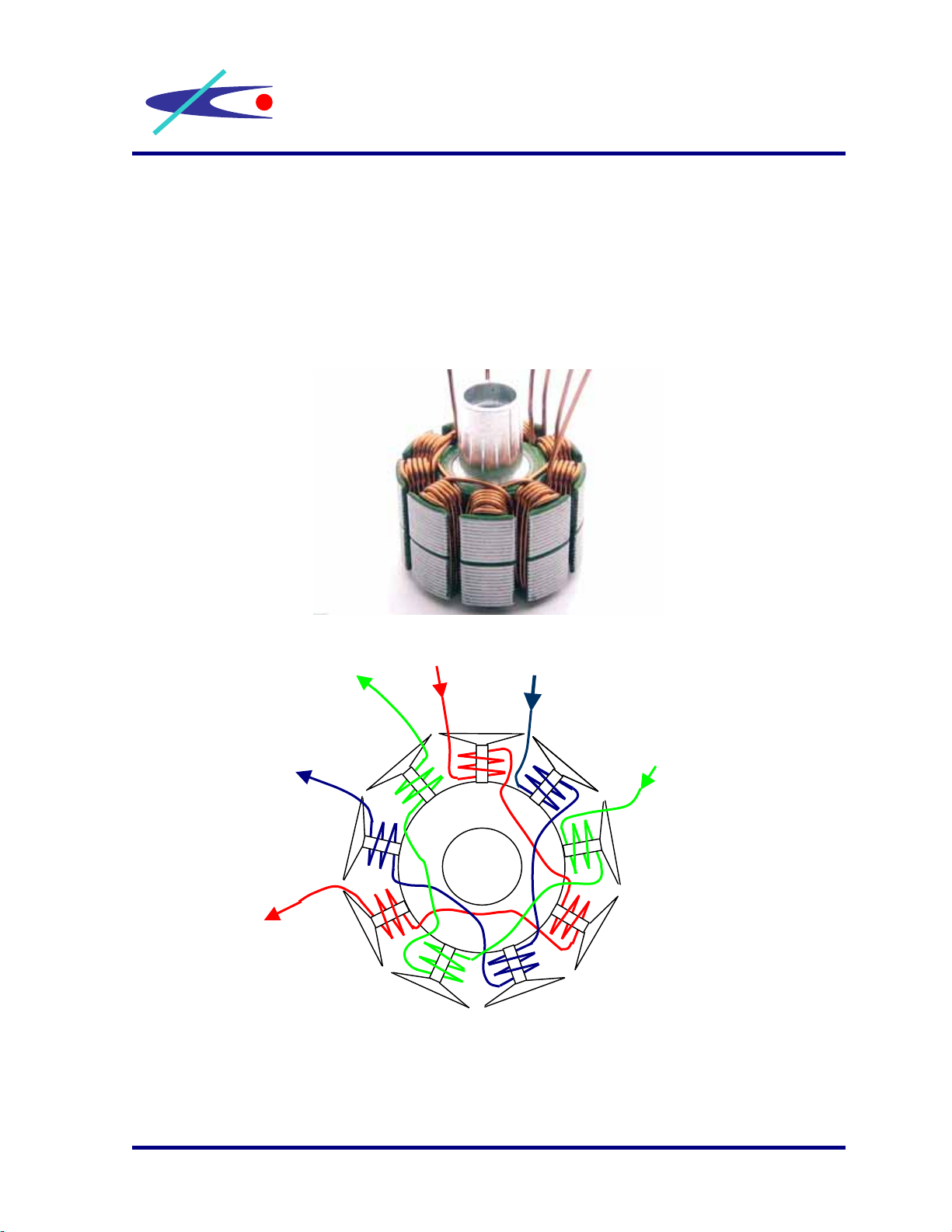
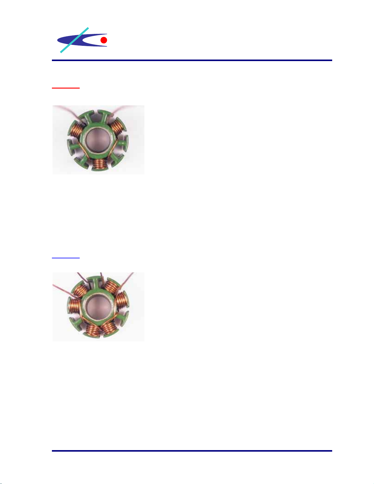
4. Winding
It is an example of using three individual magnet wires to complete a 3-phases
system. We recommend beginners to wind 10turns for their first motor. For
experienced motor builders, they can wind more or less turns to get different
potential power. Note: Since the last turn is not a complete circle, you need to
wind 11times to get 10turns’ power. Make sure that every coil has same number
of windings.
Diagram of winding system of 9-pole stator
65
E1
E2
E3
S3
S1 S2
7
8
9
12
3
4
Komodo Hobby
www.komodohobby.com
5
Phase 1
Phase 2
Step (1): Remain 7-8cm long magnet wire for
connection use afterward.
Use magnet wire “S1” to start to wind
11times in clockwise direction at tooth No.1.
Wind from the hub to the outer edge of
hammerhead then back to the hub.
Step (2):Jump to tooth No. 4 and start to wind
11times in clockwise direction as step (1).
Step (3):Jump to tooth No. 7 and start to wind
11times in clockwise direction as step (2).
Step (4):Cut the magnet wire “S1”. This ending of
wire will be called “E1” in the following
steps. Note: Remain 7-8cm long magnet
wire for connection use.
Step (5): Remain 7-8cm long magnet wire for
connection use afterward.
Use magnet wire “S2” to start to wind
11times in clockwise direction at tooth No.2.
Wind from the hub to the outer edge of
hammerhead then back to the hub.
Step (6): Jump to tooth No. 5 and start to wind
11times in clockwise direction as step (5).
Step (7): Jump to tooth No. 8 and start to wind
11times in clockwise direction as step (6).
Step (8): Cut the magnet wire “S2”. This ending of
wire will be called “E2” in the following
steps. Note: Remain 7-8cm long magnet
wire for connection use.

Komodo Hobby
www.komodohobby.com
6
Phase 3
3. Remove the coating of magnet wires
Step (9): Remain 7-8cm long magnet wire for
connection use afterward.
Use magnet wire “S3” to start to wind
11times in clockwise direction at tooth
No.3. Wind from the hub to the outer edge
of hammerhead then back to the hub.
Step (10): Jump to tooth No. 6 and start to winds
11times in clockwise direction as step (9).
Step (11): Jump to tooth No. 9 and start to wind
11times in clockwise direction as step (10).
Step (12): Cut the magnet wire “S3”. This ending of
wire will be called “E3” in the following
steps. Note: Remain 7-8cm long magnet
wire for connection use.
When you finish the winding steps above, you have 6
endings of magnet wire attached to coils. Use a shape
model knife to scrape off the coating of these six magnet
wires.
Then, it is necessary to check any short between
magnet wire and stator metal, and need to check any
short between magnet wires, S1, S2 and S3. If you find
any short between them, please be patience to rewind
them again.
Note: your Electronic Speed Controller, Receiver and
Battery can be destroyed by part defect of windings.

Komodo Hobby
www.komodohobby.com
7
4. Solder magnet wires to Delta or Wye system
Now, you can make you own decision to solder the magnet wires to either Star
(wye) or Delta system.
Star vs Delta
9Star (wye) system gives more torque and uses fewer amps.
In Star system, 1.73 less turns needs to be wound to get the same power and
Kv as DELTA system does.
9Delta system gives 1.73 higher power and amps draw compare to STAR
system.
In Delta system, the Kv is 1.73 higher than Star system while the Kt (Torque)
is 1.73 lower
Star (wye) system
6 5
Solder E1, E2 & E3
Together
S3
S1 S2
7
8
9
12
3
4

Komodo Hobby
www.komodohobby.com
8
5. Insert three soldered wires to Shrinking Tubes
6 5
Delta System
Solder
E3 to S1
7
8
9
12
3
4
Solder
E1 to S2 Solder
E2 to S3
Now, you have three soldered
wires attached to coils. Insert
those soldered wires into
shrinking tubes for insulating.
Komodo Hobby
www.komodohobby.com
9
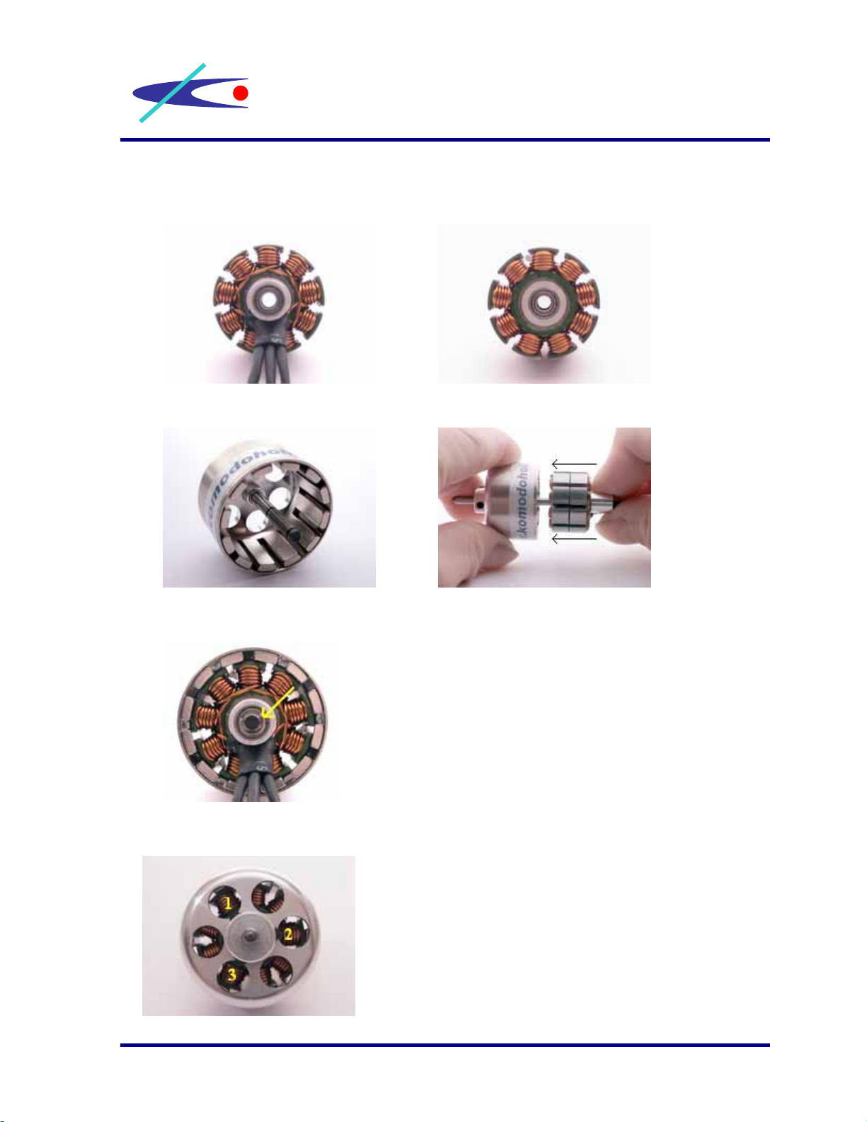
6. Place ball bearings to bearing tube.
7. Insert a main shaft to endbell and put the wound stator into the bell.
8. Put a c-clip to the slot of main shaft.
9. Place three screws at the end-bell.
Put a C-clip to the slot of main shaft to secure whole
motor system.
Place three M3 x 4 screws to end bell to secure the
position of main shaft. Each screw must be turned a
bit by each time until all screws tighten up.
Other komodo Engine manuals


