Suisei RC-G4B User manual

RC-G4B
RC-G8B
Instruction
Manual
SUISEI ELECTRONICS SYSTEM CO., LTD.
Thank you for choosing RC-G4B/RC-G8B.
If you have any inquiry regarding the product, please contact us or our sales agency.
For your information, the content of this manual may change without prior notice.
Please check our website for the latest information; http://www.suisei.co.jp.
1st Edition

(2/13)
1st Edition : issued in March 2018
Copyright C 2018 Suisei Electronics System Co.,Ltd.
This product is a writing device only for one chip microcomputer with built-in flash ROM,EPROM
and onetime PROM produced by Renesas Electronics Corporation. If can not be used for writing
to other devices and for other purposes.
Warranty period for this product is one year after from the date of the purchase. Fault(s) cause
by the defect(s) in manufacturing will be repaired without charge during this period. Please notify
the local distributor or us.
Please note a fault of the consumables such as a socket and a switch will be repaired at your
expense. A fault of MCU device written by this product and an error caused by the fault
accordingly will not be warranted.
In case this product is used for mass production, please make sure to consider usage
environment, etc. in advance by yourself and to check the reliability.
In case this product is used in Japan, Electrical Appliance Regulations and electromagnetic
interference measures will not be applied.
This product obtains neither safety standard such as UL nor standard such as IEC. Please be
aware of this point when you bring it outside Japan.
The content written in this manual may be revised without notice on account of performance
improvement, etc.
Our has used reasonable care in preparing the information included in this document, but our
does not warrant that such information is error free. Also our assumes no liability whatsoever for
any damages incurred by you resulting from errors in or omissions from the information included
herein.
For enquiries on the content of this manual and the software, please contact the following.
For inquiries we will accept by e-mail.
To 6-5-24, Tsurumi, Tsurumi-ku, Osaka City 538-0053, Japan
Suisei Electronics System Co.,Ltd.
E-mail:support@suisei.co.jp
http://www.suisei.co.jp/

(3/13)
Index
Page
1. Overview.......................................................................................................................................................................4
2. Panel name, function description ..............................................................................................................6
3. How to connect ......................................................................................................................................................8
4. Lighting pattern of Displayed LED........................................................................................................ 10
5. T_VDD and T_VPP voltage setting switches ...............................................................................10
6. Connector for user target connection .............................................................................................. 11
7. How to operate.................................................................................................................................................... 12
8. Specifications........................................................................................................................................................13
(4/13)
1. Overview
RC-G4B/RC-G8B is a gang write unit that uses EFP-RC2 or EFP-LC and EFP-RC serial MCU
programmers (Hereinafter EFP body) to connect 1 to 8 units.
By using RC-G4B/RC-G8B, you can write and read at the same time up to 4 or 8 Renesas
Electronics flash memory built-in MCU and QzROM built-in MCU.
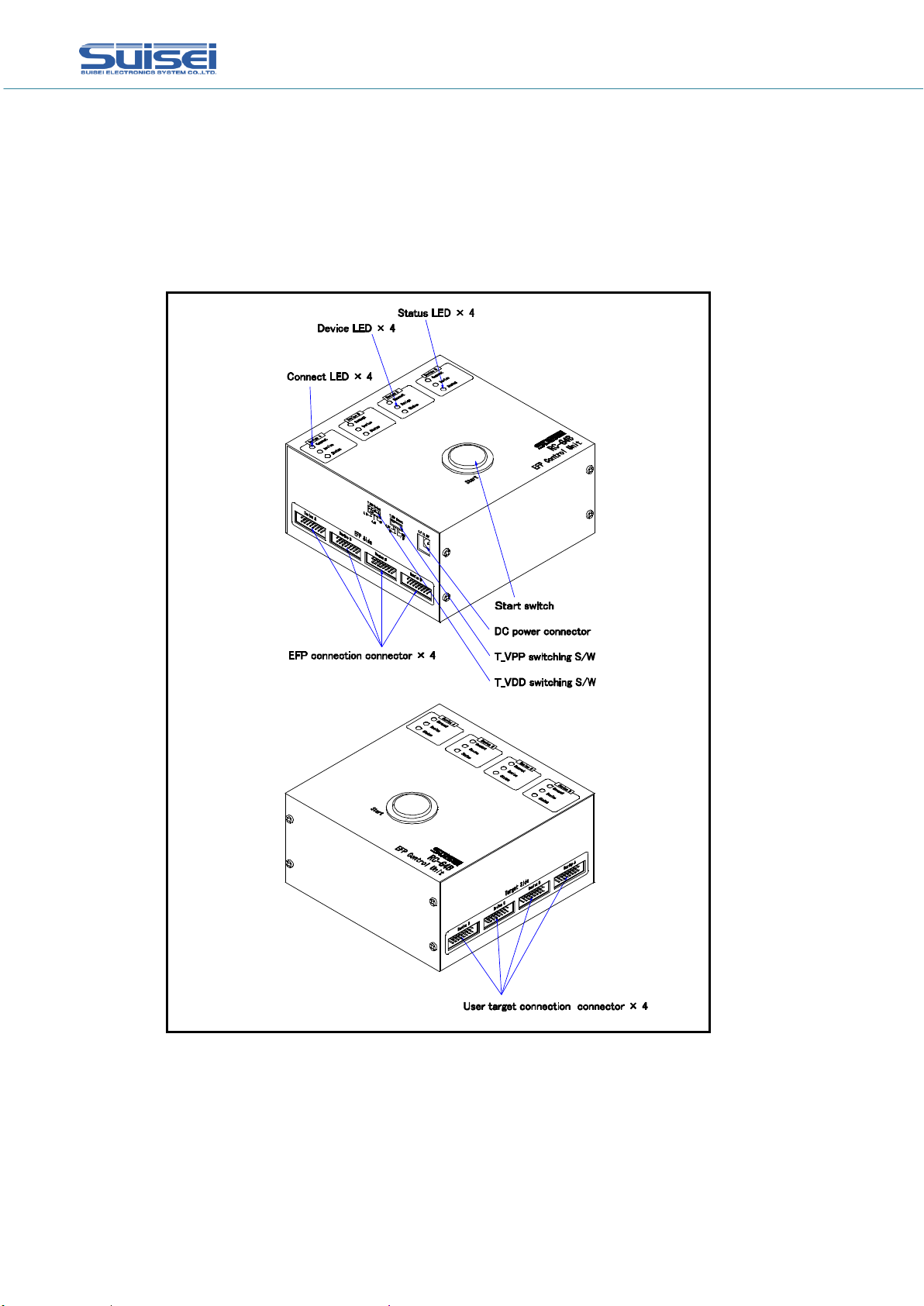
Figure 1.1 shows the outline drawing of RC-G4B, and Figure 1.2 shows the outline drawing of
RC-G8B.
Figure 1.1 RC-G4B External Figures
(5/13)
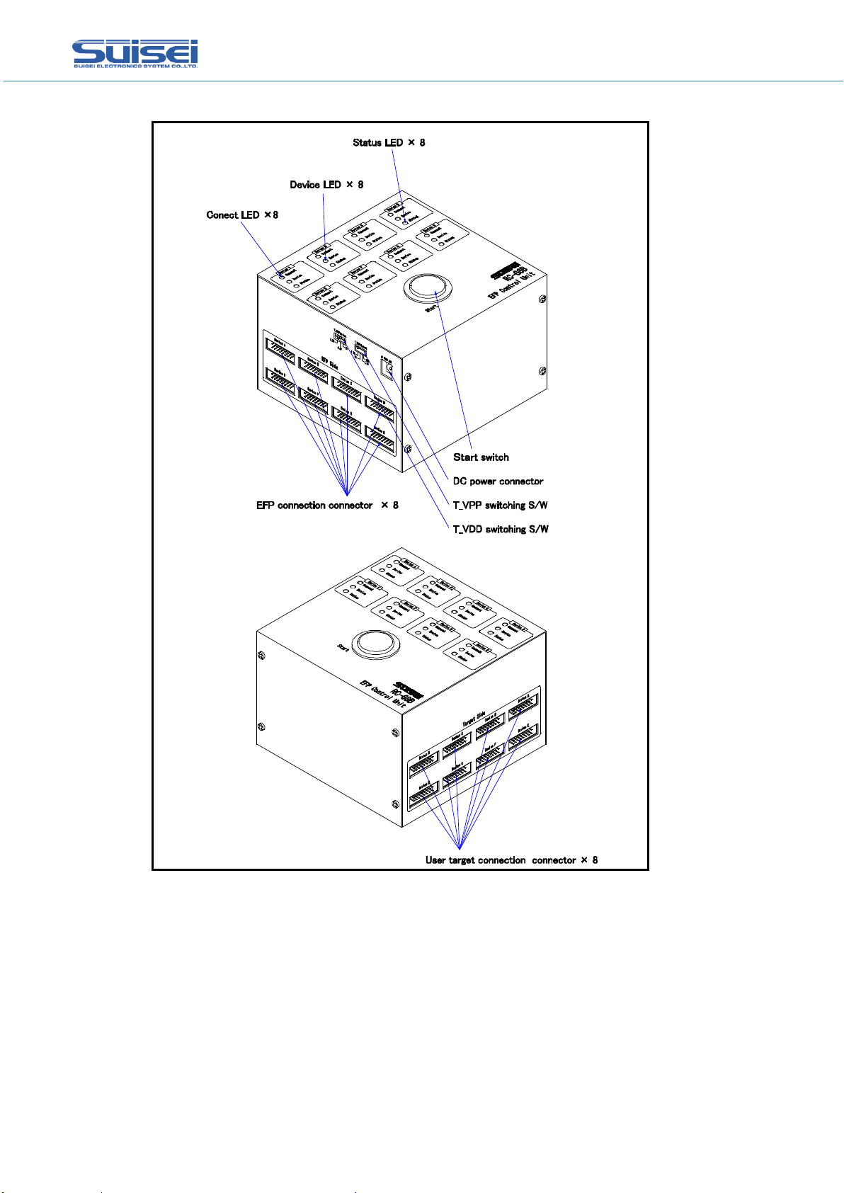
Figure 1.2 RC-G8B External Figures

(6/13)
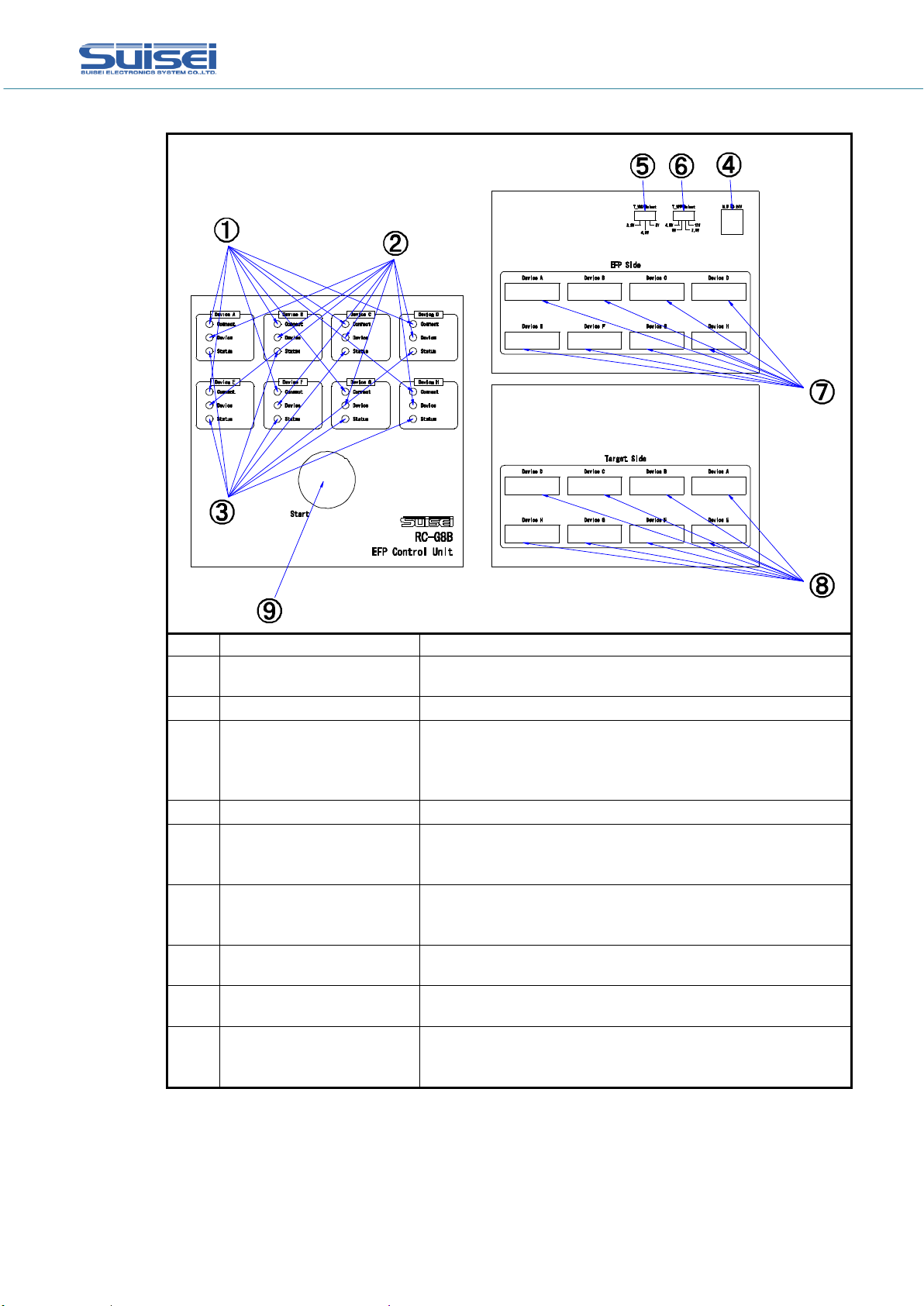
2. Panel name, function description
The names and functional descriptions of each LED, switch, and connector are shown in Figure
2.1 and Figure 2.2.
Mark
Name
Content
1
Connect LED
(Green)
Lights when the EFP body is connect.
2
Device LED(Orange)
Lights up when device command is executed.
3
Status LED
(Red/Green)
When the result of device command execution ends
normally, it will light up in "green".
When device command execution result ends in error, it
lights up in "red".
4
Power Connector
It provides DC17.5V to 24V from outside.
5
T_VDD Voltage
Setting Switch
Voltage setting switch of T_VDD to be supplied to user
target. It is possible to set the voltage of T_VDD to
3.3V, 4.5V, 5V.
6
T_VPP Voltage
Setting Switch
Voltage setting switch of T_VPP to be supplied to user
target. It is possible to set the voltage of T_VPP to
4.5V, 5V, 7.9V, 12V.
7
EFP body Connection
Connector
Connects EFP body, using EF1TGCB-16W16W.
8
User Target Connection
Connector
Connects user target, using target connection cable.
9
Start Switch
It is an operation start switch.
It is connected to the external start input terminal of
each EFP body.
Figure 2.1 RC-G4B Panel Figure
(7/13)
Mark
Name
Content
1
Connect LED
(Green)
Lights when the EFP body is connect.
2
Device LED(Orange)
Lights up when device command is executed.
3
Status LED
(Red/Green)
When the result of device command execution ends
normally, it will light up in "green".
When device command execution result ends in error, it
lights up in "red".
4
Power Connector
It provides DC17.5V to 24V from outside.
5
T_VDD Voltage
Setting Switch
Voltage setting switch of T_VDD to be supplied to user
target. It is possible to set the voltage of T_VDD to
3.3V, 4.5V, 5V.
6
T_VPP Voltage
Setting Switch
Voltage setting switch of T_VPP to be supplied to user
target. It is possible to set the voltage of T_VPP to
4.5V, 5V, 7.9V, 12V.
7
EFP body Connection
Connector
Connects EFP body, using EF1TGCB-16W16W.
8
User Target Connection
Connector
Connects user target, using target connection cable.
9
Start Switch
It is an operation start switch.
It is connected to the external start input terminal of
each EFP body.
Figure 2.2 RC-G8B Panel Figure
(8/13)
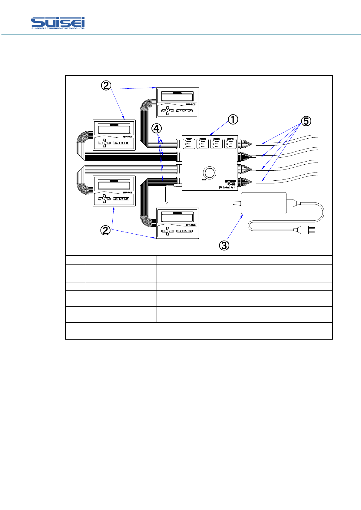
3. How to connect
Figure 3.1 and Figure 3.2 show how to connect the RC-G4B and RC-G8B.
Mark
Name
Content
1
RC-G4B
RC-G4B main body
2
EFP-RC2
EFP-RC2 main body (EFP-LC, EFP-RC can also be used.)
3
Power adapter
output : 19V, Current volume : 3.2A
4
EF1TGCB-16W16W
Connection cable between EFP-RC2 and RC-G4B, Both
sides 16PinCN processing
5
Target connection
cable
Connection cable between RC-G4B and user target, One
side 16pinCN processing
"3" to "5" are included in RC-G4B of "1". ("5" comes with EF1TGCB-16WX)
Please prepare other products separately.
Figure 3.1 RC-G4B Connection diagram

(9/13)
Mark
Name
Content
1
RC-G8B
RC-G8B main body
2
EFP-RC2
EFP-RC2 main body (EFP-LC, EFP-RC can also be used.)
3
Power adapter
output : 19V, Current volume : 3.2A
4
EF1TGCB-16W16W
Connection cable between EFP-RC2 and RC-G8B, Both
sides 16PinCN processing
5
Target connection
cable
Connection cable between RC-G8B and user target, One
side 16pinCN processing
"3" to "5" are included in RC-G4B of "1". ("5" comes with EF1TGCB-16WX)
Please prepare other products separately.
Figure 3.2 RC-G8B Connection diagram
3.1 Notes
Note1 : Please connect RC-G4B/RC-G8B and EFP body with the power supply turned off.
Note2 : When the Device LED (Orange) of the RC-G4B/RC-G8B is lit, the connection cables to
the EFP body and the user target board is energized, so do not insert / eject cables.
Note3 : Power off the RC-G4B/RC-G8B and EFP body before removing the EFP body and the
RC-G4B/RC-G8B.
Note4 : Power supply to EFP body and user target is supplied from RC-G4B/RC-G8B.
The supply current to the user target is 50mA.

(10/13)
4. Lighting pattern of Displayed LED
Figure 4.1 shows lighting pattern of displayed LED.
No.
Operation
LED
Name
Content
1
When power is turned
on
Connect
When EFP body is connected, "green" is
turned on. When EFP body is not
connected, it is turned off.
Device
Turned off.
Status
Turned off.
2
When device command
is executed
Connect
"Green" is turned on.
Device
"Orange" is turned on.
Status
Turned off.
3
After device command
is executed
Connect
"Green" is turned on.
Device
Turned off.
Status
If normally terminated, "green" is turned
on. If terminated with an error, "red" is
turned on.
Figure 4.1 Lighting Pattern of Displayed LED
5. T_VDD and T_VPP voltage setting switches
Figure 5.1 shows silk figure of T_VDD and T_VPP voltage setting switch.
Name
Content
T_VDD Select
This is a voltage setting switch of T_VDD supplied to user
target. Voltage of T_VDD can be set to 3.3V, 4.5V, or 5V.
Please set 4BitQzROM to 4.5V and 8BitQzROM to 5V.
T_VPP Select
This is a voltage setting switch of T_VPP supplied to user
target. Voltage of T_VPP can be set to 4.5V, 5V, 7.9V or 12V.
Please set both 4BitQzROM and 8BitQzROM to 7.9V.
Figure 5.1 Silk Figure of T_VDD and T_VPP voltage setting switch
Note1 : When Device LED (orange) of RC-G4B/RC-G8B main body is turned on, please do not
switch over T_VDD and T_VPP voltage setting switch.
4.5V
4.5V
3.3V 5V
T_VDD Select
5V 7.9V
12V
T_VPP Select
(11/13)
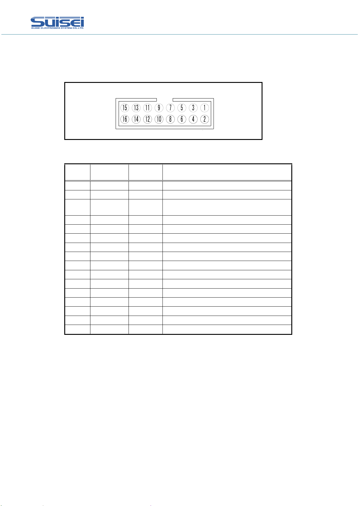
6. Connector for user target connection
Figure 6.1 shows pin allocation figure of user target connection connector.
Table 6.1 shows terminal table of user target connection connector.
Figure 6.1 Pin allocation figure of target connection connector
Table 6.1 Terminal table of user target connector
Pin NO.
Terminal
Name
Input –
Output
Explanation
1
GND
GND
2
(N.C)
-
3
T_VPP
Output
Target writing power output.
4.5V, 5V, 7.9V or 12V.
4
T_VDD
Output
Target power output. 3.3V, 4.5V or 5V.
5
(N.C)
-
6
(N.C)
-
7
(N.C)
-
8
T_PGM/OE
Output
Target writing-reading pulse.
9
T_SCLK
Output
Clock for synchronous communications
10
T_TXD
Output
Serial send data
11
T_RXD
Input
Serial receive data
12
T_Busy
Input
Target busy signal
13
(N.C)
-
14
T_Reset
Output
Target reset control signal
15
(N.C)
-
16
GND
GND
Note1 : I/O is the direction from RC-G4B/RC-G8B.
※XにはA~Dが入る。
Device X
* A to H is to be put into X.

(12/13)
7. How to operate
Below are a series of operation methods of RC-G4B/RC-G8B.
When EFP-RC2 or EFP-RC is used for RC-G4B/RC-G8B, it is necessary to set to memory
execution mode.
How to set the memory execution mode is described in the following items.
*EFP-RC2 : "EFP-RC2 Instruction Manual '5.9 How to use user memory files' "
*EFP-RC : "EFP-RC Operation Manual ' "S" key operation at menu' "
* When continuing to use, execute (7), (8) again.
Each file is made with C compiler and editor application.
To be operated with RC-Downloader
To be operated on EFP body
To be operated on RC-G4B/RC-G8B main body
** Please press start switch for more than 1 second. If time is short, EFP body will
not operate.
*** When using EFP-LC, you do not need the (4) to (6) procedure.
(1)To make user program and script file
(2)To convert user program to HXW file
(3)To download HXW file & script file to EFP body
(4)To set to memory execution mode
(5)To press start switch
(6)To select memory channel to execute
(7)To press start switch
(8)To start executing script file

(13/13)
8. Specifications
Table 8.1 Specifications
External dimensions
(Protruding parts not included)
RC-G4B
140(W)×140(D)×70(H) [mm]
RC-G8B
140(W)×140(D)×95(H) [mm]
Weight
RC-G4B
About 879g
RC-G8B
About 1091g
Supported programmer
EFP-RC2、EFP-LC、EFP-RC
8.1 Notes
Products of the following serial No. can not be used with this device.
* EFP-LC : Products before R2D00091 ( products shipped before April 2012)
* EFP-RC : Products before 5A00049 ( products shipped before February 2005)
This manual suits for next models
1
Table of contents


