7
FR
GB
DE
Présentation / Presentation / Beschreibung
Optimierung der Düngerstreuung im Vorgewende
und an Feldrändern
Präsentation des Systems
• Das Stop & Go ist ein System zur Auswertung von
Daten aus einem Spurführungs-Modul und/ oder
dazugehöriger Teilbreitenschaltung, um Unter- oder
Überdüngung in den Vorgewenden und am Feldrand
zu verhindern.
Das Produkt ist mit allen SULKY-Düngerstreuern der
X-Reihe kompatibel.
Spurführungen und Teilbreitenschaltungen sind
grundlegend für die Produkte, die
Pflanzenschutzmittel spritzen sollen.
Sie führen den Bediener und schalten automatisch
Teilbreiten der Maschine ab, um an jedem Punkt nur
einmal zu spritzen.
Das Stop & Go übernimmt also die Daten aus dem
Teilbreitenmanager einer Spritze.
Dazu müssen bei der Spurführung nur die 2 Teilbreiten
konfiguriert werden, die benutzt werden sollen.
(Siehe Kapitel - Einstellungen).
Jede Teilbreite entspricht einer Scheibe des
Düngerstreuers.
Die beiden dazugehörigen Kabel des
Teilbreitenmanager-Geräts müssen über mitgelieferte
Anschlussstecker an das Stop & Go angeschlossen
werden.
A
3
Optimisation des épandages d’engrais en
fourrières et bordure de parcelle
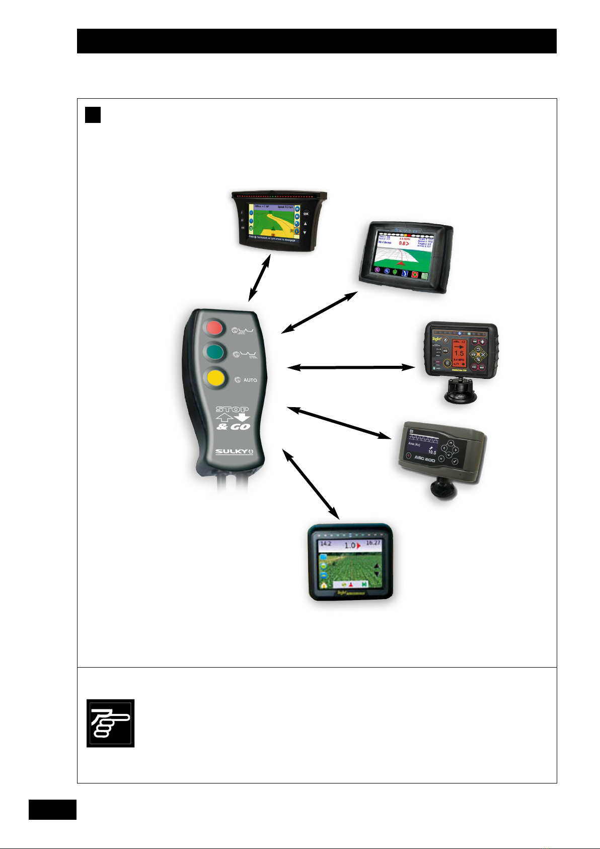
Présentation du système
• Le Stop & Go est un système capable de récupérer
les données provenant d’une barre de guidage et/ou
sa coupure de tronçons afin d’éviter les surdosages
et sous-dosages en fourrières et en bordure de
parcelle.
Le produit est compatible avec tous les épandeurs X
de la gamme SULKY.
Les barres de guidage et coupures de tronçons sont
à la base des produits destinés à la pulvérisation de
produits phyto-sanitaires.
Ils permettent de guider l’utilisateur, ainsi que de
couper automatiquement chaque tronçon de la
machine afin de ne pulvériser qu’une seule fois en
tout point.
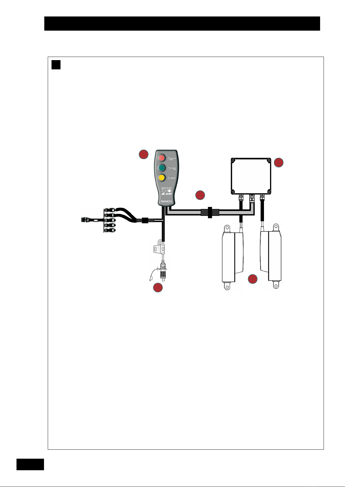
Le Stop & Go se sert donc des données sortant du
module de gestion des tronçons d’un pulvérisateur.
Pour cela, il suffit de configurer, au sein de la barre
de guidage, 2 tronçons à utiliser
(voir chapitre - Réglages ).
Chaque tronçon correspondra à un disque du
distributeur d’engrais.
Les 2 fils correspondants, sortants de la gestion des
tronçons, doivent être reliés au Stop & Go par une
connectique qui est fournie.
A
3
Optimising fertilizer spreading in headlands and
field borders.
Description of the system
• The Stop & Go system is able to retrieve the data
from a lightbar and/or its boom section control system
in order to prevent over- and under-application in
headlands and field borders.
The product is compatible with all the X spreaders in
the SULKY range.
Lightbars and boom control systems are used for
controlling pesticide sprayers.
They provide guidance for the user as well as
automatically shutting off boom sections to ensure that
each part of the field is sprayed only once.
The Stop & Go unit is therefore able to use the data
provided by the sprayer’s boom section control module.
All you need to do to make this possible is configure 2
boom sections to be used within the lightbar
(see section - Settings).
Each boom section will correspond to a fertilizer
spreader disk.
The 2 corresponding wires that come out of the boom
section control system should be connected to the Stop
& Go using the connector supplied.
A
3
A
A
A
1
1
7