Suministros Orozco Telwin digital spotter 9000 User manual

- 1 -
Cod.954013
GB I F E D RU P
GR NL H RO S DK N
SF CZ SK SI HR/SCG
LT EE LV BG PL
GB INSTRUCTION MANUAL
I MANUALE D’ISTRUZIONE
F MANUEL D’INSTRUCTIONS
E MANUAL DE INSTRUCCIONES
D BEDIENUNGSANLEITUNG
RU РУКОВОДСТВОПОЛЬЗОВАТЕЛЯ
P MANUAL DE INSTRUÇÕES
GR ΕΓΧΕΙΡΙΔΙΟΧΡΗΣΗΣ
NL INSTRUCTIEHANDLEIDING
H HASZNÁLATI UTASÍTÁS
RO MANUALDEINSTRUCŢIUNI
S BRUKSANVISNING
DK INSTRUKTIONSMANUAL
N BRUKERVEILEDNING
SF OHJEKIRJA
CZ NÁVODKPOUŽITÍ
SK NÁVODNAPOUŽITIE
SI PRIROČNIKZNAVODILIZAUPORABO
HR/SCG
PRIRUČNIKZAUPOTREBU
LT INSTRUKCIJŲKNYGELĖ
EE KASUTUSJUHEND
LV ROKASGRĀMATA
BG РЪКОВОДСТВОСИНСТРУКЦИИ
PL INSTRUKCJAOBSŁUGI
GB Spot welders
I Puntatrici
F Postes de soudage par points
E Soldadoras por puntos
D Punktschweißmaschinen
RU Точечныеконтактныесварочныемашины
P Aparelhos para soldar por pontos
GR Πόντες
NL Puntlasmachines
H Ponthegesztő
RO Aparatdesudurăînpuncte
S Häftsvetsar
DK Punktsvejsemaskinens
N Punktsveisemaskiner
SF Pistehitsauskoneet
CZ Bodovačka
SK Bodovačka
SI Točkalnik
HR/SCG Strojzatočkastovarenje
LT Taškinio suvirinimo aparatas
EE Punktkeevitusmasin
LV Punktmetināšanasaparāts
BG Апаратзаточковозаваряване
PL Spawarka punktowa

- 2 -
GB EXPLANATIONOFDANGER,MANDATORYANDPROHIBITIONSIGNS.
I LEGENDASEGNALIDIPERICOLO,D’OBBLIGOEDIVIETO.
F LÉGENDESIGNAUXDEDANGER,D’OBLIGATIONETD’INTERDICTION.
E LEYENDASEÑALESDEPELIGRO,DEOBLIGACIÓNYPROHIBICIÓN.
D LEGENDEDERGEFAHREN-,GEBOTS-UNDVERBOTSZEICHEN.
RU ЛЕГЕНДАСИМВОЛОВБЕЗОПАСНОСТИ,ОБЯЗАННОСТИИЗАПРЕТА.
P LEGENDADOSSINAISDEPERIGO,OBRIGAÇÃOEPROIBIDO.
GR ΛΕΖΑΝΤΑΣΗΜΑΤΩΝΚΙΝΔΥΝΟΥ,ΥΠΟΧΡΕΩΣΗΣΚΑΙΑΠΑΓΟΡΕΥΣΗΣ.
NL LEGENDESIGNALENVANGEVAAR,VERPLICHTINGENVERBOD.
H AVESZÉLY,KÖTELEZETTSÉGÉSTILTÁSJELZÉSEINEKFELIRATAI.
RO LEGENDĂINDICATOAREDEAVERTIZAREAPERICOLELOR,DEOBLIGAREŞI
DEINTERZICERE.
S BILDTEXTSYMBOLERFÖRFARA,PÅBUDOCHFÖRBUD.
DK OVERSIGTOVERFARE,PLIGTOGFORBUDSSIGNALER.
N SIGNALERINGSTEKSTFORFARE,FORPLIKTELSEROGFORBUDT.
SF VAROITUS,VELVOITUS,JAKIELTOMERKIT.
CZ VYSVĚTLIVKYKSIGNÁLŮMNEBEZPEČÍ,PŘÍKAZŮMAZÁKAZŮM.
SK VYSVETLIVKYKSIGNÁLOMNEBEZPEČENSTVA,PRÍKAZOMAZÁKAZOM.
SI LEGENDASIGNALOVZANEVARNOST,ZAPREDPISANOINPREPOVEDANO.
HR/SCG LEGENDAOZNAKAOPASNOSTI,OBAVEZAIZABRANA.
LT PAVOJAUS,PRIVALOMŲJŲIRDRAUDŽIAMŲJŲŽENKLŲPAAIŠKINIMAS.
EE OHUD,KOHUSTUSEDJAKEELUD.
LV BĪSTAMĪBU,PIENĀKUMUUNAIZLIEGUMAZĪMJUPASKAIDROJUMI.
BG ЛЕГЕНДАНАЗНАЦИТЕЗАОПАСНОСТ,ЗАДЪЛЖИТЕЛНИИЗАЗАБРАНА.
PL OBJAŚNIENIAZNAKÓWOSTRZEGAWCZYCH,NAKAZUIZAKAZU.
(GB) DANGER OF ELECTRIC SHOCK - (I) PERICOLO SHOCK ELETTRICO - (F) RISQUE DE CHOC ÉLECTRIQUE - (E) PELIGRO DESCARGA ELÉCTRICA- (D) STROMSCHLAGGEFAHR
-(RU)ОПАСНОСТЬПОРАЖЕНИЯЭЛЕКТРИЧЕСКИМТОКОМ-(P)PERIGODECHOQUEELÉTRICO-(GR)ΚΙΝΔΥΝΟΣΗΛΕΚΤΡΟΠΛΗΞΙΑΣ-(NL)GEVAARELEKTROSHOCK-(H)
ÁRAMÜTÉSVESZÉLYE-(RO)PERICOLDEELECTROCUTARE-(S)FARAFÖRELEKTRISKSTÖT-(DK)FAREFORELEKTRISKSTØD-(N)FAREFORELEKTRISKSTØT-(SF)
SÄHKÖISKUNVAARA-(CZ)NEBEZPEČÍZÁSAHUELEKTRICKÝMPROUDEM-(SK)NEBEZPEČENSTVOZÁSAHUELEKTRICKÝMPRÚDOM-(SI)NEVARNOSTELEKTRIČNEGA
UDARA-(HR/SCG)OPASNOSTSTRUJNOGUDARA-(LT)ELEKTROSSMŪGIOPAVOJUS-(EE)ELEKTRILÖÖGIOHT-(LV)ELEKTROŠOKABĪSTAMĪBA-(BG)ОПАСНОСТОТ
ТОКОВУДАР-(PL)NIEBEZPIECZEŃSTWOSZOKUELEKTRYCZNEGO.
(GB)DANGER OFWELDING FUMES- (I)PERICOLO FUMIDI SALDATURA- (F)DANGER FUMÉESDE SOUDAGE- (E)PELIGRO HUMOSDE SOLDADURA- (D)GEFAHRDER
ENTWICKLUNG VON RAUCHGASEN BEIM SCHWEISSEN - (RU) ОПАСНОСТЬ ДЫМОВ СВАРКИ - (P) PERIGO DE FUMAÇAS DE SOLDAGEM - (GR) ΚΙΝΔΥΝΟΣ ΚΑΠΝΩΝ
ΣΥΓΚΟΛΛΗΣΗΣ-(NL)GEVAARLASROOK-(H)HEGESZTÉSKÖVETKEZTÉBENKELETKEZETTFÜSTVESZÉLYE-(RO)PERICOLDEGAZEDESUDURĂ-(S)FARAFÖRRÖKFRÅN
SVETSNING-(DK)FAREP.G.A.SVEJSEDAMPE-(N)FAREFORSVEISERØYK-(SF)HITSAUSSAVUJENVAARA-(CZ)NEBEZPEČÍSVAŘOVACÍCHDÝMŮ-(SK)NEBEZPEČENSTVO
VÝPAROVZOZVÁRANIA-(SI)NEVARNOSTVARILNEGADIMA-(HR/SCG)OPASNOSTODDIMAPRILIKOMVARENJA-(LT)SUVIRINIMODŪMŲPAVOJUS-(EE)KEEVITAMISEL
SUITSUOHT-(LV)METINĀŠANASIZTVAIKOJUMUBĪSTAMĪBA-(BG)ОПАСНОСТОТПУШЕКАПРИЗАВАРЯВАНЕ-(PL)NIEBEZPIECZEŃSTWOOPARÓWSPAWALNICZYCH.
(GB) DANGER OF EXPLOSION - (I) PERICOLO ESPLOSIONE - (F) RISQUE D’EXPLOSION - (E) PELIGRO EXPLOSIÓN - (D) EXPLOSIONSGEFAHR - (RU) ОПАСНОСТЬ
ВЗРЫВА-(P)PERIGODEEXPLOSÃO-(GR)ΚΙΝΔΥΝΟΣΕΚΡΗΞΗΣ-(NL)GEVAARONTPLOFFING-(H)ROBBANÁSVESZÉLYE-(RO)PERICOLDEEXPLOZIE-(S)FARAFÖR
EXPLOSION-(DK)SPRÆNGFARE-(N)FAREFOREKSPLOSJON-(SF)RÄJÄHDYSVAARA-(CZ)NEBEZPEČÍVÝBUCHU-(SK)NEBEZPEČENSTVOVÝBUCHU-(SI)NEVARNOST
EKSPLOZIJE-(HR/SCG)OPASNOSTODEKSPLOZIJE-(LT)SPROGIMOPAVOJUS-(EE)PLAHVATUSOHT-(LV)SPRĀDZIENBĪSTAMĪBA-(BG)ОПАСНОСТОТЕКСПЛОЗИЯ-
(PL)NIEBEZPIECZEŃSTWOWYBUCHU.
(GB)WEARINGPROTECTIVECLOTHINGISCOMPULSORY-(I)OBBLIGOINDOSSAREINDUMENTIPROTETTIVI-(F)PORTDESVÊTEMENTSDEPROTECTIONOBLIGATOIRE-
(E)OBLIGACIÓNDELLEVARROPADEPROTECCIÓN-(D)DASTRAGENVONSCHUTZKLEIDUNGISTPFLICHT-(RU)ОБЯЗАННОСТЬНАДЕВАТЬЗАЩИТНУЮОДЕЖДУ-(P)
OBRIGATÓRIOOUSODEVESTUÁRIODEPROTEÇÃO-(GR)ΥΠΟΧΡΕΩΣΗΝΑΦΟΡΑΤΕΠΡΟΣΤΑΤΕΥΤΙΚΑΕΝΔΥΜΑΤΑ-(NL)VERPLICHTBESCHERMENDEKLEDIJTEDRAGEN
-(H)VÉDŐRUHAHASZNÁLATAKÖTELEZŐ-(RO)FOLOSIREAÎMBRĂCĂMINTEIDEPROTECŢIEOBLIGATORIE-(S)OBLIGATORISKTATTBÄRASKYDDSPLAGG-(DK)PLIGT
TILATANVENDEBESKYTTELSESTØJ-(N)FORPLIKTELSEÅBRUKEVERNETØY-(SF)SUOJAVAATETUKSENKÄYTTÖPAKOLLISTA-(CZ)POVINNÉPOUŽITÍOCHRANNÝCH
PROSTŘEDKŮ-(SK)POVINNÉPOUŽITIEOCHRANNÝCHPROSTRIEDKOV-(SI)OBVEZNOOBLECITEZAŠČITNAOBLAČILA-(HR/SCG)OBAVEZNOKORIŠTENJEZAŠTITNE
ODJEĆE-(LT)PRIVALOMADĖVĖTIAPSAUGINĘAPRANGĄ-(EE)KOHUSTUSLIKKANDAKAITSERIIETUST-(LV)PIENĀKUMSĢĒRBTAIZSARGTĒRPUS-(BG)ЗАДЪЛЖИТЕЛНО
НОСЕНЕНАПРЕДПАЗНООБЛЕКЛО-(PL)NAKAZNOSZENIAODZIEŻYOCHRONNEJ.
(GB) WEARING PROTECTIVE GLOVES IS COMPULSORY - (I) OBBLIGO INDOSSARE GUANTI PROTETTIVI - (F) PORT DES GANTS DE PROTECTION OBLIGATOIRE - (E)
OBLIGACIÓNDELLEVARGUANTESDEPROTECCIÓN-(D)DASTRAGENVONSCHUTZHANDSCHUHENISTPFLICHT-(RU)ОБЯЗАННОСТЬНАДЕВАТЬЗАЩИТНЫЕПЕРЧАТКИ
-(P)OBRIGATÓRIOOUSODELUVASDESEGURANÇA-(GR)ΥΠΟΧΡΕΩΣΗΝΑΦΟΡΑΤΕΠΡΟΣΤΑΤΕΥΤΙΚΑΓΑΝΤΙΑ-(NL)VERPLICHTBESCHERMENDEHANDSCHOENENTE
DRAGEN-(H)VÉDŐKESZTYŰHASZNÁLATAKÖTELEZŐ-(RO)FOLOSIREAMĂNUŞILORDEPROTECŢIEOBLIGATORIE-(S)OBLIGATORISKTATTBÄRASKYDDSHANDSKAR
-(DK)PLIGTTILATBRUGEBESKYTTELSESHANDSKER-(N)FORPLIKTELSEÅBRUKEVERNEHANSKER-(SF)SUOJAKÄSINEIDENKÄYTTÖPAKOLLISTA-(CZ)POVINNÉ
POUŽITÍOCHRANNÝCHRUKAVIC-(SK)POVINNÉPOUŽITIEOCHRANNÝCHRUKAVÍC-(SI)OBVEZNONADENITEZAŠČITNEROKAVICE-(HR/SCG)OBAVEZNOKORIŠTENJE
ZAŠTITNIHRUKAVICA-(LT)PRIVALOMAMŪVĖTIAPSAUGINESPIRŠTINES-(EE)KOHUSTUSLIKKANDAKAITSEKINDAID-(LV)PIENĀKUMSĢĒRBTAIZSARGCIMDUS-(BG)
ЗАДЪЛЖИТЕЛНОНОСЕНЕНАПРЕДПАЗНИРЪКАВИЦИ-(PL)NAKAZNOSZENIARĘKAWICOCHRONNYCH.
(GB)DANGEROFULTRAVIOLETRADIATIONFROMWELDING-(I)PERICOLORADIAZIONIULTRAVIOLETTEDASALDATURA-(F)DANGERRADIATIONSULTRAVIOLETTESDE
SOUDAGE-(E)PELIGRORADIACIONESULTRAVIOLETAS-(D)GEFAHRULTRAVIOLETTERSTRAHLUNGENBEIMSCHWEISSEN-(RU)ОПАСНОСТЬУЛЬТРАФИОЛЕТОВОГО
ИЗЛУЧЕНИЯСВАРКИ-(P)PERIGODERADIAÇÕESULTRAVIOLETASDESOLDADURA-(GR)ΚΙΝΔΥΝΟΣΥΠΕΡΙΩΔΟΥΣΑΚΤΙΝΟΒΟΛΙΑΣΑΠΟΣΥΓΚΟΛΛΗΣΗ-(NL)GEVAAR
ULTRAVIOLETSTRALENVANHETLASSEN-(H)HEGESZTÉSKÖVETKEZTÉBENLÉTREJÖTTIBOLYÁNTÚLISUGÁRZÁSVESZÉLYE-(RO)PERICOLDERADIAŢIIULTRAVIOLETE
DE LA SUDURĂ - (S) FARA FÖR ULTRAVIOLETT STRÅLNING FRÅN SVETSNING - (DK) FARE FOR ULTRAVIOLETTE SVEJSESTRÅLER - (N) FARE FOR ULTRAFIOLETT
STRÅLNING UNDER SVEISINGSPROSEDYREN - (SF) HITSAUKSEN AIHEUTTAMAN ULTRAVIOLETTISÄTEILYN VAARA - (CZ) NEBEZPEČÍ ULTRAFIALOVÉHO ZÁŘENÍ ZE
SVAŘOVÁNÍÍ-(SK)NEBEZPEČENSTVOULTRAFIALOVÉHOŽIARENIAZOZVÁRANIA-(SI)NEVARNOSTSEVANJAULTRAVIJOLIČNIHŽARKOVZARADIVARJENJA-(HR/SCG)
OPASNOSTODULTRALJUBIČASTIHZRAKAPRILIKOMVARENJA-(LT)ULTRAVIOLETINIOSPINDULIAVIMOSUVIRINIMOMETUPAVOJUS-(EE)KEEVITAMISELERALDUVA
ULTRAVIOLETTKIIRGUSEOHT-(LV)METINĀŠANASULTRAVIOLETĀIZSTAROJUMABĪSTAMĪBA-(BG)ОПАСНОСТОТУЛТРАВИОЛЕТОВООБЛЪЧВАНЕПРИЗАВАРЯВАНЕ-
(PL)NIEBEZPIECZEŃSTWOPROMIENIOWANIANADFIOLETOWEGOPODCZASSPAWANIA.
(GB)DANGEROFFIRE-(I)PERICOLOINCENDIO-(F)RISQUED’INCENDIE-(E)PELIGRODEINCENDIO-(D)BRANDGEFAHR-(RU)ОПАСНОСТЬПОЖАРА-(P)PERIGODE
INCÊNDIO-(GR)ΚΙΝΔΥΝΟΣΠΥΡΚΑΓΙΑΣ-(NL)GEVAARVOORBRAND-(H)TŰZVESZÉLY-(RO)PERICOLDEINCENDIU-(S)BRANDRISK-(DK)BRANDFARE-(N)BRANNFARE
-(SF)TULIPALONVAARA-(CZ)NEBEZPEČÍPOŽÁRU-(SK)NEBEZPEČENSTVOPOŽIARU-(SI)NEVARNOSTPOŽARA-(HR/SCG)OPASNOSTODPOŽARA-(LT)GAISRO
PAVOJUS-(EE)TULEOHT-(LV)UGUNSGRĒKABĪSTAMĪBA-(BG)ОПАСНОСТОТПОЖАР-(PL)NIEBEZPIECZEŃSTWOPOŻARU.
(GB)DANGER OFBURNS -(I) PERICOLODI USTIONI- (F)RISQUE DEBRÛLURES -(E) PELIGRODE QUEMADURAS- (D)VERBRENNUNGSGEFAHR- (RU)ОПАСНОСТЬ
ОЖОГОВ-(P)PERIGODEQUEIMADURAS-(GR)ΚΙΝΔΥΝΟΣΕΓΚΑΥΜΑΤΩΝ-(NL)GEVAARVOORBRANDWONDEN-(H)ÉGÉSISÉRÜLÉSVESZÉLYE-(RO)PERICOLDEARSURI
-(S)RISKFÖRBRÄNNSKADA-(DK)FAREFORFORBRÆNDINGER-(N)FAREFORFORBRENNINGER-(SF)PALOVAMMOJENVAARA-(CZ)NEBEZPEČÍPOPÁLENIN-(SK)
NEBEZPEČENSTVOPOPÁLENÍN-(SI)NEVARNOSTOPEKLIN-(HR/SCG)OPASNOSTODOPEKLINA-(LT)NUSIDEGINIMOPAVOJUS-(EE)PÕLETUSHAAVADESAAMISEOHT
-(LV)APDEGUMUGŪŠANASBĪSTAMĪBA-(BG)ОПАСНОСТОТИЗГАРЯНИЯ-(PL)NIEBEZPIECZEŃSTWOOPARZEŃ.
(GB) DANGER OF STRONG MAGNETIC FIELD - (I) PERICOLO CAMPI MAGNETICI INTENSI - (F) DANGER CHAMPS MAGNÉTIQUES INTENSES - (E) PELIGRO CAMPOS
MAGNÉTICOSINTENSOS -(D)GEFAHRSTARKERMAGNETFELDER -(RU)ОПАСНОСТЬИНТЕНСИВНЫХ МАГНИТНЫХПОЛЕЙ-(P) PERIGODE CAMPOSMAGNÉTICOS
INTENSOS-(GR)ΚΙΝΔΥΝΟΣΕΝΤΟΝΩΝΗΛΕΚΤΡΟΜΑΓΝΗΤΙΚΩΝΠΕΔΙΩΝ-(NL)GEVAARINTENSEMAGNETISCHEVELDEN-(H)INTENZÍVMÁGNESESMEZŐKVESZÉLYE-(RO)
PERICOLCÂMPURIMAGNETICEINTENSE-(S)RISKFÖRINTENSIVAMAGNETFÄLT-(DK)FARESTÆRKEMAGNETISKEFELTER-(N)FAREFORINTENSIVEMAGNETISKEFELT
-(SF)VOIMAKKAIDENMAGNEETTIKENTTIENVAARA-(CZ)NEBEZPEČÍINTENZIVNÍCHMAGNETICKÝCHPOLÍ-(SK)NEBEZPEČENSTVOINTENZÍVNYCHMAGNETICKÝCHPOLÍ
-(SI)NEVARNOSTMOČNIHMAGNETNIHPOLJ-(HR/SCG)OPASNOSTODINTENZIVNIHELEKTROMAGNETSKIHPOLJA-(LT)INTENSYVAUSMAGNETINIOLAUKOPAVOJUS
-OHT-(EE)TUGEVADMAGNETVÄLJAD-(LV)SPĒCĪGĀMAGNĒTISKĀLAUKABĪSTAMĪBA-(BG)ОПАСНОСТОТСИЛНИМАГНИТНИПОЛЕТА-(PL)NIEBEZPIECZEŃSTWO
SILNYCHPÓLMAGNETYCZNYCH.
(GB) DANGER OF NON-IONISING RADIATION - (I) PERICOLO RADIAZIONI NON IONIZZANTI - (F) DANGER RADIATIONS NON IONISANTES - (E) PELIGRO RADIACIONES NO
IONIZANTES-(D)GEFAHRNICHTIONISIERENDERSTRAHLUNGEN-(RU)ОПАСНОСТЬНЕИОНИЗИРУЮЩЕЙРАДИАЦИИ-(P)PERIGODERADIAÇÕESNÃOIONIZANTES
-(GR)ΚΙΝΔΥΝΟΣΜΗΙΟΝΙΖΟΝΤΩΝΑΚΤΙΝΟΒΟΛΙΩΝ-(NL)GEVAARNIETIONISERENDESTRALEN-(H)NEMINOGENSUGÁRZÁS VESZÉLYE-(RO)PERICOLDERADIAŢII
NEIONIZANTE - (S) FARA FÖR ICKE JONISERANDE - (DK) FARE FOR IKKE-IONISERENDE STRÅLER - (N) FARE FOR UJONISERT STRÅLNING - (SF) IONISOIMATTOMAN
SÄTEILYNVAARA-(CZ)NEBEZPEČÍNEIONIZUJÍCÍHOZÁŘENÍ-(SK)NEBEZPEČENSTVONEIONIZUJÚCEHOZARIADENIA-(SI)NEVARNOSTNEJONIZIRANEGASEVANJA-(HR/
SCG)OPASNOSTNEJONIZIRAJUĆIHZRAKA-(LT)NEJONIZUOTOSPINDULIAVIMOPAVOJUS-(EE)MITTEIONISEERITUDKIIRGUSTEOHT-(LV)NEJONIZĒJOŠAIZSTAROJUMA
BĪSTAMĪBA-(BG)ОПАСТНОСТОТНЕЙОНИЗИРАНООБЛЪЧВАНЕ-(PL)ZAGROŻENIEPROMIENIOWANIEMNIEJONIZUJĄCYM.
(GB)GENERALHAZARD-(I)PERICOLOGENERICO-(F)DANGERGÉNÉRIQUE-(E)PELIGROGENÉRICO-(D)GEFAHRALLGEMEINERART-(RU)ОБЩАЯОПАСНОСТЬ-(P)
PERIGOGERAL-(GR)ΓΕΝΙΚΟΣΚΙΝΔΥΝΟΣ-(NL)ALGEMEENGEVAAR-(H)ÁLTALÁNOSVESZÉLY-(RO)PERICOLGENERAL-(S)ALLMÄNFARA-(DK)ALMENFARE-(N)
GENERISKFARESTRÅLNING-(SF)YLEINENVAARA-(CZ)VŠEOBECNÉNEBEZPEČÍ-(SK)VŠEOBECNÉNEBEZPEČENSTVO-(SI)SPLOŠNANEVARNOST-(HR/SCG)OPĆA
OPASNOST-(LT)BENDRASPAVOJUS-(EE)ÜLDINEOHT-(LV)VISPĀRĪGABĪSTAMĪBA-(BG)ОБЩИОПАСТНОСТИ-(PL)OGÓLNENIEBEZPIECZEŃSTWO.
(GB)EYEPROTECTIONSMUSTBEWORN-(I)OBBLIGODIINDOSSAREOCCHIALIPROTETTIVI-(F)PORTDESLUNETTESDEPROTECTIONOBLIGATOIRE-(E)OBLIGACIÓN
DEUSARGAFASDEPROTECCIÓN-(D)DASTRAGENEINERSCHUTZBRILLEISTPFLICHT-(RU)ОБЯЗАННОСТЬНОСИТЬЗАЩИТНЫЕОЧКИ-(P)OBRIGAÇÃODEVESTIR
ÓCULOSDEPROTECÇÃO-(GR)ΥΠΟΧΡΕΩΣΗΝΑΦΟΡΑΤΕΠΡΟΣΤΕΤΕΥΤΙΚΑΓΥΑΛΙΑ-(NL)VERPLICHTDRAGENVANBESCHERMENDEBRIL-(H)VÉDŐSZEMÜVEGVISELETE
KÖTELEZŐ-(RO)ESTEOBLIGATORIEPURTAREAOCHELARILORDEPROTECŢIE-(S)OBLIGATORISKTATTANVÄNDASKYDDSGLASÖGON-(DK)PLIGTTILATANVENDE
BESKYTTELSESBRILLER-(N)DETEROBLIGATORISKÅHAPÅSEGVERNEBRILLEN-(SF)SUOJALASIENKÄYTTÖPAKOLLISTA-(CZ)POVINNOSTPOUŽÍVÁNÍOCHRANNÝCH
BRÝLÍ-(SK)POVINNOSŤPOUŽÍVANIAOCHRANNÝCHOKULIAROV-(SI)OBVEZNAUPORABAZAŠČITNIHOČAL-(HR/SCG)OBAVEZNAUPOTREBAZAŠTITNIHNAOČALA-(LT)
PRIVALOMADIRBTISUAPSAUGINIAISAKINIAIS-(EE)KOHUSTUSKANDAKAITSEPRILLE-(LV)PIENĀKUMSVILKTAIZSARGBRILLES-(BG)ЗАДЪЛЖИТЕЛНОДАСЕНОСЯТ
ПРЕДПАЗНИОЧИЛА-(PL)NAKAZNOSZENIAOKULARÓWOCHRONNYCH.
(GB)NOENTRYFORUNAUTHORISEDPERSONNEL-(I)DIVIETODIACCESSOALLEPERSONENONAUTORIZZATE-(F)ACCÈSINTERDITAUXPERSONNESNONAUTORISÉES
-(E)PROHIBIDOELACCESOAPERSONASNOAUTORIZADAS-(D)UNBEFUGTENPERSONENISTDERZUTRITTVERBOTEN-(RU)ЗАПРЕТДЛЯДОСТУПАПОСТОРОННИХ
ЛИЦ-(P)PROIBIÇÃODEACESSOÀSPESSOASNÃOAUTORIZADAS-(GR)ΑΠΑΓΟΡΕΥΣΗΠΡΟΣΒΑΣΗΣΣΕΜΗΕΠΙΤΕΤΡΑΜΕΝΑΑΤΟΜΑ-(NL)TOEGANGSVERBODVOORNIET
GEAUTORISEERDEPERSONEN-(H)FELNEMJOGOSÍTOTTSZEMÉLYEKSZÁMÁRATILOSABELÉPÉS-(RO)ACCESULPERSOANELORNEAUTORIZATEESTEINTERZIS-(S)
TILLTRÄDEFÖRBJUDETFÖRICKEAUKTORISERADEPERSONER-(DK)ADGANGFORBUDTFORUVEDKOMMENDE-(N)PERSONERSOMIKKEERAUTORISERTEMÅIKKE
HAADGANGTILAPPARATEN-(SF)PÄÄSYKIELLETTYASIATTOMILTA-(CZ)ZÁKAZVSTUPUNEPOVOLANÝMOSOBÁM-(SK)ZÁKAZNEOPRÁVNENÉHO PRÍSTUPU K OSÔB -
(SI)DOSTOPPREPOVEDANNEPOOBLAŠČENIMOSEBAM-(HR/SCG)ZABRANAPRISTUPANEOVLAŠTENIMOSOBAMA-(LT)PAŠALINIAMSĮEITIDRAUDŽIAMA-(EE)SELLEKS
VOLITAMATAISIKUTELONTÖÖALASVIIBIMINEKEELATUD-(LV)NEPIEDEROŠĀMPERSONĀMIEEJAAIZLIEGTA-(BG)ЗАБРАНЕНЕДОСТЪПЪТНАНЕУПЪЛНОМОЩЕНИ
ЛИЦА-(PL)ZAKAZDOSTĘPUOSOBOMNIEUPOWAŻNIONYM.
(GB) WEARING A PROTECTIVE MASK IS COMPULSORY - (I) OBBLIGO USARE MASCHERA PROTETTIVA - (F) PORT DU MASQUE DE PROTECTION OBLIGATOIRE - (E)
OBLIGACIÓNDEUSARMÁSCARADEPROTECCIÓN-(D)DERGEBRAUCHEINERSCHUTZMASKEISTPFLICHT-(RU)ОБЯЗАННОСТЬПОЛЬЗОВАТЬСЯЗАЩИТНОЙМАСКОЙ
-(P)OBRIGATÓRIOOUSODEMÁSCARADEPROTEÇÃO-(GR)ΥΠΟΧΡΕΩΣΗΝΑΦΟΡΑΤΕΠΡΟΣΤΑΤΕΥΤΙΚΗΜΑΣΚΑ-(NL)VERPLICHTGEBRUIKVANBESCHERMENDMASKER
-(H)VÉDŐMASZKHASZNÁLATAKÖTELEZŐ-(RO)FOLOSIREAMĂŞTIIDEPROTECŢIEOBLIGATORIE-(S)OBLIGATORISKTATTBÄRASKYDDSMASK-(DK)PLIGTTILAT
ANVENDEBESKYTTELSESMASKE-(N)FORPLIKTELSEÅBRUKEVERNEBRILLER-(SF)SUOJAMASKINKÄYTTÖPAKOLLISTA-(CZ)POVINNÉPOUŽITÍOCHRANNÉHOŠTÍTU
-(SK)POVINNÉPOUŽITIEOCHRANNÉHOŠTÍTU-(SI)OBVEZNOSTUPORABIZAŠČITNEMASKE-(HR/SCG)OBAVEZNOKORIŠTENJEZAŠTITNEMASKE-(LT)PRIVALOMA
UŽSIDĖTI APSAUGINĘ KAUKĘ - (EE) KOHUSTUSLIK KANDA KAITSEMASKI - (LV) PIENĀKUMS IZMANTOT AIZSARGMASKU - (BG) ЗАДЪЛЖИТЕЛНО ИЗПОЛЗВАНЕ НА
ПРЕДПАЗНАЗАВАРЪЧНАМАСКА.-(PL)NAKAZUŻYWANIAMASKIOCHRONNEJ.

- 3 -
(GB)WEARINGEARPROTECTORSISCOMPULSORY-(I)OBBLIGOPROTEZIONEDELL’UDITO-(F)PROTECTIONDEL’OUÏEOBLIGATOIRE-(E)OBLIGACIÓNDEPROTECCIÓNDEL
OÍDO-(D)DASTRAGENVONGEHÖRSCHUTZISTPFLICHT-(RU)ОБЯЗАННОСТЬЗАЩИЩАТЬСЛУХ-(P)OBRIGATÓRIOPROTEGEROOUVIDO-(GR)ΥΠΟΧΡΕΩΣΗΠΡΟΣΤΑΣΙΑΣ
ΑΚΟΗΣ-(NL)VERPLICHTEOORBESCHERMING-(H)HALLÁSVÉDELEMKÖTELEZŐ-(RO)PROTECŢIAAUZULUIOBLIGATORIE-(S)OBLIGATORISKTATTSKYDDAHÖRSELN-(DK)
PLIGTTILATANVENDE HØREVÆRN- (N)FORPLIKTELSE Å BRUKEHØRSELVERN- (SF)KUULOSUOJAUS PAKOLLINEN -(CZ) POVINNOSTOCHRANYSLUCHU -(SK) POVINNÁ
OCHRANA SLUCHU - (SI) OBVEZNA UPORABA GLUŠNIKOV - (HR/SCG) OBAVEZNA ZAŠTITA SLUHA - (LT) PRIVALOMOSAPSAUGOS PRIEMONĖS KLAUSOS ORGANAMS - (EE)
KOHUSTUSKANDAKUULMISKAITSEVAHENDEID-(LV)PIENĀKUMSAIZSARGĀTDZIRDESORGĀNUS-(BG)ЗАДЪЛЖИТЕЛНОДАСЕНОСЯТПРЕДПАЗНИСРЕДСТВАЗАСЛУХА-
(PL)NAKAZOCHRONYSŁUCHU.
(GB) DANGER OF CRUSHING UPPER LIMBS - (I) PERICOLO SCHIACCIAMENTO ARTI SUPERIORI - (F) RISQUE D’ÉCRASEMENT DES MEMBRES SUPÉRIEURS - (E) PELIGRO DE
APLASTAMIENTODELOSMIEMBROSSUPERIORES-(D)QUETSCHGEFAHRFÜRDIEOBERENGLIEDMASSEN-(RU)ОПАСНОСТЬРАЗДАВЛИВАНИЯВЕРХНИХКОНЕЧНОСТЕЙ-(P)
PERIGODEESMAGAMENTODOSMEMBROSSUPERIORES-(GR)ΚΙΝΔΥΝΟΣΣΥΝΘΛΙΨΗΣΑΝΩΜΕΛΩΝ-(NL)GEVAARVOORVERPLETTINGBOVENSTELEDEMATEN-(H)FELSŐ
VÉGTAGOKÖSSZENYOMÁSÁNAKVESZÉLYE-(RO)PERICOLDESTRIVIREAMEMBRELORSUPERIOARE-(S)RISKFÖRKLÄMNINGAVDEÖVREEXTREMITETERNA-(DK)FAREFOR
FASTKLEMNINGAFDEØVRELEMMER-(N)FAREFORÅKLEMMEARMENE-(SF)YLÄRAAJOJENPURISTUMISVAARA-(CZ)NEBEZPEČÍPŘITLAČENÍHORNÍCHKONČETIN-(SK)
NEBEZPEČENSTVOPRITLAČENIAHORNÝCHKONČATÍN-(SI)NEVARNOSTZMEČKANINZGORNJIHUDOV-(HR/SCG)OPASNOSTODGNJEČENJAGORNJIHUDOVA-(LT)VIRŠUTINIŲ
GALŪNIŲSUSPAUDIMOPAVOJUS-(EE)ÜLAJÄSEMETEMULJUDASAAMISEOHT-(LV)AUGŠĒJOEKSTREMITĀŠUSASPIEŠANASBĪSTAMĪBA-(BG)ОПАСНОСТОТПРЕМАЗВАНЕНА
ГОРНИТЕКРАЙНИЦИ-(PL)NIEBEZPIECZEŃSTWOZGNIECENIAKOŃCZYNGÓRNYCH.
(GB)WARNING:MOVINGPARTS-(I)ATTENZIONEORGANIINMOVIMENTO-(F)ATTENTIONORGANESENMOUVEMENT-(E)ATENCIÓNÓRGANOSENMOVIMIENTO-(D)VORSICHT
BEWEGUNGSELEMENTE-(RU)ВНИМАНИЕ,ЧАСТИВДВИЖЕНИИ-(P)CUIDADOÓRGÃOSEMMOVIMENTO-(GR)ΠΡΟΣΟΧΗΟΡΓΑΝΑΣΕΚΙΝΗΣΗ-(NL)OPGELETORGANENIN
BEWEGING-(H)VIGYÁZAT:GÉPALKATRÉSZEKMOZGÁSBANVANNAK-(RO)ATENŢIEPIESEÎNMIŞCARE-(S)VARNINGFÖRORGANIRÖRELSE-(DK)PASPÅDELEIBEVÆGELSE
-(N)ADVARSEL:BEVEGELIGEDELER-(SF)VAROLIIKKUVIAOSIA-(CZ)POZORNAPOHYBUJÍCÍSESOUČÁSTI-(SK)POZORNAPOHYBUJÚCESASÚČASTI-(SI)POZOR,NAPRAVE
DELUJEJO-(HR/SCG)POZORDIJELOVIUPOKRETU-(LT)DĖMESIO!JUDANČIOSDETALĖS-(EE)TÄHELEPANU!LIIKUVADMASINAOSAD-(LV)UZMANĪBUKUSTĪGĀSDAĻAS-(BG)
ВНИМАНИЕДВИЖЕЩИСЕМЕХАНИЗМИ-(PL)UWAGA:RUCHOMECZĘŚCIMASZYNY.
(GB)WEARERSOFVITALELECTRICALANDELECTRONICDEVICESARE NOTALLOWEDTOUSETHESPOT-WELDER-(I)VIETATOL’USODELLAPUNTATRICEAIPORTATORIDI
APPARECCHIATUREELETTRICHE ED ELETTRONICHEVITALI -(F)UTILISATIONINTERDITEDU POSTE DE SOUDAGEPARPOINTSAUX PORTEURS D’APPAREILSMÉDICAUX ÉLECTRIQUES
ETÉLECTRONIQUES-(E) PROHIBIDOEL USO DELASOLDADORAPORPUNTOSALOS PORTADORES DEAPARATOS ELÉCTRICOSYELECTRÓNICOS VITALES- (D) TRÄGERN
VON ELEKTRISCHEN ODER ELEKTRONISCHEN LEBENSERHALTENDEN GERÄTEN IST DER UMGANG MIT DER PUNKTSCHWEIßMASCHINE VERBOTEN - (RU) ИСПОЛЬЗОВАНИЕ
ТОЧЕЧНОЙКОНТАКТНОЙСВАРОЧНОЙМАШИНЫ ЗАПРЕЩАЕТСЯЛЮДЯМ,ИМЕЮЩИМ НЕОБХОДИМЫЕДЛЯЖИЗНИ ЭЛЕКТРОННЫЕИЛИ ЭЛЕКТРИЧЕСКИЕПРИБОРЫ -(P)
PROIBIDOOUSODOAPARELHOPARASOLDARPORPONTOSAOSPORTADORESDEEQUIPAMENTOSELÉCTRICOSEELECTRÓNICOSVITAIS-(GR)ΑΠΑΓΟΡΕΥΣΗΧΡΗΣΗΣΤΗΣ
ΠΟΝΤΑΣΣΕΑΤΟΜΑΠΟΥΦΕΡΟΥΝΗΛΕΚΤΡΙΚΕΣΚΑΙΗΛΕΚΤΡΟΝΙΚΕΣΣΥΣΚΕΥΕΣΖΩΤΙΚΗΣΣΗΜΑΣΙΑΣ-(NL)HETGEBRUIKVANDEPUNTLASMACHINEISVERBODENAANDEDRAGERS
VANVITALEELEKTRISCHEENELEKTRONISCHEAPPARATUUR-(H)TILOSAPONTHEGESZTŐHASZNÁLATAAZONSZEMÉLYEKSZÁMÁRA,AKIKSZERVEZETÉBEÉLETFENNTARTÓ
ELEKTROMOSVAGYELEKTRONIKUSKÉSZÜLÉKVANBEÜLTETVE-(RO)SEINTERZICEFOLOSIREAAPARATULUIDESUDURĂÎNPUNCTEDECĂTREPERSOANELEPURTĂTOARE
DEAPARATEELECTRICEŞIELECTRONICEVITALE-(S)FÖRBJUDETFÖRPERSONERSOMBÄRLIVSUPPEHÅLLANDEELEKTRISKAOCHELEKTRONISKAAPPARATERATTANVÄNDA
HÄFTSVETSEN-(DK)DETERFORBUDTFORPERSONER,DERANVENDERLIVSVIGTIGTELEKTRISKOGELEKTRONISKAPPARATUR,ATBENYTTEPUNKTSVEJSEMASKINEN-(N)
BRUKAVPUNKTESVEISERENERIKKETILLATTFORPERSONERMEDLIVSVIKTIGEELEKTRISKEOGELEKTRONISKEAPPARATER-(SF)PISTEHITSAUSLAITTEENKÄYTTÖKIELLETTY
HENKILÖILTÄ, JOTKA KÄYTTÄVÄT ELINTOIMINTOJEN KANNALTA TÄRKEITÄ SÄHKÖ- JA ELEKTRONILAITTEITA - (CZ) ZÁKAZ POUŽITÍ STROJE NOSITELŮM ELEKTRICKÝCH A
ELEKTRONICKÝCHŽIVOTNĚDŮLEŽITÝCHZAŘÍZENÍ-(SK)ZÁKAZPOUŽÍVANIABODOVAČKYOSOBÁMSOŽIVOTNEDÔLEŽITÝMIELEKTRICKÝMIAELEKTRONICKÝMIZARIADENIAMI
-(SI)PREPOVEDANAUPORABATOČKALNIKAZAUPORABNIKEŽIVLJENJSKOPOMEMBNIHELEKTRIČNIHINELEKTRONSKIHNAPRAV-(HR/SCG)ZABRANJENAUPOTREBASTROJA
ZATOČKASTOVARENJEOSOBAMAKOJENOSEŽIVOTNEELEKTRIČNEILIELEKTRONIČKEUREĐAJE-(LT)SUTAŠKINIOSUVIRINIMOAPARATUDRAUDŽIAMADIRBTIASMENIMS,
BESINAUDOJANTIEMSGYVYBIŠKAISVARBIAISELEKTROSIRELEKTRONINIAISĮTAISAIS-(EE)PUNKTKEEVITUSMASINTEITOHIKASUTADAISIKUD,KESKASUTAVADMEDITSIINILISI
ELEKTRI-JAELEKTROONIKASEADMEID-(LV)ELEKTRISKOVAIELEKTRONISKOMEDICĪNISKOIERĪČULIETOTĀJIEMIRAIZLIEGTSIZMANTOTPUNKTMETINĀŠANASAPARĀTU-(BG)
ЗАБРАНЕНАЕУПОТРЕБАТАНААПАРАТАЗАТОЧКОВОЗАВАРЯВАНЕНАНОСИТЕЛИНАЕЛЕКТРИЧЕСКИИЕЛЕКТРОННИМЕДИЦИНСКИУСТРОЙСТВА-(PL)ZAKAZUŻYWANIA
SPAWARKIOSOBOMSTOSUJĄCYMURZĄDZENIAELEKTRYCZNEIELEKTRONICZNEWSPOMAGAJĄCEFUNKCJEŻYCIOWE.
(GB)PEOPLEWITHMETALPROSTHESESARENOTALLOWEDTOUSETHEMACHINE-(I)VIETATOL’USODELLAMACCHINAAIPORTATORIDIPROTESIMETALLICHE-(F)UTILISATION
INTERDITEDELAMACHINEAUXPORTEURSDEPROTHÈSESMÉTALLIQUES-(E)PROHIBIDOELUSODELAMÁQUINAALOSPORTADORESDEPRÓTESISMETÁLICAS-(D)TRÄGERN
VONMETALLPROTHESENISTDERUMGANGMITDERMASCHINEVERBOTEN-(RU)ИСПОЛЬЗОВАНИЕМАШИНЫЗАПРЕЩАЕТСЯЛЮДЯМ,ИМЕЮЩИММЕТАЛЛИЧЕСКИЕПРОТЕЗЫ-
(P)PROIBIDOOUSODAMÁQUINAAOSPORTADORESDEPRÓTESESMETÁLICAS-(GR)ΑΠΑΓΟΡΕΥΕΤΑΙΗΧΡΗΣΗΤΗΣΜΗΧΑΝΗΣΣΕΑΤΟΜΑΠΟΥΦΕΡΟΥΝΜΕΤΑΛΛΙΚΕΣΠΡΟΣΘΗΚΕΣ
-(NL)HETGEBRUIKVANDEMACHINEISVERBODENAANDEDRAGERSVANMETALENPROTHESEN-(H)TILOSAGÉPHASZNÁLATAFÉMPROTÉZISTVISELŐSZEMÉLYEKSZÁMÁRA
- (RO) SE INTERZICE FOLOSIREA MAŞINII DE CĂTRE PERSOANELE PURTĂTOARE DE PROTEZE METALICE - (S) FÖRBJUDET FÖR PERSONER SOM BÄR METALLPROTES ATT
ANVÄNDA MASKINEN - (DK) DET ER FORBUDT FOR PERSONER MED METALPROTESER AT BENYTTE MASKINEN - (N) BRUK AV MASKINEN ER IKKE TILLATT FOR PERSONER
MEDMETALLPROTESER- (SF)KONEEN KÄYTTÖKIELLETTY METALLIPROTEESIENKANTAJILTA - (CZ) ZÁKAZ POUŽITÍ STROJENOSITELŮM KOVOVÝCHPROTÉZ -(SK) ZÁKAZ
POUŽITIASTROJAOSOBÁMSKOVOVÝMIPROTÉZAMI-(SI)PREPOVEDANAUPORABASTROJAZANOSILCEKOVINSKIHPROTEZ-(HR/SCG)ZABRANJENAUPOTREBASTROJA
OSOBAMAKOJENOSEMETALNEPROTEZE-(LT)SUSUVIRINIMOAPARATUDRAUDŽIAMADIRBTIASMENIMS,NAUDOJANTIEMSMETALINIUSPROTEZUS-(EE)SEADETEITOHI
KASUTADAISIKUD,KESKASUTAVADMETALLPROTEESE-(LV)CILVĒKIEMARMETĀLAPROTĒZĒMIRAIZLIEGTSLIETOTIERĪCI-(BG)ЗАБРАНЕНАЕУПОТРЕБАТАНАМАШИНАТА
ОТНОСИТЕЛИНАМЕТАЛНИПРОТЕЗИ-(PL)ZAKAZUŻYWANIAURZĄDZENIAOSOBOMSTOSUJĄCYMPROTEZYMETALOWE.
(GB)DO NOT WEAROR CARRYMETALOBJECTS,WATCHES OR MAGNETISEDCARDS - (I)VIETATOINDOSSAREOGGETTI METALLICI,OROLOGI ESCHEDE MAGNETICHE -(F)
INTERDICTION DE PORTER DES OBJETS MÉTALLIQUES, MONTRES ET CARTES MAGNÉTIQUES - (E) PROHIBIDO LLEVAR OBJETOS METÁLICOS, RELOJES, Y TARJETAS
MAGNÉTICAS-(D)DASTRAGENVONMETALLOBJEKTEN,UHRENUNDMAGNETKARTEN ISTVERBOTEN-(RU)ЗАПРЕЩАЕТСЯНОСИТЬМЕТАЛЛИЧЕСКИЕПРЕДМЕТЫ,ЧАСЫ
ИЛИМАГНИТНЫЕПЛАТЫЮ-(P)PROIBIDOVESTIROBJECTOSMETÁLICOS,RELÓGIOSEFICHASMAGNÉTICAS-(GR)ΑΠΑΓΟΡΕΥΕΤΑΙΝΑΦΟΡΑΤΕΜΕΤΑΛΛΙΚΑΑΝΤΙΚΕΙΜΕΝΑ,
ΡΟΛΟΓΙΑ ΚΑΙ ΜΑΓΝΗΤΙΚΕΣ ΠΛΑΚΕΤΕΣ - (NL) HET IS VERBODEN METALEN VOORWERPEN, UURWERKEN EN MAGNETISCHE FICHES TE DRAGEN - (H) TILOS FÉMTÁRGYAK,
KARÓRÁKVISELETEÉSMÁGNESESKÁRTYÁKMAGUKNÁLTARTÁSA-(RO)ESTEINTERZISĂPURTAREAOBIECTELORMETALICE,ACEASURILORŞIACARTELELORMAGNETICE-
(S)FÖRBJUDETATTBÄRAMETALLFÖREMÅL,KLOCKOROCHMAGNETKORT-(DK)FORBUDMODATBÆREMETALGENSTANDE,UREOGMAGNETISKEKORT-(N)FORBUDTÅHA
PÅSEGMETALLFORMÅL,KLOKKEROGMAGNETISKEKORT-(SF)METALLISTENESINEIDEN,KELLOJENJAMAGNEETTIKORTTIENMUKANAPITÄMINENKIELLETTY-(CZ)ZÁKAZ
NOŠENÍKOVOVÝCHPŘEDMĚTŮ,HODINEKAMAGNETICKÝCHKARET-(SK)ZÁKAZNOSENIAKOVOVÝCHPREDMETOV,HODINIEKAMAGNETICKÝCHKARIET-(SI)PREPOVEDANO
NOŠENJEKOVINSKIHPREDMETOV,URINMAGNETNIHKARTIC-(HR/SCG)ZABRANJENONOŠENJEMETALNIHPREDMETA,SATOVAIMAGNETSKIHČIPOVA-(LT)DRAUDŽIAMAPRIE
SAVĘSTURĖTIMETALINIŲDAIKTŲ,LAIKRODŽIŲARMAGNETINIŲPLOKŠTELIŲ-(EE)KEELATUDONKANDAMETALLESEMEID,KELLASIDJAMAGENTKAARTE-(LV)IRAIZLIEGTS
VILKTMETĀLAPRIEKŠMETUS, PULKSTEŅUS UNŅEMT LĪDZIMAGNĒTISKĀS KARTES- (BG) ЗАБРАНЕНО ЕНОСЕНЕТОНА МЕТАЛНИПРЕДМЕТИ, ЧАСОВНИЦИИ МАГНИТНИ
СХЕМИ-(PL)ZAKAZNOSZENIAPRZEDMIOTÓWMETALOWYCH,ZEGARKÓWIKARTMAGNETYCZNYCH.
(GB)NOTTOBEUSEDBYUNAUTHORISEDPERSONNEL-(I)VIETATOL’USOALLEPERSONENONAUTORIZZATE-(F)UTILISATIONINTERDITEAUPERSONNELNONAUTORISÉ-(E)
PROHIBIDOELUSOAPERSONASNOAUTORIZADAS-(D)DERGEBRAUCHDURCHUNBEFUGTEPERSONENISTVERBOTEN-(RU)ИСПОЛЬЗОВАНИЕЗАПРЕЩАЕТСЯЛЮДЯМ,НЕ
ИМЕЮЩИМРАЗРЕШЕНИЯ-(P)PROIBIDOOUSOÀSPESSOASNÃOAUTORIZADAS-(GR)ΑΠΑΓΟΡΕΥΣΗΧΡΗΣΗΣΣΕΜΗΕΠΙΤΕΤΡΑΜΕΝΑΑΤΟΜΑ-(NL)HETGEBRUIKISVERBODEN
AANNIETGEAUTORISEERDEPERSONEN-(H)TILOSAHASZNÁLATAAFELNEMJOGOSÍTOTTSZEMÉLYEKSZÁMÁRA-(RO)FOLOSIREADECĂTREPERSOANELENEAUTORIZATE
ESTEINTERZISĂ-(S)FÖRBJUDETFÖRICKEAUKTORISERADEPERSONERATTANVÄNDAAPPARATEN-(DK)DETERFORBUDTFORUVEDKOMMENDEATANVENDEMASKINEN-(N)
BRUKERIKKETILLATTFORUAUTORISERTEPERSONER-(SF)KÄYTTÖKIELLETTYVALTUUTTAMATTOMILTAHENKILÖILTÄ-(CZ)ZÁKAZPOUŽITÍNEPOVOLANÝMOSOBÁM-(SK)
ZÁKAZPOUŽITIANEPOVOLANÝMOSOBÁM-(SI)NEPOOBLAŠČENIMOSEBAMUPORABAPREPOVEDANA-(HR/SCG)ZABRANJENAUPOTREBANEOVLAŠTENIMOSOBAMA-(LT)
PAŠALINIAMSNAUDOTISDRAUDŽIAMA-(EE)SELLEKSVOLITAMATAISIKUTELONSEADMEKASUTAMINEKEELATUD-(LV)NEPILNVAROTĀMPERSONĀMIRAIZLIEGTSIZMANTOT
APARĀTU-(BG)ЗАБРАНЕНОЕПОЛЗВАНЕТООТНЕУПЪЛНОМОЩЕНИЛИЦА-(PL)ZAKAZUŻYWANIAOSOBOMNIEAUTORYZOWANYM.
(GB)Symbolindicatingseparationofelectricalandelectronicappliancesforrefusecollection.Theuserisnotallowedtodisposeoftheseappliancesassolid,mixedurbanrefuse,and
mustdoitthroughauthorisedrefusecollectioncentres.-(I)Simbolocheindicalaraccoltaseparatadelleapparecchiatureelettricheedelettroniche.L’utentehal’obbligodinonsmaltire
questaapparecchiaturacomeriutomunicipalesolidomisto,madirivolgersiaicentridiraccoltaautorizzati.-(F)Symboleindiquantlacollectedifférenciéedesappareilsélectriques
etélectroniques.L’utilisateurnepeutéliminercesappareilsaveclesdéchetsménagerssolidesmixtes,maisdoits’adresseràuncentredecollecteautorisé.-(E)Símboloqueindica
larecogidaporseparadodelosaparatoseléctricosyelectrónicos.Elusuariotienelaobligacióndenoeliminaresteaparatocomodesechourbanosólidomixto,sinodedirigirsea
loscentrosderecogidaautorizados.-(D)SymbolfürdiegetrennteErfassungelektrischerundelektronischerGeräte.DerBenutzerhatpichtgemäßdafürzusorgen,daßdiesesGerät
nichtmitdemgemischterfaßten festen Siedlungsabfallentsorgtwird.Stattdessenmuß er eineder autorisiertenEntsorgungsstellen einschalten.-(RU)Символ,указывающийна
раздельныйсборэлектрическогоиэлектронногооборудования.Пользовательнеимеетправавыбрасыватьданноеоборудованиевкачествесмешанноготвердогобытового
отхода,аобязанобращатьсявспециализированныецентрысбораотходов.-(P)Símboloqueindicaareuniãoseparadadasaparelhagenseléctricaseelectrónicas.Outentetema
obrigaçãodenãoeliminarestaaparelhagemcomolixomunicipalsólidomisto,masdeveprocuraroscentrosderecolhaautorizados.-(GR)Σύμβολοπουδείχνειτηδιαφοροποιημένη
συλλογή των ηλεκτρικών κια ηλεκτρονικών συσκευών. Ο χρήστης υποχρεούται να μην διοχετεύει αυτή τη συσκευή σαν μικτό στερεό αστικό απόβλητο, αλλά να απευθύνεται σε
εγκεκριμένακέντρασυλλογής.-(NL)Symbooldatwijstopdegescheideninzamelingvanelektrischeenelektronischetoestellen.Degebruikerisverplichtdezetoestellenniettelozen
alsgemengdevastestadsafval,maarmoetzichwendentotdegeautoriseerdeophaalcentra.-(H)Jelölés,melyazelektromoséselektronikusfelszerelésekszelektívhulladékgyűjtését
jelzi.Afelhasználóköteleseztafelszereléstnemavárositörmelékhulladékkalegyüttesengyűjteni,hanemerreengedéllyelrendelkezőhulladékgyűjtőközponthozfordulni.-(RO)Simbol
ceindicădepozitareaseparatăaaparatelorelectriceşielectronice.Utilizatorulesteobligatsănudepozitezeacestaparatîmpreunăcudeşeurilesolidemixtecisă-lpredeaîntr-uncentru
dedepozitareadeşeurilorautorizat.-(S)Symbolsomindikerarseparatsopsorteringavelektriskaochelektroniskaapparater.Användarenfårintesorteradennaanordningtillsammans
medblandat fast hushållsavfall, utan måstevända sigtill enauktoriserad insamlingsstation. - (DK) Symbol,der stårfor særligindsamling af elektriske og elektroniskeapparater.
Brugerenharpligttilikkeatbortskaffedetteapparatsomblandet,fastbyaffald;derskalretteshenvendelsetiletautoriseretindsamlingscenter.-(N)Symbolsomangirseparatsortering
avelektriskeogelektroniske apparater.Brukeren må oppfylleforpliktelsenåikkekastebortdetteapparatetsammenmedvanligehjemmeavfallet,utenhenvendesegtilautoriserte
oppsamlingssentraler.-(SF)Symboli,jokailmoittaasähkö-jaelektroniikkalaitteidenerillisenkeräyksen.Käyttäjänvelvollisuusonkääntyävaltuutettujenkeräyspisteidenpuoleeneikä
välittäälaitettakunnallisenasekajätteenä.-(CZ)Symboloznačujícíseparovanýsběrelektrickýchaelektronickýchzařízení.Uživateljepovinennezlikvidovattotozařízeníjakopevný
smíšenýkomunálníodpad,aleobrátitsesnímnaautorizovanésběrny.-(SK)Symboloznačujúciseparovanýzberelektrickýchaelektronickýchzariadení.Užívateľnesmielikvidovať
totozariadenieakopevnýzmiešanýkomunálnyodpad,alejepovinnýdoručiťhodoautorizovanýzberní.-(SI)Simbol,kioznačujeločenozbiranjeelektričnihinelektronskihaparatov.
Uporabniktegaaparatanesmezavrečikotnavadengospodinjskitrdenodpadek,ampaksemoraobrnitinapooblaščenecentrezazbiranje.-(HR/SCG)Simbolkojioznačavaposebno
sakupljanjeelektričnihielektronskihaparata.Korisniknesmijeodložitiovajaparatkaoobičankrutiotpad,većsemoraobratitiovlaštenimcentrimazasakupljanje.-(LT)Simbolis,
nurodantisatskirų nebenaudojamų elektriniųirelektroninių prietaisųsurinkimą.Vartotojasnegali išmestišių prietaisų kaipmišriųkietųjų komunaliniųatliekų,bet privalokreiptisį
specializuotusatliekųsurinkimocentrus.-(EE)Sümbol,mistähistabelektri-jaelektroonikaseadmeteeraldikogumist.Kasutajakohustuseksonpöördudavolitatudkogumiskeskuste
poolejamittekäsitledasedaaparaatikuimunitsipaalnesegajääde.-(LV)Simbols,kasnorādauzto,kautilizācijairjāveicatsevišķinocitāmelektriskajāmunelektroniskajāmierīcēm.
Lietotājapienākumsirneizmestšoaparatūrumunicipālajācietoatkritumuizgāztuvē,betnogādāttopilnvarotajāatkritumusavākšanascentrā.-(BG)Символ,койтоозначаваразделно
събираненаелектрическатаиелектроннаапаратура.Ползвателятсезадължаваданеизхвърлятазиапаратуракатосмесентвърдотпадъквконтейнеритезасмет,поставени
отобщината,атрябвадасеобърнекъмспециализиранитезатовацентрове-(PL)Symbol,któryoznaczasortowanieodpadówaparaturyelektrycznejielektronicznej.Zabraniasię
likwidowaniaaparaturyjakomieszanychodpadówmiejskichstałych,obowiązkiemużytkownikajestskierowaniesiędoautoryzowanychośrodkówgromadzącychodpady.

- 4 -
(GB) GUARANTEE AND CONFORMITY - (I) GARANZIA E CONFORMITÀ - (F) GARANTIE ET CONFORMITÉ - (E) GARANTÍA Y CONFORMIDAD - (D) GARANTIE UND
KONFORMITÄT-(RU)ГАРАНТИЯИСООТВЕТСТВИЕ-(P)GARANTIAECONFORMIDADE-(GR)ΕΓΓΥΗΣΗΚΑΙΣΥΜΜΟΡΦΩΣΗΣΤΙΣΔΙΑΤΑΞΕΙΣ-(NL)GARANTIE
EN CONFORMITEIT - (H) GARANCIA ÉSA JOGSZABÁLYI ELŐÍRÁSOKNAK VALÓ MEGFELELŐSÉG - (RO) GARNŢIE ŞI CONFORMITATE - (S) GARANTI OCH
ÖVERENSSTÄMMELSE - (DK) GARANTI OG OVERENSSTEMMELSESERKLÆRING - (N) GARANTI OG KONFORMITET - (SF) TAKUU JA VAATIMUSTENMUKAISUUS’
- (CZ) ZÁRUKA A SHODA - (SK) ZÁRUKA A ZHODA - (SI) GARANCIJA IN UDOBJE - (HR/SCG) GARANCIJA I SUKLADNOST - (LT) GARANTIJA IR ATITIKTIS - (EE)
GARANTIIJAVASTAVUS-(LV)GARANTIJAUNATBILSTĪBA-(BG)ГАРАНЦИЯИСЪОТВЕТСТВИЕ-(PL)GWARANCJAIZGODNOŚĆ......................................139-140
INSTRUCTIONSFORUSEANDMAINTENANCE..............................................pag.5
WARNING!BEFOREUSINGTHEWELDINGMACHINEREADTHEINSTRUCTIONMANUALCAREFULLY! GB
ISTRUZIONIPERL’USOELAMANUTENZIONE..............................................pag.10
ATTENZIONE!PRIMADIUTILIZZARELASALDATRICELEGGEREATTENTAMENTEILMANUALEDIISTRUZIONE! I
INSTRUCTIONSD’UTILISATIONETD’ENTRETIEN........................................pag.15
ATTENTION!AVANTTOUTEUTILISATIONDUPOSTEDESOUDAGE,LIREATTENTIVEMENTLEMANUELD’INSTRUCTIONS! F
INSTRUCCIONESPARAELUSOYMANTENIMIENTO...................................pág.20
ATENCIÓN!ANTESDEUTILIZARLASOLDADORALEERATENTAMENTEELMANUALDEINSTRUCCIONES! E
BETRIEBS-UNDWARTUNGSANLEITUNG..........................................................s.26
ACHTUNG!VORGEBRAUCHDERSCHWEISSMASCHINELESENSIEBITTESORGFÄLTIGDIEBETRIEBSANLEITUNG! D
ИНСТРУКЦИИПОРАБОТЕИТЕХОБСЛУЖИВАНИЮ...................................стр.32
ВНИМАНИЕ!ПЕРЕДТЕМ,КАКИСПОЛЬЗОВАТЬМАШИНУ,ВНИМАТЕЛЬНОПРОЧИТАТЬРУКОВОДСТВОПОЛЬЗОВАТЕЛЯ! RU
INSTRUÇÕESDEUSOEMANUTENÇÃO........................................................pág.38
CUIDADO!ANTESDEUTILIZARAMÁQUINADESOLDALERCUIDADOSAMENTEOMANUALDEINSTRUÇÕES! P
ΟΔΗΓΙΕΣΧΡΗΣΗΣΚΑΙΣΥΝΤΗΡΗΣΗΣ..............................................................σελ.43
ΠΡΟΣΟΧΗ!ΠΡΙΝΧΡΗΣΙΜΟΠΟΙΗΣΕΤΕΤΟΣΥΓΚΟΛΛΗΤΗΔΙΑΒΑΣΤΕΠΡΟΣΕΚΤΙΚΑΤΟΕΓΧΕΙΡΙΔΙΟΧΡΗΣΗΣ! GR
INSTRUCTIES VOOR HET GEBRUIK EN HET ONDERHOUD........................pag.49
OPGELET!VOORDATMENDELASMACHINEGEBRUIKTMOETMENAANDACHTIGDEINSTRUCTIEHANDLEIDINGLEZEN! NL
HASZNÁLATI UTASÍTÁSOK ÉS KARBANTARTÁSISZABÁLYOK................oldal55
FIGYELEM:AHEGESZTŐGÉPHASZNÁLATÁNAKMEGKEZDÉSEELŐTTOLVASSAELFIGYELMESENAHASZNÁLATIUTASÍTÁST!
H
INSTRUCŢIUNIDEFOLOSIREŞIÎNTREŢINERE............................................pag.60
ATENŢIE:CITIŢICUATENŢIEACESTMANUALDEINSTRUCŢIUNIÎNAINTEDEFOLOSIREAAPARATULUIDESUDURĂ! RO
INSTRUKTIONERFÖRANVÄNDNINGOCHUNDERHÅLL..............................sid.65
VIKTIGT!LÄSBRUKSANVISNINGENNOGGRANTINNANNIANVÄNDERSVETSEN! S
BRUGS-OGVEDLIGEHOLDELSESVEJLEDNING............................................sd.70
GIVAGT!LÆSBRUGERVEJLEDNINGENOMHYGGELIGT,FØRMASKINENTAGESIBRUG! DK
INSTRUKSER FOR BRUK OG VEDLIKEHOLD....................................................s.75
ADVARSEL!FØRDUBRUKERSVEISEBRENNERENMÅDULESEBRUKERVEILEDNINGENNØYE! N
KÄYTTÖ-JAHUOLTO-OHJEET............................................................................s.80
HUOM!ENNENHITSAUSKONEENKÄYTTÖÄLUEHUOLELLISESTIKÄYTTÖOHJEKIRJA! SF
NÁVODKPOUŽITÍAÚDRŽBĚ...........................................................................str.85
UPOZORNĚNÍ:PŘEDPOUŽITÍMSVAŘOVACÍHOPŘÍSTROJESIPOZORNĚPŘEČTĚTENÁVODKPOUŽITÍ! CZ
NÁVODNAPOUŽITIEAÚDRŽBU......................................................................str.90
UPOZORNENIE:PREDPOUŽITÍMZVÁRACIEHOPRÍSTROJASIPOZORNEPREČÍTAJTENÁVODNAPOUŽITIE! SK
NAVODILAZAUPORABOINVZDRŽEVANJE....................................................str.95
POZOR:PREDUPORABOVARILNENAPRAVEPOZORNOPREBERITEPRIROČNIKZNAVODILIZAUPORABO! SI
UPUTSTVAZAUPOTREBUISERVISIRANJE..................................................str.100
POZOR:PRIJEUPOTREBESTROJAZAVARENJEPOTREBNOJEPAŽLJIVOPROČITATIPRIRUČNIKZAUPOTREBU! HR
SCG
EKSPLOATAVIMOIRPRIEŽIŪROSINSTRUKCIJOS.......................................psl.105
DĖMESIO:PRIEŠNAUDOJANTSUVIRINIMOAPARATĄ,ATIDŽIAIPERSKAITYTIINSTRUKCIJŲKNYGELĘ! LT
KASUTUSJUHENDIDJAHOOLDUS...................................................................lk.110
TÄHELEPANU:ENNEKEEVITUSAPARAADIKASUTAMISTLUGEGEKASUTUSJUHISEDTÄHELEPANELIKULTLÄBI! EE
IZMANTOŠANASUNTEHNISKĀSAPKOPESROKASGRĀMATA..................lpp.115
UZMANĪBU:PIRMSMETINĀŠANASAPARĀTAIZMANTOŠANASUZMANĪGIIZLASIETROKASGRĀMATU! LV
ИНСТРУКЦИИЗАУПОТРЕБАИПОДДРЪЖКА.............................................стр.120
ВНИМАНИЕ:ПРЕДИДАИЗПОЛЗВАТЕЕЛЕКТРОЖЕНА,ПРОЧЕТЕТЕВНИМАТЕЛНОРЪКОВОДСТВОТОСИНСТРУКЦИИЗА
ПОЛЗВАНЕ. BG
INSTRUKCJEOBSŁUGIIKONSERWACJI........................................................str.126
UWAGA:PRZEDROZPOCZĘCIEMSPAWANIANALEŻYUWAŻNIEPRZECZYTAĆINSTRUKCJĘOBSŁUGI! PL

- 5 -
APPLIANCES FOR RESISTANCE WELDING FOR INDUSTRIAL AND
PROFESSIONAL USE
Note:Inthefollowingtexttheterm“spotwelder”willbeused.
1.GENERALSAFETYRULESFORRESISTANCEWELDING
The operator should be properly trained to use the spot welder safely and
shouldbeinformedoftherisksconnectedwithresistanceweldingprocedures,
ofrelatedprotectionmeasuresandofemergencyprocedures.
(Onlyfor pneumatic cylinder-operated versions) The spot welder isprovided
withamainswitchwithemergencyfunctions,ttedwithapadlockforlockingit
inthe“O”(open)position.
The padlock key should be handed over only and exclusively to an expert
operator or to an operator who has been trained for the tasks assigned to
him and has been warned of the possible hazards arising from this welding
procedureandfromneglectfuluseofthespotwelder.
Whentheoperatorisabsenttheswitchshouldbesettothe“O”position,the
padlockshouldbeclosedandthekeyremoved.
- Electrical installation should be carried out following accident-prevention
legislationandstandards.
- Thespotweldershouldbeconnectedonlyandexclusivelytoapowersupply
withtheneutralconductorconnectedtoearth.
- Make sure the power supply outlet is correctly connected to the earth
protection.
- Do not use cables with worn or damaged insulation or with loosened
connections.
- Usethespotwelderinanambientairtemperaturerangingfrom5°Cto40°C,
withrelativehumidityequalto50%uptoatemperatureof40°C,and90%for
temperaturesupto20°C.
- Donotusethespotwelderindamporwetenvironmentsorintherain.
- The connection of the welding cables and any routine maintenance
operationsonthearmsand/orelectrodesmustbecarriedoutwiththespot
welder switched off and disconnected from the electric and pneumatic (if
present)powersupplynetworks.Pneumaticcylinder-operatedspotwelders
shouldbelockedwiththemainswitchinthe“O”positionandthepadlock
closed.
Thesameprocedureshould be followed whenmakingconnectionstothe
watersupplyortoaclosedcircuitcoolingunit(water-cooledspotwelders)
andwheneverrepairsaremade(extraordinarymaintenance).
- Whenusingspotweldersoperatedwithpneumaticcylinder,themainswitch
mustbelockedat“O”usingthesuppliedlock.
Thesameproceduremust berespected whenconnectingtothehydraulic
network or a closed circuit cooling unit (water cooled spot welders) and
wheneverrepairs(extraordinarymaintenance)arecarriedout.
- It is forbidden to use the equipment in environments comprising areas
classedasbeingatriskofexplosionbecauseofthepresenceofgas,dustor
mist.
- Do not weld on containers, receptacles or piping that contain or have
containedammableliquidorgasproducts.
- Donotoperateonmaterialscleanedwithcholorinatedsolventsornearsuch
substances.
- Donotweldonpressurisedcontainers.
- Removeallammablesubstancesfromtheworkarea(e.g.wood,paper,rags
etc.).
- Allownewly-weldedpiecestocool!Donotleavethepiecenearammable
substances.
- Make sure there is sufcient ventilation or provide means for removing
welding fumes near the electrodes; a systematic approach is necessary
to evaluate limits of exposure to the welding fumes depending on their
compositionandconcentrationandonthelengthofexposure.
- Alwaysprotecttheeyeswithsuitableeyeprotectors.
- Wearprotectiveglovesandclothingsuitableforresistanceweldingwork.
- Noiselevels:Ifthepersonaldailyexposurelevel(LEPd)isfoundtobegreater
than 85db(A) due to particularly intensive welding operations, wearing
personalprotectiondevicesiscompulsory.
- Theowingofspotweldingcurrentsgenerateselectromagneticelds(EMF)
aroundthespotweldingcircuit.
Electromagneticeldscaninterferewithcertainmedicalequipment(e.g.Pace-
makers,respiratoryequipment,metallicprosthesesetc.).
Adequateprotectivemeasuresmustbeadoptedforpersonswiththesetypesof
medicalapparatus.Forexample,theymustbeforbiddenaccesstotheareain
whichspotweldingmachinesareinoperation.
This spot welder conforms to technical product standards for exclusive use
in an industrial environment for professional purposes. It does not assure
compliancewiththebasiclimitsrelativetohumanexposuretoelectromagnetic
eldsinthedomesticenvironment.
Theoperatormustadoptthefollowingproceduresinordertoreduceexposure
toelectromagneticelds:
- Fastenthetwospotweldingcables(ifpresent)asclosetogetheraspossible.
- Keepheadandtrunkasfarawayaspossiblefromthespotweldingcircuit.
- Neverwindspotweldingcablesaroundthebody.
- Avoidspotweldingwiththebodywithinthespotweldingcircuit.Keepboth
cablesonthesamesideofthebody.
- Connectthespotweldingcurrentreturncabletothepiecebeingspotwelded,
ascloseaspossibletotheweldingjoint.
- Donotspotweldwhilecloseto,sittingonorleaningagainstthespotwelder
(keepatleast50cmawayfromit).
- Do not leave objects in ferromagnetic material in proximity of the spot
weldingcircuit.
- Minimumdistance:
- d=3cm,f=50cm(Fig.O);
- d=3cm,f=50cm(Fig.P);
- d=30cm(Fig.Q);
- d=20cm(Fig.R)Studder.
- ClassAequipment:
This spot welder conforms to technical product standards for exclusive use
inanindustrialenvironmentandforprofessionalpurposes.Itdoesnotassure
compliance with electromagnetic compatibility in domestic dwellings and in
premises directly connected to a low-voltage power supply system feeding
buildingsfordomesticuse.
INTENDED USE
Thesystemwasdesigned to be used onlyandexclusivelyinbody shops to
repairvehicles:itmustbeusedforspotweldingoneormoresteelplateswith
alowcarboncontent,havingashapeandsizethatvaryaccordingtothework
tobecarriedout.
RESIDUAL RISKS
RISK OF UPPER LIMBS BEING CRUSHED
DONOTPLACEHANDSNEARMOVINGPARTS!
ENGLISH INDEX
1.GENERALSAFETYRULESFORRESISTANCEWELDING...............................5
2.INTRODUCTIONANDGENERALDESCRIPTION...............................................6
2.1 INTRODUCTION..............................................................................................6
2.2 STANDARD ACCESSORIES ...........................................................................6
2.3 OPTIONAL ACCESSORIES.............................................................................6
3.TECHNICALDATA................................................................................................6
3.1 DATA PLATE (Fig. A)........................................................................................6
3.2 OTHER TECHNICAL DATA .............................................................................6
3.2.1 Spot welding machine .............................................................................6
3.2.2 Cooling group (GRA)...............................................................................6
4.SPOTWELDINGMACHINEDESCRIPTION........................................................6
4.1 THE SPOT WELDING MACHINE AND ITS MAIN COMPONENTS (Fig. B)....6
4.2 CONTROL AND ADJUSTMENT DEVICES......................................................6
4.2.1 Control panel (Fig. C)..............................................................................6
4.2.2Pressureregulatorandgaugeunit(g.B-8) ...........................................7
4.3 SAFETY FUNCTIONS AND INTERLOCK........................................................7
4.3.1 Safeguards and alarms (TAB. 2) .............................................................7
5.INSTALLATION......................................................................................................7
5.1 PREPARATION ................................................................................................7
5.2 LIFTING (Fig. E)...............................................................................................7
5.3 POSITION ........................................................................................................7
5.4 CONNECTION TO THE POWER NETWORK .................................................7
5.4.1 Warnings .................................................................................................7
5.4.2 Network plug and outlet...........................................................................8
5.5 PNEUMATIC CONNECTION ...........................................................................8
5.6 COOLING UNIT CONFIGURATION (AQUA version).......................................8
5.7 PNEUMATIC CLAMP CONNECTION (Fig. F) .................................................8
5.8MANUALCLAMPANDSTUDDERGUNCONNECTION
WITH EARTH CABLE (FIG. G)........................................................................8
5.9 DOUBLE TIP CLAMP CONNECTION..............................................................8
6.WELDING(Spotwelding).....................................................................................8
6.1 PRELIMINARY OPERATIONS.........................................................................8
6.2 PARAMETER ADJUSTMENT (in spot welding) ..............................................8
6.3 PROCEDURE ..................................................................................................8
6.3.1 PNEUMATIC CLAMP ..............................................................................8
6.3.2 MANUAL CLAMPS..................................................................................8
6.3.3 STUDDER GUN......................................................................................8
6.3.4 Earth cable connection............................................................................8
7.MAINTENANCE.....................................................................................................9
7.1 ROUTINE MAINTENANCE..............................................................................9
7.2 SPECIAL MAINTENANCE ...............................................................................9
7.2.1 Interventions on the water cooling unit (only AQUA version) ..................9
8.TROUBLESHOOTING...........................................................................................9
page page

- 6 -
Both the operating method for the spot welder and the variability in shape
and size of the piece being welded make it impossible to provide integrated
protectionagainstthedangeroftheupperlimbsbeingcrushed:ngers,hands,
forearm.
Theriskshouldbereducedbyappropriatepreventivemeasures:
- The operator should either be expert or trained in resistance welding
proceduresusingthistypeofappliance.
- Ariskevaluationmustbeperformedforeachtypeofworktobecarriedout;
itisnecessarytouseequipmentandmasksthatsupportandguidethepiece
tobeworkedinordertodistancehandsfromtheelectrodedangerarea.
- Whenusingaportablespotwelder:solidlygrasptheclampwithbothhands
placedontherelativehandles;alwayskeephandsawayfromtheelectrodes.
- Whenevertheshapeofthepieceallowsit,adjusttheelectrodedistanceso
thatthestrokedoesnotexceed6mm.
- Donotallowmorethanonepersontoworkonthesamespotwelderatthe
sametime.
- Unauthorisedpersonsshouldnotbeallowedintheworkingarea.
- Do not leave the spot welder unattended: in such a case it should be
disconnectedfromthepowersupply;forpneumaticcylinder-operatedspot
weldersturnthemainswitchto“O”andlockitwiththesuppliedpadlock,
takeoutthekeyandleaveitwiththepersonincharge.
- Onlyuseelectrodesthatarerecommendedforthemachine(seespareparts
list)withoutalteringtheirshape.
- RISK OF BURNS
Somepartsofthespotwelder(electrodesarmsandnearbyareas)mayreach
temperaturesofover65°C:suitableprotectiveclothingmustbeworn.
Allownewly-weldedpiecestocoolbeforetouchingthem.
- RISK OF TIPPING AND FALLING
- Placethespotwelderonalevelhorizontalsurfacethatisabletosupport
itsweight;connethespotweldertothesupportsurface(whenrequired
in the “INSTALLATION” section of this manual). Otherwise with inclined
orunevenoorsormoveablesupportingsurfacesthereisthedangerof
tipping.
- Neverliftthespotwelderunlessexplicitlyrequiredbythe“INSTALLATION”
sectionofthishandbook.
- When using machines on wheels: disconnect the spot welder from the
electricandpneumatic(ifpresent)powersuppliesbeforemovingtheunit
toanotherworkarea.Payattentiontoobstaclesandunevennessonthe
ground(forexamplecablesandpiping).
- UNINTENDED USE
Itisdangeroustousethespotwelderforanypurposeotherthanthatfor
whichitisintended(seeINTENDEDUSE).
PROTECTIONS
Thesafeguardsandmoveablepartsofthespotweldercasingshouldallbein
positionbeforeconnectiontothepowersupply.
WARNING: All manual operations on moveable accessible parts of the spot
welder,forexample:
- Electrode replacement or maintenance
- Adjustingthepositionofthearmsorelectrodes
MUST BE CARRIED OUT WITH THE SPOT WELDER SWITCHED OFF AND
DISCONNECTEDFROMTHEELECTRICANDPNEUMATIC(ifpresent)POWER
SUPPLY.
MAINSWITCHLOCKEDAT“O”WITHLOCKCLOSEDANDKEYREMOVEDinthe
modelswithPNEUMATICCYLINDERmovement).
STORAGE
- Placethemachineanditsaccessories(withorwithoutpackaging)inclosed
areas.
- Therelativehumidityoftheairmustnotexceed80%.
- Theenvironmentaltemperaturemustbebetween-15°Cand45°C.
Ifthemachinehasawatercoolingunitandtheenvironmentaltemperatureis
lower than 0°C: add the indicated antifreeze liquid or completely empty the
hydrauliccircuitandthewatertank.
Alwaysusesuitable measuresforprotectingthe machinefromhumidity,dirt
andcorrosion.
2.INTRODUCTIONANDGENERALDESCRIPTION
2.1INTRODUCTION
Mobile resistance welding system (spot welding machine) with digital control by
microprocessor. Equipped with quick coupling for welding cables, makes changing the
tools immediate and easy, which means that lots of hot machining and spot welding
canbecarriedoutonthesheets,specicallyinbodyshopsandsectorswithsimilar
activities.
Two versions of the spot welding machine are available:
- Air-cooled version, abbreviated to “A.F.”
- Air and water-cooled version (clamp), abbreviated to “AQUA”
Their main characteristics are:
- automatic choice of the welding parameters;
- automatic recognition of the inserted tool;
- automatic control for the timed switch-off of the air cooling (water cooling if present);
- choice of the best spot welding current according to the mains power available;
- limitationoflineovercurrentatinsertion(insertioncosφcheck);
- backlit LCD display that shows the controls and the set parameters;
The spot welding machine can operate on iron sheets with a low carbon content and
on galvanized iron sheets.
2.2STANDARDACCESSORIES
- Air-cooled pneumatic clamp with cables (120 mm arms and standard electrodes):
A.F. version
- Water-cooled pneumatic clamp with cables (120 mm arms): AQUA version;
- Build-in unit for closed circuit water cooling: AQUA VERSION;
- Pressurereducingunit-gaugelterwithsolenoidvalve(poweredbycompressed
air);
- Built-in trolley;
2.3OPTIONALACCESSORIES
- Pairs of electrode arms of different lengths and/or forms for air/water-cooled
pneumatic clamp (see spare parts list).
- Manual clamp with cable pair.
- Pairs of electrode arms of different lengths and/or shapes for manual clamp (see
spare parts list).
- Manual “C” clamp with cables.
- Studder Kit complete with separate earth cable and accessory box.
- Air-cooled clamp for double spot with cables.
- Studder Kit without trigger, complete with earth cable (for contact welding without
using the push-button).
- Supporting pole and weight discharge kit for the clamp.
3.TECHNICALDATA
3.1DATAPLATE(Fig.A)
The main data required for spot welding machine use and performance are given in
the characteristics plate and have the following meaning.
1 - Number of phases and frequency of the power supply line.
2 - Power supply voltage.
3 - Network power at permanent regime (100%).
4 - Nominal network power with 50% intermittence ratio.
5 - Maximum no-load voltage at the electrodes.
6 - Maximum current with electrodes in short-circuit.
7 - Secondary power at permanent regime (100%).
8 - Gaugeandlengthofthearms(standard).
9 - Minimum and maximum force adjustable from the electrodes.
10 - Nominal pressure of the compressed air source.
11 - Compressed air source pressure necessary for obtaining maximum electrode
force.
12- Coolingwaterowrate.
13 - Cooling liquid nominal pressure drop.
14 - Equipment mass.
15 - Safety symbols, the meaning of which is given in chapter 1 “General resistance
welding safety”.
Note:The meanings of the symbols and numbers on the example plate are indicative;
the exact technical values of your spot welding machine can be found directly on the
spot welding machine plate.
3.2OTHERTECHNICALDATA
3.2.1Spotweldingmachine
Generalcharacteristics
- Voltage and power supply frequency : 400 V (±15%) ~ 2 ph-50/60 Hz
or : 230 V (±15%) ~1 ph-50/60 Hz
- Electrical protection class : I
- Insulation class : H
- Casing protection rating : IP 20
- Cooling type :
A.F. (Forced air), Water (AQUA version)
- (*) Dimensions (LxWxH) : 710 x 450 x 910 mm
- (**)Weight : 66kgA.F.,81kgAQUA
Input
- Max.powerinshort-circuit(Scc) : 58kVA
- Max.powerfactor : 0.8
- Delayed network fuses : 32 A (400 V)/64 A (230 V)
- Automatic line switch : 32 A @ 400 V (“C”- IEC60947-2)
63 A @ 230 V (“C”- IEC60947-2)
- Powersupplycable(L≤4m) : 3x4mm²(400V)-3x6mm²(230V)
Output
- No-load secondary voltage (U2 d) : 10 V
- Max. spot welding current (I2max.) : 7 kA
- Spot welding capacity : max. 3 + 3 mm
- Intermittence ratio : 1.5% A.F., 3% AQUA
- Maximum force at the electrode : 150 daN
- Arm projection : 120-500 mm
- Spot welding current adjustment : automatic
- Spot welding time adjustment : automatic according to the thickness
of the sheet and the clamp used
(*) NOTE: the mass does not include the cables and the support column.
(**) NOTE: the generator weight does not include the clamp and the support column.
3.2.2Coolinggroup(GRA)
Generalcharacteristics
- Maximum pressure (pmax) : 3 bar
- Cooling power (P @ 1l/min.) : 1 kW
- Tankcapacity : 8l
- Coolingliquid : puriedwater
4.SPOTWELDINGMACHINEDESCRIPTION
4.1THESPOTWELDINGMACHINEANDITSMAINCOMPONENTS(Fig.B)
Atthefront:
1 - Control panel;
2 - Clamp cable attachment (dinse);
3 - Quick coupling for air hose connection;
4 - Quick coupling for water hose connection (AQUA version);
5 - 14-pin connector;
Attheback:
6 - Main switch;
7 - Power cable input;
8 - Pressureregulator,gaugeandairinputlterunit;
9 - Cooling unit tank tap (AQUA version);
10 - GRA water level (AQUA version);
11 - GRA air valve (AQUA version).
4.2CONTROLANDADJUSTMENTDEVICES
4.2.1Controlpanel(Fig.C)
1. Multifunction button
a) “START”FUNCTION:
startsthemachineatrststartingorafteranalarmstate.
NOTE:Whenevernecessary,thedisplayindicatestotheoperatorthathe
mustpressthe“START”buttontousethemachine.
b)“MODE” FUNCTION:
selects “impulse” spot welding (can only be activated with pneumatic
clamps)orselectsthestuddertool(g.C-8a/8f,canonlybeactivatedwiththe
studder gun).
c) CHOOSING THE UNIT of MEASUREMENT:
keeping this key pressed for 3 seconds, the operator can set the units for
measuring the thickness of the sheets in “millimetres” [mm], “gauge” [ga] or
inches [in].
2-3.-/ +Double function buttons
a) SHEET THICKNESS FUNCTION:
keeping the [+] key pressed increases the sheet thickness, while pressing the
[-] key decreases it.

- 7 -
b) TIME or POWER SELECTION FUNCTION :
by keeping the [-] key pressed for 3 seconds, the welding time can be
increased or decreased as to the value set automatically by the machine
;
by keeping the [+] key pressed for 3 seconds, the welding power can
be increased or decreased as to the value set automatically by the machine;
NOTE: by programming the spot welding power, the factory-programmed current
value(5kA),whichissuitableforaninstalledpowerof10kW,canbemodied.
IMPORTANT: TAB. 1 gives the correspondence between the
selectedcurrentandthemaximumnetworkpower,whichmustbeavailable
intheinstallationarea(installedpower),topreventthelineprotectionfrom
cuttinginuntimely.
It is a good idea to adjust the programming both if the “default” value
is not sufcient for top spot execution with the selected thickness
(the corresponding thickness ashes) or, when the installed power is
compatible,selecting7kAandguaranteeinggreateroperationsafetyinall
applications.
As a result, programming with lower current values limits the maximum
thicknessthatcanbewelded.
4. LCDdisplay
5.
Signals that the key must be pressed to prepare the machine for welding.
6.
Shows the sheet thickness and possible alarm codes.
7.
It can be activated by connecting the Studder gun either with or without trigger
(contact activation version).
8a.
Indicates the spot welding of plugs, rivets, washers and special washers with
suitable electrodes.
8b.
Indicates the spot welding of screws having a diameter of 4-6 and rivets having a
diameter of 5 with suitable electrode.
8c.
Indicates individual spot welding with suitable electrode.
8d.
Indicates sheet tempering with the carbon electrode.
8e.
Indicates sheet upsetting with the relative electrode.
8f.
Indicates intermittent spot welding for sheet patching with relative electrode.
9.
Indicates the level of the welding time or respect at the automatically
set value .
10.
Indicates that impulse spot welding has been activated (only for pneumatic
clamps).
11.
Indicates that a “manual” clamp, not a “pneumatic” one, is being used.
12.
Indicates that the clamp being used is energised.
13-14-15.
indicate double tip clamp, indicate “X” clamp, can be
activated using the Studder gun.
16.
Is the thickness of the sheet to be welded.
17.
Indicates that the machine is being thermostatically protected.
18.
Indicates that the hot stapler is being used to weld plastic parts.
19.
Indicates the measurement unit of the metal sheet thickness .
4.2.2Pressureregulatorandgaugeunit(g.B-8)
Adjusts the pressure applied to the pneumatic clamp electrodes using the adjustment
knobandmodiesthe clamp cooling air ow whereprogrammed.Werecommend
settingthemaximumpressurebelow8bar.
4.3SAFETYFUNCTIONSANDINTERLOCK
4.3.1Safeguardsandalarms(TAB.2)
a) Thermostatic safeguard:
Intervenes if the spot welding machine overheats because the cooling liquid is
missingorisinsufcient,orduetoaworkcyclethatexceedsthepermittedlimit.
Theicononthedisplay(g.C-17)switchesontosignalinterventionandwith:
AL1 = machine thermal alarm.
AL2 = clamp, studder thermal alarm.
EFFECT: movement blocked, electrodes opened (cylinder at discharge); current
blocked (welding inhibited).
RESET: manual (use the “START” push-button when the permitted temperature
limits are reached - the [symbol] icon switches off).
b) Main switch:
- Position “O” = open and lockable (see chapter 1).
ATTENTION!Whenatposition“O”theinternalclampsL1+L2(N)
thatconnectthepowercablearebeingpowered.
- Position “I” = closed: stapler being powered but not operating (STAND BY - the
“START” push-button must be pressed).
- Emergency function
With the spot welding operating, the opening (pos. “I”=>pos “O”) determines a
stop in safety conditions:
- current inhibited;
- electrodes open (cylinder at discharge);
- automatic restarting inhibited.
ATTENTION! PERIODICALLY MAKE SURE THE SAFETY STOP
OPERATESCORRECTLY.
c) Cooling unit safety (AQUA version)
Cuts in when there is no cooling water, or when the water pressure level drops;
The intervention is signalled on the display by AL 9 = no water alarm.
EFFECT: movement blocked, electrodes opened (cylinder at discharge); current
blocked (welding inhibited).
RESET: top-up the cooling liquid then switch the machine off and on again (see
alsoPar.5.6“coolingunitconguration”).
d) Over and under voltage protection
The intervention is signalled on the display by AL 3 = overvoltage alarm and by AL
4 = undervoltage alarm.
EFFECT: movement blocked, electrodes opened (cylinder at discharge); current
blocked (welding inhibited).
RESET: manual (use the “START” push-button).
e) “START” push-button (Fig. C-5).
This push-button must be pressed to control welding in each of the following
conditions:
- when the master switch is switched off (pos “O” => pos “I”);
- each time the safety/protection devices cut in;
- after the power supply (electricity and compressed air) has been returned after
being disconnected upstream or after a failure;
ATTENTION! PERIODICALLY MAKE SURE SAFE STARTING
OPERATESCORRECTLY.
5.INSTALLATION
ATTENTION!CARRYOUTALLINSTALLATIONANDELECTRICALAND
PNEUMATICCONNECTIONOPERATIONSWITHTHESPOTWELDINGMACHINE
RIGOROUSLYSWITCHEDOFFANDDISCONNECTEDFROMTHEMAINS.
THEELECTRICALANDPNEUMATICCONNECTIONSMUSTONLYBECARRIED
OUTBYEXPERTORQUALIFIEDTECHNICIANS.
5.1PREPARATION
Unpack the spot welding machine, and assemble the detached parts that are in the
packaging as indicated in this chapter (Fig.D).
5.2LIFTING(Fig.E).
The spot welding machine must be lifted with a double cable and hooks that are of a
suitablesizeforthemachineweight,usingtherelativeM8rings.
Slinging the spot welding machine using means other than those indicated is
FORBIDDEN.
5.3POSITION
Reserve a space in the installation area that is large enough and without obstacles
for guaranteeing access to the control panel, the main switch and the work area in
complete safety.
Make sure there are no obstacles near the areas where the cooling air enters and exits,
ensuring that conductive power, corrosive vapour, humidity, etc. cannot be sucked in.
Placethespotweldingmachineonasurfaceofhomogeneousmaterialthatisatand
compact, and suitable for supporting the weight (see “technical data”) to prevent the
danger of toppling or dangerous movements.
5.4CONNECTIONTOTHEPOWERNETWORK
5.4.1Warnings
Before making any electrical connection, make sure the spot welding machine plate
data correspond with the mains voltage and frequency available in the installation
area.
The spot welding machine must only be connected to a power supply system with
neutral conductor connected to earth.
To guarantee protection against indirect contact, use residual-current devices of the
following type:
- Type A ( ) for single-phase machines;

-8-
- Type B ( ) for three-phase machines.
- The spot welding machine does not meet the requirements of the IEC/EN 61000-
3-12 directive.
If it is connected to a public power grid, the installer or user must make sure that
the welding machine can be connected (if necessary consult the utility company).
5.4.2Networkplugandoutlet
Connect a normalised plug (3P + E: only 2 poles are used; INTERPHASE connection!)
of suitable capacity to the power supply plug and prepare a mains socket that is
protected by fuses or by a circuit breaker; the relative earth terminal must be connected
to the earth conductor (yellow-green) of the power line.
The capacity and intervention characteristic of the fuses and circuit breaker switch are
given in the “TECHNICAL DATA” paragraph.
Should several spot welding machines be installed, distribute the power supply
cyclically between the three phases so as to create a more balanced load, for example:
spot welding machine 1: L1-L2 power supply;
spot welding machine 2: L2-L3 power supply;
spot welding machine 3: L3-L1 power supply.
ATTENTION!Failuretocomplywiththeaboverulesrendersthesafety
system(classI)ineffective,withresultingseriousrisksforpeople(e.g.electric
shock)andforproperty(e.g.re).
5.5PNEUMATICCONNECTION
- Prepareacompressedairlinewithaworkingpressureof8bar.
- Assembleoneofthecompressedairconnectionsontothereducerlterunit,to
adapt to the connections available in the installation area.
5.6COOLINGUNITCONFIGURATION(AQUAversion)
ATTENTION! Topping-up must be carried out with the equipment
switchedoffanddisconnectedfromthemains.
Donotuseelectricallyconductiveantifreezeliquids.
Onlyusepuriedwater.
- Open the discharge valve (FIG. B-11).
- Top-up the tank by pouring puried water through the mouth (Fig. B-9): tank
capacity=8l;makesurenowaterspillswhentopping-uphasnished.
- Close the tank cap.
- Close the discharge valve.
5.7PNEUMATICCLAMPCONNECTION(Fig.F)
- Connect the DINSE outlets to the relative inlets.
ATTENTION! The “dinse” cable plugs connect with the sockets
ofthepanelwithclockwiserotation:makesurethecabletorsiondoesnot
loosen the connection; if it does, rotate the “dinse” plugs in a counter-
clockwisedirectionbeforeinsertingthemandlockingtheminthepanel.
- Connect the two air plugs into the relative sockets of the spot welding machine:
small socket (cooling air); large socket (pneumatic gun controlling air).
- Only for the AQUA version: connect the water hoses of the clamp to the relative
quick couplings of the machine, respecting the colours: blue hose with blue socket,
red hose with red socket.
- Insert the control cable connector into the relative 14-pin socket.
5.8MANUALCLAMPANDSTUDDERGUNCONNECTIONWITHEARTHCABLE
(FIG.G)
- Connect the DINSE plugs with the relative sockets; only for the studder: connect
the gun and the earth to the relative dinse, as shown in the machine screen printing.
- Insert the control cable connector into the relative socket.
The compressed air vents do not have to be connected.
5.9DOUBLETIPCLAMPCONNECTION
- Proceed in the same manner as with the pneumatic clamp, using only the cooling
air plug.
6.WELDING(Spotwelding)
6.1PRELIMINARYOPERATIONS
Before carrying out any spot welding operation, a series of checks and adjustments
must be made with the main switch at “O” and the padlock closed.
- Make sure the electrical connection has been carried out correctly as indicated in
the previous instructions.
- Check the compressed air connection; connect the supply hose to the pneumatic
network, adjust the pressure using the reduction knob until a value of between 4
and8bar(60-120psi),accordingtothethicknessoftheplatetobespotwelded,
can be read on the gauge.
- Place a shim of the same thickness between the electrodes; make sure the arms,
which have manually been brought closer, are parallel and the electrodes are
aligned (coinciding tips).
Adjust if necessary, by loosening the locking screws of the arms that can be rotated
or moved in both directions along their axis; after adjusting, carefully tighten the
locking screws.
- The work stroke can be adjusted using the electrodes. Always remember that a
strokethatis6-8mmlongerthanthespotweldingpositionisnecessary,toexercise
the required force on the workpiece.
FIG. I shows a “standard” adjustment of the electrode position with clamp resting.
- Using the manual clamp, consider that the power of the electrodes during the spot
welding phase can be adjusted with the knurled nut (FIG. L); turn it clockwise (to
the right) to increase the force proportional to the increase in the sheet thickness,
selecting adjustments that make it possible to close the clamp (and relative micro
switch activation) using very limited power. The correct position of the arms and
electrodes is the same as that of the pneumatic clamp.
6.2PARAMETERADJUSTMENT(inspotwelding)
The parameters that determine the diameter (section) and mechanical seal of the
spot are:
- Force at the electrode.
- Spot welding current.
- Spot welding time.
Ifthereisnospecicexperience,itisagoodideatocarryoutsomespotweldingtests
using sheets of the same quality and thickness as those to be worked on.
Adjust the electrode power using the pressure adjusters ad indicated in 6.1, selecting
medium-high values.
The current and spot welding time parameters are adjusted automatically by selecting
the thickness of the sheet to be welded with the (+ / - icons) keys. Adjustments can
be made to the standard spot time (DEFAULT), within set limits, using the key (icon
g.C-2).
Insert the pulse,havingtospotweldsheetsofthickness0.8-1.2mmatahigh
yield point.
The pulse period is automatic, and as such does not need to be adjusted.
IMPORTANT:Iftheselectedthickness“ashes”,thismeansthatthedefault or
initiallyprogrammedspotweldingcurrentisinsufcientforspotweldinginasatisfactory
manner; compatibly with the power available in the installation area, reprogram the
spot welding machine at maximum current (see paragraph 4.2.1): high spot welding
currents combined with reduced times give better spot characteristics.
The spot is considered as correct when the nugget of the weld point can be extracted
from one of the two sheets when tension is tested.
6.3PROCEDURE
6.3.1PNEUMATICCLAMP
- The squeeze time is automatic; the value varies according to the selected sheet
thickness.
- Place an electrode on the surface of one of the two sheets to be spot welded.
- Press the push-button on the clamp handle to:
a) Close the sheets between the electrodes with the pre-adjusted force (cylinder
movement).
b) Pass the set welding current for the set time, signalled by the icon that
switches on and off.
- Release the push-button a few moments after the icon has switched off (end of
welding); this delay (maintenance) gives the weld better mechanical characteristics.
6.3.2MANUALCLAMPS
- Place the lower electrode on the sheets to be spot welded.
- Move the upper lever of the clamp to the end stop to:
a) Close the sheets between the electrodes with the pre-adjusted force.
b) Pass the set welding current for the set time, signalled by the icon that
switches on and off.
- Release the clamp lever a few moments after the icon has switched off (end of
welding); this delay (maintenance) gives the weld better mechanical characteristics.
6.3.3STUDDERGUN
ATTENTION!
- Toxorremovethetoolsfromthegunspindle,usetwohexkeysinamanner
thatstopsthespindlefromrotating.
- If working on doors or hoods, connect the earth bar to them to prevent
currentfrompassingthroughthehinges,andneartheareatobespotwelded
(longcurrentrunsreducespotefciency).
6.3.4Earthcableconnection
a) Bare the sheet as close as possible to the working area, for a surface that
corresponds to the earth bar contact surface.
b1) Fix the copper bar to the sheet surface, using a JOINTED CLAMP (welding
model).
Asanalternativetomethod“b1”(difculttcarryout):
b2) Spot weld a washer to the previously prepared sheet surface; pass the washer
through the slit in the copper bar and lock it in position with the supplied clamp.
Washerweldingformassterminalxing
Mount the relative electrode (POS. 9, Fig. M) in the gun spindle, and insert the washer
(POS. 13, Fig. M).
Place the washer in the selected area. Place the earth terminal in contact in the
samearea;pressthegunpush-buttontoweldthewasher,whichshouldbexedas
indicated previously.
Screw,washer,nail,rivetspotwelding
Fit the most suitable electrode on the gun, insert the element to be spot welded and
place it on the sheet in the necessary spot; press the gun push-button: release the
push-button only after the set time has elapsed.
Spotweldingsheetsononesideonly
Fit the most suitable electrode on the spindle (POS. 6, Fig. M), pressing on the surface
to be spot welded. Activate the gun push-button, release the push-button only after the
set time has elapsed.
ATTENTION!
Maximumthicknessoftheplatethatcanbespotwelded,ononlyoneside:1+1
mm.Thistypeofspotweldingcannotbeusedonthesupportingframesofthe
chassis.
To obtain correct results when sport welding sheets, some fundamental precautions
must be taken:
1 - An impeccable earth connection.
2 - Any paint, grease, oil must be cleaned from the two parts to be spot welded.
3 - The parts to be spot welded must be in contact with each other, without gaps;
if necessary press with a tool, not with the gun. Excessive pressure brings bad
results.
4 - The upper piece must not be thicker than 1 mm.
5 - The electrode tip must have a diameter of 2.5 mm.
6 - Tighten the nut that locks the electrode well, make sure the welding cable
connectors are locked.
7 - When spot welding, position the electrode and push it slightly (3-4 kg). Press the
push-button and allow the spot welding time to elapse, and only then remove the
gun.
8 - Neverdistanceyourselffurtherthan30cmfromtheearthxingpoint.
Contemporaneousspotweldinganddrawingofspecialwashers
This function can be carried out by assembling and fully tightening the spindle (POS.
4, Fig. M) on the body of the extractor (POS. 1, Fig. M): hook and fully fasten the other

- 9 -
end of the extractor on the gun. Insert the special washer (POS. 14, Fig. M) into the
spindle (POS. 4, Fig. M), and lock it with the relative screw (Fig. M). Spot weld in the
relative area, adjusting the spot welding machine as if spot welding washers, and start
drawing.
At the end, rotate the extractor by 90° to release the washer, which can be spot welded
in a new position.
Sheetheatingandupsetting
In this mode the TIMER is disabled.
Operation duration is therefore manual, being determined by the time in which the gun
push-button is kept pressed.
Current intensity is adjusted automatically according to the thickness of the selected
sheet.
Fit the carbon electrode (POS. 12, FIG, M) into the gun spindle, locking it with the ring
nut. Touch the area, that was previously bared, with the carbon tip and press the gun
push-button. Work from the outside to the inside, using a circular movement to heat
the sheet which undergoes work hardening and returns to its original position.
To prevent the sheet from drawing too much, treat small areas and immediately after
wipe using a damp cloth to cool the treated part.
Sheetupsetting
Fromthispositionoperateontherelativeelectrodetoattensheetsthathavelocalized
deformations.
Intermittentspotwelding
This function is suitable for spot welding small rectangles of sheet in order to cover
holes caused by rust or other reasons.
Place the relative electrode (POS. 5, Fig. M) on the spindle, accurately tighten the ring
nut. Bare the involved area and make sure the piece of sheet to be spot welded is
clean and free from grease or paint.
Position the workpiece and place the electrode against it, then press the gun push-
button. Keeping it constantly pressed move forward rhythmically, following the work/
pause intervals given by the spot welding machine.
N.B.:Press lightly while working (3-4 kg), following a line that is ideally 2-3 mm from
the edge of the new piece to be welded.
To obtain good results:
1 - Remainwithin30cmfromtheearthxingpoint.
2 - Usecoversheetsthatarenomorethan0.8mmthick,betterifofstainlesssteel.
3 - Move forward in time with the spot welding machine rhythm. Move forward during
the pause moments, and stop while spot welding.
Usingthesuppliedextractor(POS.1,Fig.M)
Washerhookinganddrawing
This function is carried out by assembling and tightening the spindle (POS. 3, Fig. M)
onto the body of the electrode (POS. 1, Fig. M). Hook the washer (POS. 13, Fig. M),
spotweldedasdescribedpreviously,andbegindrawing.Whennished,rotatethe
extractor by 90° to detach the washer.
Plughookinganddrawing
This function is carried out by assembling and tightening the spindle (POS. 2, Fig.
M) onto the body of the electrode (POS. 1, Fig. M). Make the plug enter (POS. 15-
16, Fig. M), after spot welding it as described previously, the spindle (POS. 1, Fig.
M) keeping the terminal tightened towards the extractor (POS. 2, Fig. M). When
completelyintroduced,releasethespindleandstartdrawing.Whennished,pullthe
spindle towards the hammer to remove the plug.
STUDDER TOUCH
The studder can be supplied in the version without push-button.
To spot weld, just place the tool against the piece to be welded, which is connected to
the earth cable: after a few moments, the machine recognises the contact and starts
the stop automatically.
ATTENTION:DONOTPLACETHESTUDDERONTHEPIECEWITHOUT
WELDING!
7.MAINTENANCE
WARNING! BEFORE CARRYING OUT MAINTENANCE, MAKE SURE
THEMACHINEISOFFANDDISCONNECTEDFROMTHEMAINS.
Theswitchmustbelockedat“O”usingthesuppliedlock.
7.1ROUTINEMAINTENANCE
ROUTINEMAINTENANCECANBECARRIEDOUTBYTHEOPERATOR.
- adaptation/restorationofthediameterandproleoftheelectrodetip;
- replacement of the electrodes and the arms;
- electrode alignment check;
- cooling check on cables and clamp;
- condensatedischargefromthecompressedairentrylter.
- check the integrity of the spot welding machine power cable and the clamp.
ONLYfortheAQUAversion:
- periodic check of the level of cooling water in the tank.
- periodic check to ensure there are no water leaks.
7.2SPECIALMAINTENANCE
SPECIAL MAINTENANCE MUST ONLY BE CARRIED OUT BY TECHNICIANS WHO
ARE EXPERT OR QUALIFIED IN AN ELECTRIC-MECHANICAL AMBIT.
WARNING! BEFORE REMOVING THE SPOT WELDER OR CLAMP
PANELSANDLOOKINGINSIDE,MAKESURETHESPOTWELDERISOFFAND
DISCONNECTEDFROMTHEELECTRICANDPNEUMATIC(ifpresent)POWER
SUPPLIES.
Carrying out checks while the inside of the spot welder is live can cause serious
electric shock due to direct contact with live parts and/or injury due to direct contact
with moving parts.
Periodically and as frequently as required by the use and environmental conditions,
inspect inside the spot welder and clamp and remove the dust and metal particles that
have deposited on the transformer, diode module, power terminal board, etc. using a
blast of dry compressed air (max. 5 bar).
Do not direct the jet of compressed air onto the electronic circuit board; if necessary
clean with a very soft brush or suitable solvents.
At the same time:
- Make sure the wiring does not show signs of insulation damage or loose-oxidised
connections.
- Make sure the screws that connect the transformer secondary with the output bars
/ wires are tight and that there are no signs of oxidation or overheating.
7.2.1Interventionsonthewatercoolingunit(onlyAQUAversion)
In the case of:
- excessive need to top-up the water level in the tank;
- excessive tripping of alarm 9;
- water leaks;
it is recommended to check for any problems inside the Cooling system zone.
Refer to the instructions in section 7.2 regarding general checks and, after
disconnecting the spot welder from the mains, remove the side panel (FIG .N).
Make sure there are no leaks in the couplings or pipes. If there are water leaks, replace
all damaged parts. Eliminate any water which has leaked during the maintenance
work, and replace the side panel.
Then reset the spot welder following the instructions provided in paragraph 6 (Spot
welding).
8.TROUBLESHOOTING
SHOULD MACHINE OPERATION NOT BE SATISFACTORY, AND BEFORE
CARRYING OUT MORE SYSTEMATIC CHECKS OR CONTACTING YOUR
TECHNICAL ASSISTANCE CENTRE, MAKE SURE THAT:
- With the main switch of the spot welder closed (pos. “ I “) the display is lit; if not
the problem is in the power line (cables, plug and socket, fuses, excessive voltage
drop, etc.).
- The display does not show the alarm signals (see TAB. 2): when the alarm stops
press “START” to reactivate the spot welder; make sure the cooling water is
circulating correctly and if necessary reduce the work cycle intermittence ratio.
- The elements that are part of the secondary circuit (fuses – arm-holders – arms –
electrodeholders–cables)arenotinefcientbecauseofloosescrewsoroxidation.
- The welding parameters are suitable for the work to be carried out
- After having carried out maintenance or repairs, restore the connections and wiring
as they were before, making sure they do not come into contact with moving parts
or parts that can reach high temperatures. Band all the wires as they were before,
being careful to keep the primary high voltage connections separate from the
secondary low voltage ones.
Use all the original washers and screws when re-closing the structural work.
- 10 -
APPARECCHIATURE PER SALDATURA A RESISTENZA PER USO
PROFESSIONALEEINDUSTRIALE.
Nota:Neltestochesegueverràimpiegatoiltermine“puntatrice”.
1.SICUREZZAGENERALEPERLASALDATURAARESISTENZA
L’operatoredeveesseresufcientementeedottosull’usosicurodellapuntatrice
edinformatosuirischiconnessiaiprocedimentipersaldaturaaresistenza,alle
relativemisurediprotezioneedalleprocedurediemergenza.
Lapuntatrice (solonelleversioniadazionamento concilindropneumatico)è
provvistadiinterruttoregeneraleconfunzionidiemergenza,dotatodilucchetto
perilsuobloccaggioinposizione“O”(aperto).
La chiave del lucchetto può essere consegnata esclusivamente all’operatore
espertoodistruitosuicompitiassegnatigliesuipossibilipericoliderivantida
questoprocedimentodisaldaturaodall’usonegligentedellapuntatrice.
In assenza dell’operatore l’interruttore dev’essere posto in posizione “O”
bloccatoconillucchettochiusoeprivodichiave.
- Eseguire l’installazione elettrica secondo le previste norme e leggi
antinfortunistiche.
- La puntatrice deve essere collegata esclusivamente ad un sistema di
alimentazioneconconduttoredineutrocollegatoaterra.
- Assicurarsi che la presa di alimentazione sia correttamente collegata alla
terradiprotezione.
- Nonutilizzarecaviconisolamentodeterioratooconconnessioniallentate.
- Utilizzarelapuntatriceadunatemperaturaambientedell’ariacompresatra
5°Ce40°Ceadunaumiditàrelativaparial50%noatemperaturedi40°Ce
del90%pertemperaturenoa20°C.
- Nonutilizzarelapuntatriceinambientiumidiobagnatiosottolapioggia.
- Laconnessionedeicavidisaldaturaequalunqueinterventodimanutenzione
ordinariasuibraccie/oelettrodidevonoessereeseguitiapuntatricespenta
escollegatadallaretedialimentazioneelettricaepneumatica(sepresente).
Sulle puntatrici ad azionamento con cilindro pneumatico è necessario
bloccarel’interruttoregeneraleinposizione“O”collucchettoindotazione.
Lastessaproceduradev’essererispettataperl’allacciamentoallareteidrica
o ad una unità di raffreddamento a circuito chiuso (puntatrici raffreddate
ad acqua) ed in ogni caso di interventi di riparazione (manutenzione
straordinaria).
- Sulle puntatrici ad azionamento con cilindro pneumatico è necessario
bloccarel’interruttoregeneraleinposizione“O”collucchettoindotazione.
Lastessaproceduradev’essererispettataperl’allacciamentoallareteidrica
o ad una unità di raffreddamento a circuito chiuso (puntatrici raffreddate
ad acqua) ed in ogni caso di interventi di riparazione (manutenzione
straordinaria).
- E’ fatto divieto di utilizzo dell’apparecchiatura in ambienti con zone
classicatearischiodiesplosioneperlapresenzadigas,polverionebbie.
- Non saldare su contenitori, recipienti o tubazioni che contengano o che
abbianocontenutoprodottiinammabililiquidiogassosi.
- Evitaredioperaresumaterialipuliticonsolventiclorurationellevicinanzedi
dettesostanze.
- Nonsaldaresurecipientiinpressione.
- Allontanare dall’area di lavoro tutte le sostanze inammabili (p.es. legno,
carta,stracci,etc.).
- Lasciare raffreddare il pezzo appena saldato! Non collocare il pezzo in
prossimitàdisostanzeinammabili.
- Assicurarsiunricambiod’ariaadeguatoodimezziattiadasportareifumi
di saldatura nelle vicinanze degli elettrodi; è necessario un approccio
sistematicoperlavalutazionedeilimitiall’esposizionedeifumidisaldaturain
funzionedellalorocomposizione,concentrazioneeduratadell’esposizione
stessa.
- Proteggeresempregliocchicongliappositiocchialidiprotezione.
- Indossare guanti e indumenti di protezione adatti alle lavorazioni con
saldaturaaresistenza.
- Rumorosità:Seacausadioperazionidisaldaturaparticolarmenteintensive
vienevericatounlivellodiesposizionequotidianapersonale(LEPd)uguale
omaggiorea85db(A),èobbligatoriol’usodiadeguatimezzidiprotezione
individuale.
- Il passaggio della corrente di puntatura provoca l’insorgere di campi
elettromagnetici(EMF)localizzatineidintornidelcircuitodipuntatura.
I campi elettromagnetici possono interferire con alcune apparecchiature
mediche(es.Pace-maker,respiratori,protesimetallicheetc.).
Devonoesserepreseadeguatemisureprotettiveneiconfrontideiportatoridi
questeapparecchiature.Adesempioproibirel’accessoall’areadiutilizzodella
puntatrice.
Questapuntatricesoddisfaglistandardtecnicidiprodottoperl’usoesclusivo
inambienteindustrialeascopoprofessionale.Nonèassicuratalarispondenza
ai limiti di base relativi all’esposizione umana ai campi elettromagnetici in
ambientedomestico.
L’operatore deve utilizzare le seguenti procedure in modo da ridurre
l’esposizioneaicampielettromagnetici:
- Fissareinsiemeilpiùvicinopossibileiduecavidipuntatura(sepresenti).
- Mantenere la testa ed il tronco del corpo il più distante possibile dal circuito
dipuntatura.
- Nonavvolgeremaiicavidipuntatura(sepresenti)attornoalcorpo.
- Nonpuntareconilcorpoinmezzoalcircuitodipuntatura.Tenereentrambii
cavidallastessapartedelcorpo.
- Collegareilcavodiritornodellacorrentedipuntatura(sepresente)alpezzo
dapuntareilpiùvicinopossibilealgiuntoinesecuzione.
- Non puntare vicino, seduti o appoggiati alla puntatrice (minima distanza:
50cm).
- Nonlasciareoggettiferromagneticiinprossimitàdelcircuitodipuntatura.
- Distanzaminima:
- d=3cm,f=50cm(Fig.O);
- d=3cm,f=50cm(Fig.P);
- d=30cm(Fig.Q);
- d=20cm(Fig.R)Studder.
- ApparecchiaturadiclasseA:
Questa puntatrice soddisfa i requisiti dello standard tecnico di prodotto per l’uso
esclusivo in ambiente industriale e a scopo professionale. Non è assicurata
larispondenzaallacompatibilitàelettromagneticanegliedicidomesticiein
quellidirettamentecollegatiaunaretedialimentazioneabassatensioneche
alimentagliediciperl’usodomestico
USO PREVISTO
L’impiantoèstatoprogettatoperessereusatoesclusivamenteincarrozzeriaper
lariparazionedelleautovetture:deveessereutilizzatoperlapuntaturadiuna
o più lamiere in acciaio a basso contenuto di carbonio, di forma e dimensioni
variabiliasecondadellalavorazionedaeseguire.
ITALIANO INDICE
1.SICUREZZAGENERALEPERLASALDATURAARESISTENZA....................10
2.INTRODUZIONEEDESCRIZIONEGENERALE................................................11
2.1 INTRODUZIONE ............................................................................................11
2.2 ACCESSORI DI SERIE .................................................................................11
2.3 ACCESSORI A RICHIESTA............................................................................11
3.DATITECNICI......................................................................................................11
3.1 TARGA DATI (Fig. A) ......................................................................................11
3.2 ALTRI DATI TECNICI ....................................................................................11
3.2.1 Puntatrice ..............................................................................................11
3.2.2 Gruppo di raffreddamento (GRA)..........................................................11
4.DESCRIZIONEDELLAPUNTATRICE................................................................11
4.1 ASSIEME DELLA PUNTATRICE E COMPONENTI PRINCIPALI (Fig. B)......11
4.2 DISPOSITIVI DI CONTROLLO E REGOLAZIONE........................................11
4.2.1 Pannello di controllo (Fig. C).................................................................11
4.2.2Grupporegolatoredipressioneemanometro(g.B-8)........................12
4.3 FUNZIONI DI SICUREZZA ED INTERBLOCCO............................................12
4.3.1 Protezioni e allarmi (TAB. 2)..................................................................12
5.INSTALLAZIONE.................................................................................................12
5.1 ALLESTIMENTO ............................................................................................12
5.2 MODALITÀ DI SOLLEVAMENTO (Fig. E)......................................................12
5.3 UBICAZIONE .................................................................................................13
5.4 COLLEGAMENTO ALLA RETE......................................................................13
5.4.1 Avvertenze.............................................................................................13
5.4.2 Spina e presa di rete .............................................................................13
5.5 COLLEGAMENTO PNEUMATICO.................................................................13
5.6 PREDISPOSIZIONE DEL GRUPPO DI RAFFREDDAMENTO
(Versione AQUA)............................................................................................13
5.7 COLLEGAMENTO PINZA PNEUMATICA (Fig. F) .........................................13
5.8COLLEGAMENTOPINZAMANUALEEPISTOLASTUDDER
CON CAVO DI MASSA (FIG. G) ....................................................................13
5.9 COLLEGAMENTO PINZA DOPPIO PUNTO..................................................13
6.SALDATURA(Puntatura)...................................................................................13
6.1 OPERAZIONI PRELIMINARI .........................................................................13
6.2 REGOLAZIONE DEI PARAMETRI (in puntatura) .........................................13
6.3 PROCEDIMENTO ..........................................................................................13
6.3.1 PINZA PNEUMATICA............................................................................13
6.3.2 PINZE MANUALI...................................................................................13
6.3.3 PISTOLA STUDDER.............................................................................13
6.3.4 Collegamento del cavo di massa ..........................................................13
7.MANUTENZIONE.................................................................................................14
7.1 MANUTENZIONE ORDINARIA......................................................................14
7.2 MANUTENZIONE STRAORDINARIA............................................................14
7.2.1 Interventi sul gruppo di raffreddamento ad acqua
(solo versione AQUA).....................................................................................14
8.RICERCAGUASTI...............................................................................................14
pag. pag.

- 11 -
RISCHI RESIDUI
RISCHIO DI SCHIACCIAMENTO DEGLI ARTI SUPERIORI
NONPORRELEMANIINVICINANZADIPARTIINMOVIMENTO!
La modalità di funzionamento della puntatrice e la variabilità di forma e
dimensioni del pezzo in lavorazione impediscono la realizzazione di una
protezione integrata contro il pericolo di schiacciamento degli arti superiori:
dita,mano,avambraccio.
Ilrischiodev’essereridottoadottandoleopportunemisurepreventive:
- L’operatore dev’essere esperto o istruito sul procedimento di saldatura a
resistenzaconquestatipologiadiapparecchiature.
- Dev’essereeseguitaunavalutazionedelrischioperognitipologiadilavoro
da eseguire; è necessario predisporre attrezzature e mascheraggi atti a
sostenereeguidareilpezzoinlavorazioneinmododaallontanarelemani
dallazonapericolosacorrispondenteaglielettrodi.
- Nel caso di utilizzo di una puntatrice portatile: impugnare saldamente la
pinzacontutteeduelemanipostesugliappositimanici;manteneresempre
lemanilontanedaglielettrodi.
- Intuttiicasiovelaconformazionedelpezzolorendapossibileregolarela
distanzadeglielettrodiinmodochenonvenganosuperati6mmdicorsa.
- Impedire che più persone lavorino contemporaneamente con la stessa
puntatrice.
- Lazonadilavorodev’essereinterdettaallepersoneestranee.
- Non lasciare incustodita la puntatrice: in questo caso è obbligatorio
scollegarladallaretedialimentazione;nellepuntatriciadazionamentocon
cilindro pneumatico portare l’interruttore generale in “O” e bloccarlo con
il lucchetto in dotazione, la chiave dev’essere estratta e conservata dal
responsabile.
- Utilizzare esclusivamente gli elettrodi previsti per la macchina (vedi lista
ricambi)senzaalterarelaformadeglistessi.
- RISCHIO DI USTIONI
Alcune parti della puntatrice (elettrodi - bracci e aree adiacenti) possono
raggiungeretemperaturesuperioria65°C:ènecessarioindossareindumenti
protettiviadeguati.
Lasciareraffreddareilpezzoappenasaldatoprimaditoccarlo!
RISCHIO DI RIBALTAMENTO E CADUTA
- Collocare la puntatrice su una supercie orizzontale di portata adeguata
alla massa; vincolare al piano di appoggio la puntatrice (quando previsto
nella sezione “INSTALLAZIONE” di questo manuale). In caso contrario,
pavimentazioni inclinate o sconnesse, piani d’appoggio mobili, esiste il
pericolodiribaltamento.
- E’ vietato il sollevamento della puntatrice, salvo il caso espressamente
previstonellasezione“INSTALLAZIONE”diquestomanuale.
- Nel caso di utilizzo di macchine carrellate: scollegare la puntatrice
dall’alimentazione elettrica e pneumatica (se presente) prima di spostare
l’unitàinun’altrazonadilavoro.Fareattenzioneagliostacoliealleasperità
delterreno(peresempiocavietubi).
- USO IMPROPRIO
E’pericolosal’utilizzazionedellapuntatriceperqualsiasilavorazionediversa
daquellaprevista(vediUSOPREVISTO).
PROTEZIONI E RIPARI
Leprotezionielepartimobilidell’involucrodellapuntatricedevonoesserein
posizione,primadicollegarlaallaretedialimentazione.
ATTENZIONE! Qualunqueinterventomanualesuparti mobili accessibilidella
puntatrice,adesempio:
- Sostituzioneomanutenzionedeglielettrodi
- Regolazionedellaposizionedibraccioelettrodi
DEVE ESSERE ESEGUITO CON LA PUNTATRICE SPENTA E SCOLLEGATA
DALLARETEDIALIMENTAZIONEELETTRICAEPNEUMATICA(sepresente).
INTERRUTTOREGENERALEBLOCCATOIN“O”CONLUCCHETTOCHIUSOE
CHIAVEESTRATTAneimodelliconazionamentoaCILINDROPNEUMATICO).
IMMAGAZZINAMENTO
- Collocare la macchina e i suoi accessori (con o senza imballo) in locali
chiusi.
- L’umiditàrelativadell’arianondeveesseresuperioreall’80%.
- Latemperaturaambientedeveesserecompresatra-15°Ce45°C.
Incasodimacchinaprovvistadiunitàdiraffreddamentoadacquaetemperatura
ambienteinferiorea0°C:aggiungereilliquidoantigeloprevistooppuresvuotare
completamenteilcircuitoidraulicoeilserbatoiodell’acqua.
Utilizzare sempre adeguate misure per proteggere la macchina dall’umidità,
dallosporcoedallacorrosione.
2.INTRODUZIONEEDESCRIZIONEGENERALE
2.1INTRODUZIONE
Impianto mobile per saldatura a resistenza (puntatrice) con controllo digitale a
microprocessore. Dotato di prese rapide per i cavi di saldatura, facilita la immediata
intercambiabilità delle attrezzature, permettendo l’esecuzione di numerose lavorazioni
acaldoedilavorazioneapuntisullelamiere,specicatamentenelleautocarrozzerie
e settori con lavorazioni analoghe.
La puntatrice è disponibile in due versioni:
- Versione raffreddata ad aria abbreviata in "A.F.".
- Versione raffreddata ad aria e acqua (pinza) abbreviata in "AQUA"
Le principali caratteristiche sono:
- scelta automatica dei parametri di saldatura;
- riconoscimento automatico dell’utensile inserito;
- comando automatico a spegnimento temporizzato del raffreddamento ad aria
(acqua se presente);
- scelta della corrente di puntatura ottimale in funzione della potenza di rete
disponibile;
- limitazionedellasovracorrentedilineaall’inserzione(controllocosφd’inserzione);
- Display LCD retroilluminato per la visualizzazione dei comandi e dei parametri
impostati;
La puntatrice può operare su lamiere in ferro a basso contenuto di carbonio e su
lamiere in ferro zincato.
2.2ACCESSORIDISERIE
- Pinza ad azionamento pneumatico con cavi raffreddata ad aria (bracci da 120mm
ed elettrodi standàrd): versione A.F.
- Pinza ad azionamento pneumatico con cavi raffreddata ad acqua (bracci da 120
mm): versione AQUA;
- Unità integrata per il raffreddamento ad acqua a circuito chiuso: VERSIONE
AQUA;
- Grupporiduttore di pressione-ltromanometrocon elettrovalvola(alimentazione
aria compressa);
- Carrello integrato;
2.3ACCESSORIARICHIESTA
- Coppie bracci ad elettrodi con lunghezza e/o forma diversa per pinza pneumatica
raffreddata ad aria /acqua (v. lista ricambi).
- Pinza ad azionamento manuale con coppia cavi.
- Coppia bracci ed elettrodi con lunghezza e/o forma diversa per pinza manuale (v.
lista ricambi).
- Pinza a ”C” ad azionamento manuale con cavi.
- Kit Studder completo con cavo di massa separato e cassetta accessori.
- Pinza per doppio punto a raffreddamento ad aria con cavi.
- Kit Studder senza grilletto, completo con cavo di massa (salda a contatto senza
utilizzare il pulsante).
- Kit palo di sostegno e scaricatore di peso per la pinza.
3.DATITECNICI
3.1TARGADATI(Fig.A)
I principali dati relativi all’impiego e alle prestazioni della puntatrice sono riassunti nella
targacaratteristichecolseguentesignicato.
1 - Numero delle fasi e frequenza della linea di alimentazione.
2 - Tensione di alimentazione.
3 - Potenza di rete a regime permanente (100%).
4 - Potenza nominale di rete con rapporto d’intermittenza del 50%.
5 - Tensione massima a vuoto agli elettrodi.
6 - Corrente massima con elettrodi in corto-circuito.
7 - Corrente a secondario a regime permanente (100%).
8 - Scartamentoelunghezzadelbraccio(standard).
9 - Forza massima agli elettrodi.
10 - Pressione nominale della sorgente di aria compressa.
11 - Pressione della sorgente d’aria compressa necessaria per ottenere la
massima forza agli elettrodi.
12 - Portata dell’acqua di raffreddamento.
13 - Caduta di pressione nominale del liquido per il raffreddamento.
14 - Massa dell’apparecchiatura.
15- Simboliriferitiallasicurezzailcuisignicatoèriportatoalcapitolo1“Sicurezza
generale per la saldatura a resistenza”.
Nota:L’esempioditargariportatoèindicativodelsignicatodeisimboliedellecifre;i
valori esatti dei dati tecnici della puntatrice in vostro possesso devono essere rilevati
direttamente sulla targa della puntatrice stessa.
3.2ALTRIDATITECNICI
3.2.1Puntatrice
Caratteristichegenerali
- Tensione e frequenza di alimentazione : 400V(±15%) ~ 2ph-50/60 Hz
oppure : 230V (±15%) ~1ph-50/60 Hz
- Classe di protezione elettrica : I
- Classe d’isolamento : H
- Grado di protezione involucro : IP 20
- Tipo di raffreddamento :
A.F. (Aria Forzata), Acqua (versione AQUA)
- (*) Ingombro(LxWxH) : 710 x 450 x 910mm
- (**)Peso : 66kgA.F.,81kgAQUA
Input
- Potenzamaxincortocircuito(Scc) : 58kVA
- Fattoredipotenzaalmax : 0.8
- Fusibili di rete ritardati : 32A (400V)/64A (230V)
- Interruttore automatico di rete : 32A @ 400V (“C”- IEC60947-2)
: 63A @ 230V (“C”- IEC60947-2)
- Cavodialimentazione(L≤4m) : 3x4mm²(400V)-3x6mm²(230V)
Output
- Tensione secondaria a vuoto (U2 d) : 10V
- Corrente max di puntatura (I2max) : 7kA
- Capacità di puntatura : max 3 + 3 mm
- Rapporto intermittenza : 1.5% A.F., 3% AQUA
- Forza massima agli elettrodi : 150 daN
- Sporgenza bracci : 120-500mm
- Regolazione corrente di puntatura : automatica
- Regolazione tempo di puntatura : automatico in funzione dello spessore
della lamiera e della pinza utilizzata.
(*) NOTA: l’ingombro non comprende i cavi e il palo di sostegno.
(**) NOTA: il peso del generatore non comprende la pinza e il palo di sostegno.
3.2.2Gruppodiraffreddamento(GRA)
Caratteristichegenerali
- Pressione massima (pmax) : 3 bar
- Potenza di raffreddamento (P @ 1l/min) : 1 kW
- Capacitàserbatoio : 8l
- Liquido di raffreddamento : acqua demineralizzata
4.DESCRIZIONEDELLAPUNTATRICE
4.1ASSIEMEDELLAPUNTATRICEECOMPONENTIPRINCIPALI(Fig.B)
Sullatoanteriore:
1 - Pannello di controllo;
2 - Attacco cavi della pinza (dinse);
3 - Prese rapide per l’attacco dei tubi aria;
4 - Prese rapide per l’attacco dei tubi acqua (versione AQUA);
5 - Connettore 14 pin;
Sullatoposteriore:
6 - Interruttore generale;
7 - Ingresso del cavo di alimentazione;
8 - Grupporegolatoredipressione,manometroeltroingressoaria;
9 - Tappo del serbatoio del gruppo di raffreddamento (versione AQUA);
10 - Livello dell’acqua del GRA (versione AQUA);
11- Satodell’ariadelGRA(versioneAQUA).
4.2DISPOSITIVIDICONTROLLOEREGOLAZIONE
4.2.1Pannellodicontrollo(Fig.C)
1. Tastoapiùfunzioni
a) FUNZIONE “START”:
abilita la macchina a funzionare al primo avvio o dopo una situazione di
allarme.
NOTA: Il display segnala all’operatore, quando necessario, che deve premere
il pulsante “START” per poter utilizzare la macchina.
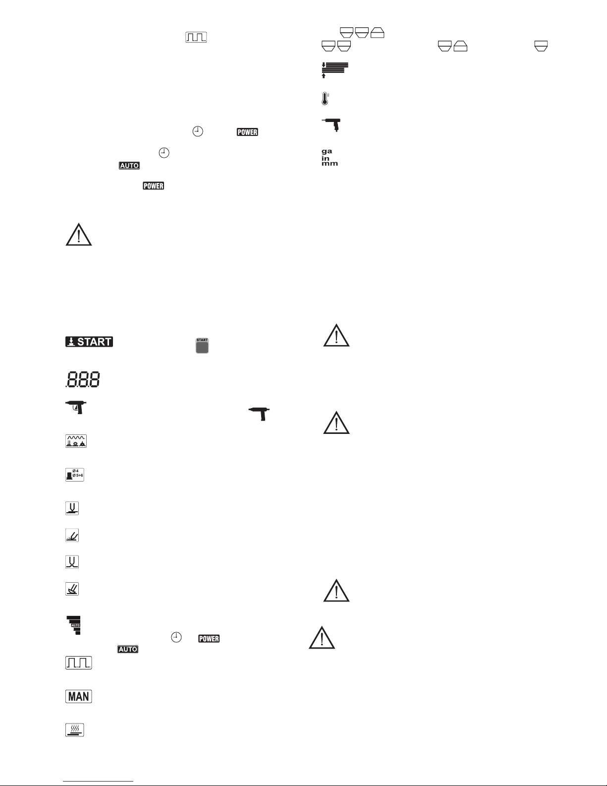
- 12 -
b) FUNZIONE “MODE”:
seleziona la puntatura ad “impulsi” (attivabile solo con le pinze
pneumatiche)oppureselezional’utensiledellostudder(g.C-8a/8fattivabile
solo con la pistola studder).
c) SCELTA DELL’UNITA’ di MISURA:
mantenendo premuto per 3 secondi il tasto è possibile impostare l’unità di
misura dello spessore della lamiera in “millimetri” [mm], “gauge” [ga] oppure
inch [in].
2-3.-/+Tastiadoppiafunzione
a) FUNZIONE SPESSORE della LAMIERA:
premendo il tasto [+] si incrementa lo spessore della lamiera, premendo il tasto
[-] si diminuisce.
b) FUNZIONE SELEZIONE LIVELLO TIME o POWER :
mantenendo premuto il tasto [-] per 3 secondi è possibile incrementare o
diminuire il tempo di saldatura rispetto al valore impostato automaticamente
dalla macchina ;
mantenendo premuto il tasto [+] per 3 secondi è possibile incrementare o
diminuire la potenza di saldatura rispetto al valore impostato
automaticamente dalla macchina;
NOTA: la programmazione della potenza di puntatura permette di modicare
il valore della corrente programmato in fabbrica (5kA), adatto per una potenza
installata di 10 kW .
IMPORTANTE: La TAB. 1 fornisce la corrispondenza tra la
correnteselezionataelapotenzaminimadirete,chedev’esseredisponibile
nel luogo d’installazione (potenza installata), per evitare la possibilità
d’interventointempestivodellaprotezionedilinea.
E’ consigliabile eseguire l’adeguamento della programmazione sia nel
casoilvaloredi“default”risultiinsufcienteperun’ottimaesecuzionedel
puntoconlospessoreselezionato(lospessorecorrispondentelampeggia),
oppure,quandolapotenzainstallataècompatibile,selezionandoilvaloredi
7kAegarantendocosìmaggioresicurezzaoperativaintutteleapplicazioni.
Laprogrammazioneconvaloridicorrenteinferiorilimita,diconseguenza,
lospessoremassimosaldabile.
4. DisplayLCD
5.
Segnala che è necessario premere il tasto per abilitare la macchina alla
saldatura.
6.
Visualizza lo spessore della lamiera ed eventuali codici di allarme.
7.
Si attiva collegando la pistola Studder con grilletto oppure senza (versione
attivabile a contatto).
8a.
Indica la puntatura di spine, ribattini, rondelle, rondelle speciali con appositi
elettrodi.
8b.
Indica la puntatura di viti diametro 4÷6, e ribattini diametro 5 con apposito
elettrodo.
8c.
Indica la saldatura a punto singolo con apposito elettrodo.
8d.
Indica il rinvenimento delle lamiere con l’elettrodo al carbone.
8e.
Indica la ricalcatura delle lamiere con apposito elettrodo.
8f.
Indica la puntatura intermittente per la rappezzatura sulle lamiere con apposito
elettrodo.
9.
Indica il livello del tempo di saldatura o del rispetto al valore impostato
automaticamente .
10.
Indica che la funzione della puntatura ad impulsi è stata attivata (solo per pinze
pneumatiche).
11.
Indica che si sta utilizzando una pinza ad azionamento “manuale” e non
“pneumatico”.
12.
Indica che la pinza in uso è energizzata.
13-14-15.
indicano pinza doppio punto, indicano pinza ad “X”, si
attiva con la pistola Studder.
16.
Rappresenta lo spessore della lamiera da saldare.
17.
Indica che la macchina è in protezione termostatica.
18.
Indica che si sta utilizzando la pistola termica a graffe per la saldatura di parti in
plastica.
19.
Indica l’unità di misura dello spessore della lamiera.
4.2.2Grupporegolatoredipressioneemanometro(g.B-8)
Permette di regolare la pressione esercitata agli elettrodi della pinza pneumatica
agendosullamanopoladiregolazioneedimodicareilussodiariadiraffreddamento
delle pinze che lo prevedono. Si consiglia di impostare la pressione al massimo senza
superare8bar.
4.3FUNZIONIDISICUREZZAEDINTERBLOCCO
4.3.1Protezionieallarmi(TAB.2)
a) Protezione termica:
Interviene nel caso di sovratemperatura della puntatrice causata dalla mancanza
o portata insufciente del uido di raffreddamento oppure da un ciclo di lavoro
superiore al limite ammesso.
L’interventoèsegnalatodall’accensionedell’iconasuldisplay(g.C-17)econ:
AL1 = allarme termico macchina.
AL2 = allarme termico pinza, studder.
EFFETTO: blocco movimentazione, apertura elettrodi (cilindro allo scarico); blocco
della corrente (saldatura inibita).
RIPRISTINO: manuale (azione sul pulsante “START” dopo il rientro nei limiti di
temperatura ammessi - spegnimento dell’icona).
b) Interruttore generale:
- Posizione “O” = aperto lucchettabile (vedi capitolo 1).
ATTENZIONE! In posizione ”O” i morsetti interni L1+L2(N) di
collegamentocavodialimentazionesonointensione.
- Posizione “ I ” = chiuso: puntatrice alimentata ma non in funzione (STAND BY - si
richiede di premere il pulsante “START”).
- Funzione emergenza
Con puntatrice in funzione l’apertura (pos. “ I ”=>pos “O” ) ne determina l’arresto
in condizioni di sicurezza:
- corrente inibita;
- apertura degli elettrodi (cilindro allo scarico);
- riavvio automatico inibito.
ATTENZIONE! VERIFICARE PERIODICAMENTE IL CORRETTO
FUNZIONAMENTODELL’ARRESTOINSICUREZZA.
c) Sicurezza gruppo di raffreddamento (versione AQUA)
Interviene in caso di mancanza o caduta di pressione dell’acqua di raffreddamento;
L’intervento è segnalato sul display con AL 9 = allarme mancanza acqua.
EFFETTO: blocco movimentazione, apertura elettrodi (cilindro allo scarico); blocco
della corrente (saldatura inibita).
RIPRISTINO: rabboccare il liquido di raffreddamento quindi spegnere ed accendere
la macchina (vedi anche Par. 5.6 “predisposizione del gruppo di raffreddamento”).
d) Protezione sovra e sotto tensione
L’intervento è segnalato sul display con AL 3 = allarme sovratensione e con AL 4 =
allarme sottotensione.
EFFETTO: blocco movimentazione, apertura elettrodi (cilindro allo scarico); blocco
della corrente (saldatura inibita).
RIPRISTINO: manuale (azione sul pulsante “START”).
e) Pulsante “START” (Fig. C-5).
È necessario il suo azionamento per poter comandare l’operazione di saldatura in
ciascuna delle seguenti condizioni:
- ad ogni chiusura dell’interruttore generale (pos “O”=>pos “ I ”);
- dopo ogni intervento dei dispositivi di sicurezza/ protezione;
- dopo il ritorno dell’alimentazione di energia (elettrica ed aria compressa)
precedentemente interrotta per sezionamento a monte o avaria;
ATTENZIONE! VERIFICARE PERIODICAMENTE IL CORRETTO
FUNZIONAMENTO DELL’AVVIO IN SICUREZZA
5.INSTALLAZIONE
ATTENZIONE!ESEGUIRETUTTELEOPERAZIONIDIINSTALLAZIONE
ED ALLACCIAMENTI ELETTRICI E PNEUMATICI CON LA PUNTATRICE
RIGOROSAMENTESPENTAESCOLLEGATADALLARETEDIALIMENTAZIONE.
GLI ALLACCIAMENTI ELETTRICI E PNEUMATICI DEVONO ESSERE ESEGUITI
ESCLUSIVAMENTEDAPERSONALEESPERTOOQUALIFICATO.
5.1ALLESTIMENTO
Disimballare la puntatrice, eseguire il montaggio della parti staccate contenute
nell’imballo come indicato in questo capitolo (Fig.D).
5.2MODALITÀDISOLLEVAMENTO(Fig.E).
Il sollevamento della puntatrice dev’essere eseguito con doppia fune e ganci
opportunamente dimensionati per il peso della macchina, utilizzando gli appositi anelli
M8.
E’ assolutamente vietato imbragare la puntatrice con modalità diverse da quelle
indicate.

- 13 -
5.3UBICAZIONE
Riservareallazonad’installazioneunaareasufcientementeampiaeprivadiostacoli
atta a garantire l’accessibilità al pannello comandi all’interruttore generale e all’area di
lavoro in piena sicurezza.
Accertarsi che non vi siano ostacoli in corrispondenza delle aperture di ingresso o
uscitadell’ariadiraffreddamento,vericandochenonpossanoveniraspiratepolveri
conduttive, vapori corrosivi, umidità etc.
Posizionarelapuntatricesuunasuperciepianadimaterialeomogeneoecompatto
adatta a sopportarne il peso (vedi “dati tecnici”) per evitare il pericolo di ribaltamento
o spostamenti pericolosi.
5.4COLLEGAMENTOALLARETE
5.4.1Avvertenze
Prima di effettuare qualsiasi collegamento elettrico, vericare che i dati di targa
della puntatrice corrispondano alla tensione e frequenza di rete disponibili nel luogo
d’installazione.
La puntatrice deve essere collegata esclusivamente ad un sistema di alimentazione
con conduttore di neutro collegato a terra.
Per garantire la protezione contro il contatto indiretto usare interruttori differenziali
del tipo:
- Tipo A ( ) per macchine monofasi;
- Tipo B ( ) per macchine trifasi.
- La puntatrice non rientra nei requisiti della norma IEC/EN 61000-3-12.
Se essa viene collegata a una rete di alimentazione pubblica, è responsabilità
dell’installatoreodell’utilizzatorevericarechelasaldatricepossaessereconnessa
(se necessario, consultare il gestore della rete di distribuzione).
5.4.2Spinaepresadirete
Collegare al cavo di alimentazione una spina normalizzata ( 3P + T: vengono utilizzati
solo 2 poli: collegamento INTERFASICO!) di portata adeguata e predisporre una presa
di rete protetta da fusibili o da interruttore automatico magnetotermico ; l’apposito
terminale di terra dev’essere collegato al conduttore di terra (giallo-verde)della llinea
di alimentazione.
La portata e la caratteristica d’intervento dei fusibili e dell’interruttore magnetotermico
sono riportate nel paragrafo “DATI TECNICI”.
Qualora vengano installate più puntatrici distribuire l’alimentazione ciclicamente tra le
tre fasi in modo tale da realizzare un carico più equilibrato; esempio:
puntatrice 1: alimentazione L1-L2;
puntatrice 2: alimentazione L2-L3;
puntatrice 3: alimentazione L3-L1.
ATTENZIONE! L’inosservanza delle regole sopraesposte rende
inefcace il sistema di sicurezza previsto dal costruttore (classe I) con
conseguentigravirischiperlepersone(es.shockelettrico)eperlecose(es.
incendio).
5.5COLLEGAMENTOPNEUMATICO
- Predisporreunalineaariacompressaconpressionediesercizioad8bar.
- Montaresulgruppoltroriduttoreunodeiraccordiariacompressaadisposizione
per adeguarsi agli attacchi disponibili nel luogo d’installazione.
5.6PREDISPOSIZIONEDELGRUPPODIRAFFREDDAMENTO(VersioneAQUA)
ATTENZIONE!Leoperazionidiriempimentodevonoessereeseguite
conl’apparecchiaturaspentaescollegatadallaretedialimentazione.
Evitarediusareliquidiantigeloelettricamenteconduttivi.
Usaresoloacquademineralizzata.
- Aprire la valvola di scarico (FIG. B-11).
- Effettuare il riempimento del serbatoio con acqua demineralizzata attraverso il
bocchettone(Fig.B-9):capacità delserbatoio=8l;porreattenzioneadevitare
ognieccessivafuoriuscitad’acquaaneriempimento.
- Chiudere il tappo del serbatoio.
- Chiudere la valvola di scarico.
5.7COLLEGAMENTOPINZAPNEUMATICA(Fig.F)
- Collegare le spine DINSE nelle apposite prese.
ATTENZIONE! Le “dinse” dei cavi si connettono alle prese del
pannellotramiteunarotazioneoraria:vericarechelatorsionedeicavinon
tendaadallentarelaconnessione;intalcasoruotarele“dinse”deicaviin
sensoantiorarioprimadiinserirleebloccarlenelpannello.
- Collegare le due spine dell’aria nelle apposite prese della puntatrice: spina piccola
(aria raffreddamento); spina grande (aria comando pistola pneumatica).
- Solo per la versione AQUA, collegare i tubi dell’acqua della pinza alle apposite
prese rapide della macchina rispettando i colori: tubo blu su presa blu, tubo rosso
su presa rossa.
- Inserire il connettore del cavo comando nella apposita presa 14 pin.
5.8 COLLEGAMENTO PINZA MANUALE E PISTOLA STUDDER CON CAVO DI
MASSA(FIG.G)
- Collegare le spine DINSE nelle apposite prese: solo per lo studder collegare la
pistolaelamassaallerelativedinse,comeriportatosullaserigraadellamacchina.
- Inserire il connettore del cavo comando nella apposita presa.
I collegamenti delle prese aria dell’aria compressa non sono necessari.
5.9COLLEGAMENTOPINZADOPPIOPUNTO
- Procedere nello stesso modo della pinza pneumatica utilizzando solo la spina
dell’aria di raffreddamento.
6.SALDATURA(Puntatura)
6.1OPERAZIONIPRELIMINARI
Prima di eseguire qualsiasi operazione di puntatura, sono necessarie una serie
di veriche e regolazioni, da eseguire con interruttore generale in posizione ”O” e
lucchetto chiuso.
- Controllare che l’allacciamento elettrico sia eseguito correttamente secondo le
istruzioni precedenti.
- Vericare l’allacciamento aria compressa; eseguire il collegamento del tubo di
alimentazione alla rete pneumatica, regolare la pressione tramite la manopola del
riduttoresinoaleggeresulmanometrounvalorecompresotra4e8bar(60-120
psi) in funzione dello spessore della lamiera da puntare.
- Interporre tra gli elettrodi uno spessore equivalente allo spessore delle lamiere;
vericarecheibracci,avvicinatimanualmente,risultinoparallelieglielettrodiin
asse (punte coincidenti).
Effettuare la regolazione, se necessario, allentando le viti di bloccaggio dei bracci
chepossonoessereruotatiospostatiinentrambiisensilungoilloroasse;ane
regolazione serrare accuratamente le viti di bloccaggio.
- La regolazione della corsa di lavoro si effettua agendo sugli elettrodi. Va sempre
tenuto presente che è necessaria una corsa maggiore di 6-8 mm rispetto la
posizione di puntatura in modo da esercitare sul pezzo la forza prevista.
La FIG. I fornisce una regolazione “standard” della posizione degli elettrodi con
pinza a riposo.
- Utilizzando la pinza manuale, tenere presente che la regolazione della forza
esercitata dagli elettrodi in fase di puntatura si ottiene agendo sul dado zigrinato
(FIG. L); avvitare in senso orario (destrorso) per aumentare la forza proporzionale
all’aumentare dello spessore delle lamiere, scegliendo tuttavia regolazioni che
permettono la chiusura della pinza (e relativo azionamento del microswitch)
esercitando uno sforzo molto limitato. Il corretto posizionamento di bracci ed
elettrodi è analogo a quanto previsto per la pinza pneumatica.
6.2REGOLAZIONEDEIPARAMETRI(inpuntatura)
I parametri che intervengono a determinare il diametro (sezione) e la tenuta meccanica
del punto sono:
- Forza esercitata dagli elettrodi.
- Corrente di puntatura.
- Tempo di puntatura.
Inmancanzadiesperienzaspecicaèopportunoeseguirealcuneprovedipuntatura
utilizzando spessori di lamiera della stessa qualità e spessore del lavoro da eseguire.
Adeguare la forza degli elettrodi agendo sul regolatore di pressione come indicato in
6.1 scegliendo valori medio-alti.
I parametri corrente e tempo di puntatura vengono regolati automaticamente
selezionando lo spessore delle lamiere da saldare con i tasti (icone +/ -). Eventuali
aggiustamenti del tempo punto rispetto al valore standard (DEFAULT) si possono
eseguire,entrolimitipressati,agendosultasto(iconag.C-2).
Inserire la pulsazione dovendopuntarelamieredispessore0.8÷1.2mmad
alto limite di snervamento.
Il periodo di pulsazione è automatico, non necessita regolazione.
IMPORTANTE:Selospessoreselezionato“lampeggia”signica chela correntedi
puntatura di default ,oinizialmenteprogrammata,èinsufcientepereseguire
il punto in modo soddifacente; compatibilmente con la potenza disponibile nel luogo
d’installazione riprogrammare la puntatrice alla massima corrente (vedi paragrafo
4.2.1): correnti di puntatura elevate abbinate a tempi ridotti conferiscono caratteristiche
migliori al punto.
Si considera corretta l’esecuzione del punto quando sottoponendo un provino a prova
di trazione, si provoca l’estrazione del nocciolo del punto di saldatura da una delle
due lamiere.
6.3PROCEDIMENTO
6.3.1PINZAPNEUMATICA
- Il tempo di accostaggio (SQUEEZE TIME) è automatico, il valore varia in funzione
dello spessore di lamiera selezionato.
- Appoggiareunelettrodosullasuperciediunadelleduelamieredapuntare.
- premere il pulsante sull’impugnatura della pinza ottenendo:
a) Chiusura delle lamiere tra gli elettrodi con la forza preregolata (azionamento
cilindro).
b) Passaggio della corrente di saldatura pressata per il tempo pressato
segnalati dall’accensione e spegnimento dell’icona .
- Rilasciare il pulsante dopo qualche istante dallo spegnimento dell’icona (ne
saldatura); questo ritardo (mantenimento) conferisce migliori caratteristiche
meccaniche al punto.
6.3.2PINZEMANUALI
- Appoggiare l’elettrodo inferiore sulle lamiere da puntare.
- Azionarelalevasuperioredellapinzaanecorsa,ottenendo:
a) Chiusura delle lamiere tra gli elettrodi con la forza preregolata.
b) Passaggio della corrente di saldatura pressata per il tempo pressato
segnalati dall’accensione e spegnimento dell’icona .
- Rilasciare la leva della pinza dopo qualche istante dallo spegnimento dell’icona
(nesaldatura); questoritardo(mantenimento)conferiscemiglioricaratteristiche
meccaniche al punto.
6.3.3PISTOLASTUDDER
ATTENZIONE!
- Perssareosmontaregliaccessoridalmandrinodellapistolautilizzaredue
chiavisseesagonaliinmododaimpedirelarotazionedelmandrinostesso.
- Nelcasodioperazionesuporteocofanicollegareobbligatoriamentelabarra
dimassasuquestepartiondeimpedireilpassaggiodicorrenteattraversole
cerniere,ecomunqueinprossimitàdellazonadapuntare(lunghipercorsidi
correnteriduconol’efcienzadelpunto).
6.3.4Collegamentodelcavodimassa
a) Portare a nudo la lamiera il più vicino possibile al punto in cui s’intende operare,
perunasuperciecorrispondenteallasuperciedicontattodellabarradimassa.
b1) FissarelabarradirameallasuperciedellalamierausufruendodiunaPINZA
ARTICOLATA (modello per saldature).
In alternativa alla modalità “b1” (difcoltà di attuazione pratica) adottate la
soluzione:
b2) Puntareunarondellasullasuperciedellalamieraprecedentementepreparata;
far passare la rondella attraverso la feritoia della barra di rame e bloccarla con
l’apposito morsetto in dotazione.
Puntaturarondellaperssaggioterminaledimassa
Montare nel mandrino della pistola l’apposito elettrodo (POS.9, Fig. M) e inserirvi la
rondella (POS.13, Fig. M).
Appoggiare la rondella nella zona scelta. Mettere in contatto, sulla stessa zona,
il terminale di massa; premere il pulsante della pistola attuando la saldatura della
rondellasullaqualeeseguireilssaggiocomedescrittoprecedentemente.
Puntaturaviti,rosette,chiodi,rivetti
Dotare la pistola dell’elettrodo adatto inserirvi l’elemento da puntare ed appogiarlo alla

- 14 -
lamiera sul punto desiderato; premere il pulsante della pistola: rilasciare il pulsante
solo dopo trascorso il tempo impostato.
Puntatura lamiere da un solo lato
Montare nel mandrino pistola l’elettrodo previsto (POS.6, Fig. M) premendo sulla
superciedapuntare.Azionareilpulsantedellapistola,rilasciareilpulsantesolodopo
trascorso il tempo impostato.
ATTENZIONE!
Massimo spessore della lamiera puntabile, da un solo lato: 1+1 mm . Non è
ammessaquestapuntaturasustruttureportantidellacarrozzeria.
Per ottenere risultati corretti nella puntatura delle lamiere è necessario adottare alcune
precauzioni fondamentali:
1 - Una connessione di massa impeccabile.
2 - Le due parti da puntare devono essere messe a nudo da eventuali vernici,
grasso, olio.
3 - Le parti da puntare dovranno essere a contatto l’una con l’altra, senza intraferro,
al bisogno pressare con un utensile, non con la pistola. Una pressione troppo
forte porta a cattivi risultati.
4 - Lo spessore del pezzo superiore non deve superare 1 mm.
5 - La punta dell’elettrodo deve possedere un diametro di 2.5 mm.
6 - Stringerebeneildadochebloccal’elettrodo,vericarecheiconnettorideicavidi
saldatura siano bloccati.
7 - Quando si punta, appoggiare l’elettrodo esercitando una leggera pressione
(3÷4 kg). Premere il pulsante e far trascorrere il tempo di puntatura, solo allora
allontanarsi con la pistola.
8 - Nonallontanarsimaipiùdi30cmdalpuntodissaggiodallamassa.
Puntaturaetrazionecontemporaneadirondellespeciali
Questa funzione si esegue montando e serrando a fondo il mandrino (POS.4, Fig.
M) sul corpo dell’estrattore (POS.1, Fig. M), agganciare e serrare a fondo l’altro
terminale dell’estrattore sulla pistola. Inserire la rondella speciale (POS.14, Fig. M)
nel mandrino (POS.4, Fig. M), bloccandola con l’apposita vite (Fig. M). Puntarla nella
zona interessata regolando la puntatrice come per la puntatura delle rondelle ed
iniziare la trazione.
Al termine, ruotare l’estrattore di 90° per staccare la rondella, che può essere ripuntata
in una nuova posizione.
Riscaldamento e ricalco lamiere
In questa modalità operativa il TIMER è disattivato.
La durata delle operazioni è quindi manuale essendo determinata dal tempo in cui si
tiene premuto il pulsante della pistola.
L’intensità della corrente è regolata automaticamente in funzione dello spessore della
lamiera scelto.
Montare l’elettrodo di carbone (POS.12, FIG. M) nel mandrino della pistola bloccandolo
con la ghiera. Toccare con la punta del carbone la zona precedentemente portata
a nudo e spingere il pulsante della pistola. Agire dall’esterno verso l’interno con un
movimento circolare così da scaldare la lamiera che, incrudendosi, ritornerà nella sua
posizione originale.
Onde evitare che la lamiera rinvenga troppo, trattare piccole zone e subito dopo
l’operazione passare uno straccio umido, così da raffreddare la parte trattata.
Ricalco lamiere
In questa posizione operando con l’apposito elettrodo si possono appiattire lamiere
che hanno subito delle deformazioni localizzate.
Puntatura intermittente
Questa funzione è adatta alla puntatura di piccoli rettangoli di lamiera così da coprire
fori dovuti alla ruggine o ad altre cause.
Mettere l’apposito elettrodo (POS.5, Fig. M) sul mandrino, stringere accuratamente la
ghieradissaggio.Portareanudolazonainteressataedassicurarsicheilpezzodi
lamiera che si vuol puntare sia pulito ed esente da grasso o vernice.
Posizionare il pezzo ed appoggiarvi l’elettrodo, quindi spingere il pulsante della pistola
tenendo sempre premuto il pulsante, avanzare ritmicamente seguendo gli intervalli di
lavoro/riposo dati dalla puntatrice.
N.B.: Durante il lavoro esercitare una leggera pressione (3÷4 kg), operare seguendo
una linea ideale a 2÷3 mm dal bordo del nuovo pezzo da saldare.
Per avere buoni risultati:
1 - Nonallontanarsipiùdi30cmdalpuntodissaggiodellamassa.
2 - Adoperarelamieredicoperturadispessoremassimo0.8mmmegliosed’acciaio
inossidabile.
3 - Ritmare il movimento di avanzamento con la cadenza dettata dalla puntatrice.
Avanzare nel momento di pausa, fermarsi nel momento della puntatura.
Utilizzodell’estrattoreindotazione(POS.1,Fig.M)
Aggancioetrazionerondelle
Questa funzione si esegue montando e serrando il mandrino (POS.3, Fig. M) sul corpo
dell’elettrodo (POS.1, Fig. M). Agganciare la rondella (POS.13, Fig. M), puntata come
descritto precedentemente, e iniziare la trazione. Al termine ruotare l’estrattore di 90°
per staccare la rondella.
Aggancioetrazionespine
Questa funzione si esegue montando e serrando il mandrino (POS.2, Fig. M) sul corpo
dell’elettrodo (POS.1, Fig. M). Far entrare la spina (POS.15-16, Fig. M), puntata come
descritto precedentemente nel mandrino (POS.1, Fig. M) tenendo tirato il terminale
stesso verso l’estrattore (POS.2, Fig. M). Ad introduzione ultimata rilasciare il mandrino
ediniziarelatrazione.Alterminetirareilmandrinoversoilmartelloperslarelaspina.
STUDDER TOUCH
Lo studder può essere fornito nella versione priva di pulsante.
La puntatura avviene semplicemente appoggiando l’utensile sul pezzo da saldare che
è collegato al cavo di massa: la macchina dopo qualche istante riconosce il contatto e
avvia automaticamente il punto.
ATTENZIONE:EVITAREDIAPPOGGIARELOSTUDDERSULPEZZO
SENONSIINTENDEAVVIARELASALDATURA!
7.MANUTENZIONE
ATTENZIONE! PRIMA DI ESEGUIRE LE OPERAZIONI DI
MANUTENZIONE, ACCERTARSI CHE LA PUNTATRICE SIA SPENTA E
SCOLLEGATADALLARETEDIALIMENTAZIONE.
Ènecessariobloccarel’interruttoreinposizione“O”collucchettoindotazione.
7.1MANUTENZIONEORDINARIA
LE OPERAZIONI DI MANUTENZIONE ORDINARIA POSSONO ESSERE ESEGUITE
DALL’OPERATORE.
- adeguamento/ripristinodeldiametroedelprolodellapuntadell’elettrodo;
- sostituzione degli elettrodi e dei bracci;
- controllo allineamento degli elettrodi;
- controllo raffreddamento di cavi e pinza;
- scaricodellacondensadalltrod’ingressoariacompressa.
- vericaintegritàdelcavodialimentazionedellapuntatriceedellapinza
SOLOperlaversioneAQUA:
- vericaperiodicadellivellonelserbatoiodell’acquadiraffreddamento.
- vericaperiodicadellatotaleassenzadiperdited’acqua.
7.2MANUTENZIONESTRAORDINARIA
LE OPERAZIONI DI MANUTENZIONE STRAORDINARIA DEVONO ESSERE
ESEGUITE ESCLUSIVAMENTE DA PERSONALE ESPERTO O QUALIFICATO IN
AMBITO ELETTRICO-MECCANICO.
ATTENZIONE!PRIMADIRIMUOVEREIPANNELLIDELLAPUNTATRICE
O DELLA PINZA ED ACCEDERE AL SUO INTERNO ACCERTARSI CHE LA
PUNTATRICE SIA SPENTA E SCOLLEGATA DALLA RETE DI ALIMENTAZIONE
ELETTRICAEPNEUMATICA(sepresente).
Eventuali controlli eseguiti sotto tensione all’interno della puntatrice possono causare
shock elettrico grave originato da contatto diretto con parti in tensione e/o lesioni
dovute al contatto diretto con organi in movimento.
Periodicamente e comunque con frequenza in funzione dell’utilizzo e delle condizioni
ambientali, ispezionare l’interno della puntatrice e della pinza per rimuovere la polvere
e le particelle metalliche depositatesi su trasformatore, modulo diodi, morsettiera
alimentazione, etc, mediante getto d’aria compressa secca (max 5 bar).
Evitare di dirigere il getto d’aria compressa sulle schede elettroniche; provvedere alla
loro eventuale pulizia con una spazzola molto morbida od appropriati solventi.
Con l’occasione:
- Vericare che i cablaggi non presentino danni all’isolamento o connessioni
allentate- ossidate.
- Vericare che le viti di collegamento del secondario del trasformatore alle
barre / trecce di uscita siano ben serrate e non vi siano segni di ossidazione o
surriscaldamento.
7.2.1Interventisulgruppodiraffreddamentoadacqua(soloversioneAQUA)
In caso di:
- eccessiva necessità di ripristinare il livello d’acqua nel serbatorio;
- eccessiva frequenza di intervento allarme 9;
- perdite acqua;
è opportuno procedere con una verica di eventuali problematiche presenti
internamente alla zona gruppo di raffreddamento.
Facendo sempre riferimento alla sezione 7.2 per le attenzioni generali e comunque
dopo aver scollegato la puntatrice dalla rete di alimentazione, procedere con la
rimozione del pannello laterale (FIG.N).
Controllare che non vi siano perdite sia dalle connessioni, sia dalle tubazioni. In caso
di perdita acqua, provvedere alla sostituzione della parte danneggiata. Eliminare
residui di acqua eventualmente persa durante la manutenzione e richiudere il pannello
laterale.
Procedere quindi col ripristino della puntatrice utilizzando le opportune informazioni
indicate nel paragrafo 6 (Puntatura).
8.RICERCAGUASTI
NELL’EVENTUALITA’ DI FUNZIONAMENTO INSODDISFACENTE, E PRIMA
DI ESEGUIRE VERIFICHE PIU’ SISTEMATICHE O RIVOLGERVI AL VOSTRO
CENTRO ASSISTENZA, CONTROLLARE CHE:
- Con interruttore generale della puntatrice chiuso (pos. “ I ”) il display sia accesso;
in caso contrario il difetto risiede nella linea di alimentazione (cavi, presa e spina,
fusibili, eccessiva caduta di tensione, etc).
- Il display non visualizzi segnali di allarme (vedere TAB. 2): cessato l’allarme
premere “START” per riattivare la puntatrice; controllare la corretta circolazione
dell’acqua del uido di raffreddamento ed eventualmente ridurre il rapporto
d’intermittenza del ciclo di lavoro.
- Gli elementi facenti parti del circuito secondario (fusioni portabracci - bracci -
portaelettrodi-cavi)nonsianoinefcientiacausadivitiallentatioossidazioni.
- I parametri di saldatura siano adeguati al lavoro in esecuzione.
- Dopo aver eseguito la manutenzione o la riparazione ripristinare le connessioni
ed i cablaggi com’erano in origine avendo cura che questi non vadano a contatto
con parti in movimento o parti che possano raggiungere temperature elevate.
Fascettare tutti i conduttori com’erano in origine avendo cura di tenere ben separati
tra di loro i collegamenti del primario in alta tensione da quelli secondari in bassa
tensione.
Utilizzare tutte le rondelle e le viti originali per la richiusura della carpenteria.

- 15 -
FRANÇAIS
1.SÉCURITÉGÉNÉRALEPOURLESOUDAGEPARPOINTS...........................15
2.INTRODUCTIONETDESCRIPTIONGÉNÉRALE..............................................16
2.1 INTRODUCTION............................................................................................16
2.2 ACCESSOIRES DE SÉRIE............................................................................16
2.3 ACCESSOIRES SUR DEMANDE ..................................................................16
3.DONNÉESTECHNIQUES...................................................................................16
3.1 PLAQUETTE DES DONNÉES (Fig. A) ..........................................................16
3.2 AUTRES DONNÉES TECHNIQUES .............................................................16
3.2.1 Poste de soudage par points.................................................................16
3.2.2 Groupe de refroidissement (GRA).........................................................16
4.DESCRIPTIONDUPOSTEDESOUDAGEPARPOINT....................................16
4.1 ENSEMBLE DU POSTE DE SOUDAGE PAR POINTS
ET DES COMPOSANTS PRINCIPAUX (Fig. B) ............................................16
4.2 DISPOSITIFS DE CONTRÔLE ET DE RÉGLAGE........................................16
4.2.1 Tableau de contrôle (Fig. C)..................................................................16
4.2.2Grouperégulateurdepressionetmanomètre(g.B-8)........................17
4.3 FONCTIONS DE SÉCURITÉ ET VERROUILLAGE.......................................17
4.3.1 Protections et alarmes (TAB. 2) ............................................................17
5.INSTALLATION....................................................................................................17
5.1 MISE EN PLACE............................................................................................17
5.2 MODALITÉS DE SOULÈVEMENT (Fig. E)....................................................17
5.3 POSITIONNEMENT .......................................................................................17
5.4 BRANCHEMENT AU RÉSEAU ......................................................................18
5.4.1 Avertissements......................................................................................18
5.4.2 Fiche et prise...............................................................................................18
5.5 BRANCHEMENT PNEUMATIQUE ..........................................................18
5.6 PRÉDISPOSITION DU GROUPE DE REFROIDISSEMENT (AQUA)...........18
5.7 BRANCHEMENT DE LA PINCE PNEUMATIQUE (Fig. F).............................18
5.8BRANCHEMENTDELAPINCEMANUELLE
ET PISTOLET STUDDER AVEC CÂBLE DE MASSE (FIG. G) .....................18
5.9 BRANCHEMENT DE LA PINCE DOUBLE POINT.........................................18
6.SOUDAGE(PARPOINTS)..................................................................................18
6.1 OPÉRATIONS PRÉALABLES........................................................................18
6.2 RÉGLAGE DES PARAMÈTRES (en pointage) .............................................18
6.3 PROCÉDÉ......................................................................................................18
6.3.1 PINCE PNEUMATIQUE ........................................................................18
6.3.2 PINCES MANUELLES ..........................................................................18
6.3.3 PISTOLET STUDDER...........................................................................18
6.3.4 Branchement du câble de masse..........................................................18
7.ENTRETIEN.........................................................................................................19
7.1 ENTREIEN ORDINAIRE ................................................................................19
7.2 ENTRETIEN EXTRAORDINAIRE..................................................................19
7.2.1 Interventions sur le groupe de refroidissement à eau
(seulement version AQUA) ...................................................................19
8.RECHERCHEDESAVARIES..............................................................................19
APPAREILLAGES POUR SOUDAGE PAR POINTS À USAGE INDUSTRIEL ET
PROFESSIONNEL.
Note:Dansletextesuivant,onemploieraleterme«postedesoudageparpoints».
1.SÉCURITÉGÉNÉRALEPOURLESOUDAGEPARPOINTS
L’opérateurdoitêtresufsammentinformésurl’utilisationentoutesécuritédu
postedesoudageparpointsetsurlesrisquesliésauxprocédésdusoudagepar
points,auxmesuresdeprotectioncorrespondantesetauxprocéduresd’urgence.
Lepostedesoudageparpoints(seulementdanslesversionsàactionnementavec
cylindrepneumatique)estéquipéd’uninterrupteurgénéralayantdesfonctions
d’arrêtd’urgence,d’unverroupoursonblocageenposition«O»(ouvert).
Lacléduverroupeutêtreremiseexclusivementàunopérateurexpertouinstruit
surlestâchesqui lui sont attribuéesetsurlespossiblesdangers dérivant de
ceprocédédesoudageoud’uneutilisationnégligentedupostedesoudagepar
points.
Enl’absencedel’opérateur,l’interrupteurdoitêtreplacéenposition«O»bloqué
avecleverrouferméetsansclé.
- Exécuterl’installationélectriqueselonlesnormesprévuesetd’aprèsleslois
contrelesaccidents.
- Le poste de soudage par points doit être branché exclusivement à un
systèmed’alimentationavecconducteurdeneutrebranchéàlaterre.
- S’assurerquela prised’alimentationest correctement branchéeàla terre
commeprotection.
- Nepasutiliserdecâblesayantuneisolationdétérioréeoudesconnexions
desserrées.
- Utiliser le poste de soudage par points à une température ambiante de
l’aircompriseentre5°Cet40°Cetàunehumiditérelativede50%pourdes
températures allant jusqu’à 40°C et de 90% pour des températures allant
jusqu’à20°C.
- Ne pas utiliser le poste de soudage par points en milieux humides ou
mouillésousouslapluie.
- Laconnexiondescâblesdesoudageettouteautreinterventiond’entretien
ordinairesurlesbraset/ouélectrodesdoiventêtreexécutéesquandleposte
de soudage par points est éteint et débranché du réseau d’alimentation
électriqueetpneumatique(siprésent).Surlespostesdesoudageparpoints
à actionnement avec cylindre pneumatique, il faut bloquer l’interrupteur
généralenposition«O»avecleverroufourni.
Ilfautrespecterlamêmeprocédurepourlebranchementauréseauhydrique
ouàuneunité de refroidissement àcircuitfermé(postesdesoudage par
pointsavecrefroidissementàeau)etdanstouslescasd’interventionsde
réparation(entretienextraordinaire).
- Sur les postes de soudage par points à actionnement avec cylindre
pneumatique,ilfautbloquerl’interrupteurgénéralenposition«O»avecle
verroufourni.
Ilfautrespecterlamêmeprocédurepourlebranchementauréseauhydrique
ou à une unité de refroidissement à circuit fermé (postes de soudage
par points avec refroidissement à eau) et dans toutes les opérations de
réparation(entretienextraordinaire).
- Ilestinterditd’utiliserl’appareillagedansdesmilieuxcomportantdeszones
classéesàrisqued’explosionàcausedelaprésencedegaz,depoussières
oudebuées.
- Nepassoudersurdesconteneurs,récipientsoutuyauxquicontiennentou
quiontcontenudesproduitsinammablesliquidesougazeux.
- Éviterd’opérersurdesmatériauxpropres avecdes solvantschlorurésou
danslesalentoursdecessubstances.
- Nepassoudersurdesrécipientssouspression.
- Éloignerdelazonedetravailtouteslessubstancesinammables(parex.
bois,papier,chiffons,etc.).
- Laisserrefroidirlemorceauquivientd’êtresoudé!Nepasplacerlemorceau
àproximitédesubstancesinammables.
- S’assurerunrecyclagedel’airadéquatoudesmoyensadaptéspourenlever
lesfuméesdesoudageauxalentoursdesélectrodes;ilfautuneapproche
systématiquepourévaluerleslimitesàl’expositiondesfuméesdesoudage
enfonctiondeleurcomposition,deleurconcentrationetdeladuréedecette
mêmeexposition.
- Toujours protéger les yeux avec des lunettes deprotection prévues à cet
effet.
- Porterdesgantsetdesvêtementsdeprotectionadaptésauxusinagesavec
soudageparpoints.
- Bruit : Si, à cause d’opérations de soudage particulièrement intensives,
on constate un niveau d’exposition quotidienne personnelle (LEP,d) égale
ousupérieureà85db(A), l’utilisationdemoyensdeprotectionindividuelle
adaptésestobligatoire.
- Le passage du courant de pointage provoque l’apparition de champs
électromagnétiques(EMF)localisésdanslesalentoursducircuitdepointage.
Leschampsélectromagnétiquespeuventinterféreraveccertainsappareillages
médicaux(ex.Pacemakers,respirateurs,prothèsesmétalliquesetc.).
Il faut prendre les mesures de protection adaptées à l’égard des personnes
portantcesappareillages.Interdireparexemplel’accèsàl’aired’utilisationdu
postedesoudageparpoints.
Cepostedesoudageparpointsrépondauxstandardstechniquesdeproduit
pour l’utilisation exclusive en milieu industriel à but professionnelle. La
conformitéaux limitesdebaseconcernantl’exposition humaineauxchamps
électromagnétiquesenmilieudomestiquen’estpasassurée.
L’opérateurdoitutiliserlesprocéduressuivantesdefaçonàréduirel’exposition
auxchampsélectromagnétiques:
- Fixer ensemble, le plus près possible, les deux câbles de pointage (si
présents).
- Maintenir la tête et le tronc du corps le plus loin possible du circuit de
pointage.
- Nejamaisenroulerlescâblesdepointage(siprésents)autourducorps.
- Nejamaispointerlecorpsaumilieuducircuitdepointage.Tenirlesdeux
câblesdumêmecôtéducorps.
- Brancherlecâblederetourducourantdepointage(siprésent)aumorceau
àpointerleplusprèspossibledujointenexécution.
- Ne pas pointer près, assis ou appuyé au poste de soudage par points
(distanceminimale:50cm).
- Nepaslaisserd’objetsferromagnétiquesàproximitéducircuitdepointage.
- Distanceminimale:
- d=3cm,f=50cm(Fig.O);
- d=3cm,f=50cm(Fig.P);
- d=30cm(Fig.Q);
- d=20cm(Fig.R)Studder.
- AppareillagedeclasseA:
Cepostedesoudageparpointsrépondauxqualitésessentiellesrequisespar
lestandardtechniquedeproduitpourl’utilisationexclusiveenmilieuindustriel
etàbutprofessionnelle.
La conformité à la compatibilité électromagnétique dans les bâtiments
domestiques et dans ceux qui sont directement branchés à un réseau
d’alimentation à basse tension alimentant les bâtiments pour l’usage
domestiquen’estpasassurée.
UTILISATION PRÉVUE
L’installationaétéconçuepourêtreutiliséeexclusivementdansunecarrosserie
pourlaréparationdesautomobiles:elledoitêtreutiliséepourlepointaged’une
ou de plusieurs tôles en acier à faible contenu de carbone, de forme et de
dimensionsvariantselonl’usinageàexécuter.
RISQUES RÉSIDUELS
RISQUE D’ÉCRASEMENT DES MEMBRES SUPÉRIEURS
NEPASPOSERLESMAINSÀPROXIMITÉDESPARTIESENMOUVEMENT!
Lamodalitédefonctionnementdupostedesoudageparpointsetlavariabilité
pag. pag.
SOMMAIRE

- 16 -
deformeet de dimensions du morceau en usinage empêchent la réalisation
d’une protection intégrée contre le danger d’écrasement des membres
supérieurs:doigt,main,avant-bras.
Lerisquedoitêtreréduitenadoptantlesmesurespréventivesopportunes:
- L’opérateurdoitêtreexpertouinstruitsurleprocédédesoudageparpoints
aveccettetypologied’appareillages.
- Ilfautexécuter une évaluationdurisquepourchaque typologie detravail
à exécuter ; il faut prédisposer des équipements et des caches pouvant
souteniretguiderlemorceauenusinagedefaçonàéloignerlesmainsdela
zonedangereusecorrespondantauxélectrodes.
- Encasd’utilisationd’unpostedesoudageparpointsportable:empoigner
solidementlapinceaveclesdeuxmainsplacéessurlespoignéesprévuesà
ceteffet;toujoursmaintenirlesmainsloindesélectrodes.
- Danstouslescasoùlaconformationdumorceaulepermet,réglerladistance
desélectrodesdefaçonàcequ’ellenedépassepas6mmdecourse.
- Empêcherqueplusieurspersonnesnetravaillentenmême temps avec le
mêmepostedesoudageparpoints.
- Lazonedetravaildoitêtreinterditeauxpersonnesétrangèresauxopérations.
- Nepaslaisserlepostedesoudageparpointssanssurveillance:dansce
cas,ilestobligatoiredeledébrancherduréseaud’alimentation;dansles
postesdesoudagepar pointsàactionnementaveccylindrepneumatique,
porterl’interrupteurgénéralsur«O»etlebloqueravecleverroufourni,la
clédoitêtreextraiteetconservéeparleresponsable.
- Utiliserexclusivementlesélectrodesprévuespourlamachine(voirlistedes
piècesdétachées)sansaltérerlaformedecelles-ci.
- RISQUE DE BRÛLURES
Certainespartiesdupostedesoudageparpoints(électrodes-brasetzones
adjacentes)peuventatteindredestempératuressupérieuresà65°C:ilfaut
doncporterdesvêtementsdeprotectionadéquats.
Laisserrefroidirlemorceauquivientd’êtresoudéavantdeletoucher!
RISQUE DE RENVERSEMENT ET DE CHUTE
- Placerlepostedesoudageparpointssurunesurfacehorizontaleayantune
capacitéadaptéeàsamasse;attacherlepostedesoudageparpointsau
pland’appui(quandcelaestprévudanslasection«INSTALLATION»dece
manuel).Encascontraire,solsinclinésoudéformés,plansd’appuimobiles,
ilexisteundangerderenversement.
- Il est interdit de soulever le poste de soudage par points, sauf cas
expressémentprévudanslasection«INSTALLATION»decemanuel.
- Danslecasd’uneutilisationdemachinessurchariot:débrancherlepostede
soudageparpointsdel’alimentationélectriqueetpneumatique(siprésente)
avantdedéplacerl’unitédansuneautrezonedetravail.Faireattentionaux
obstaclesetauxaspéritésduterrain(parexemplecâblesettuyaux).
- UTILISATION IMPROPRE
Ilestdangereuxd’utiliserlepostedesoudageparpointspourtoutusinage
différentdeceluiprévu(voirUTILISATIONPRÉVUE)
DISPOSITIFS DE SÉCURITÉ ET PROTECTIONS
Lesprotectionsetlespartiesmobilesdel’enveloppedupostedesoudagepar
pointsdoiventêtreenposition,avantdelebrancherauréseaud’alimentation.
ATTENTION!Touteinterventionmanuellesurdespartiesmobilesaccessibles
dupostedesoudageparpoints,parexemple:
- Substitutionouentretiendesélectrodes
- Réglagedelapositiondubrasoudesélectrodes
DOITÊTREEXÉCUTÉEAVECLEPOSTEDESOUDAGEPARPOINTSÉTEINTET
DÉBRANCHÉ DU RÉSEAU D’ALIMENTATION ÉLECTRIQUE ET PNEUMATIQUE
(siprésent).
INTERRUPTEURGÉNÉRALBLOQUÉSUR«O»AVECVERROUFERMÉETCLÉ
EXTRAITEsurlesmodèlesavecactionnementàCYLINDREPNEUMATIQUE).
EMMAGASINAGE
- Placer la machine et ses accessoires (avec ou sans emballage) dans des
locauxfermés.
- L’humiditérelativedel’airnedoitpasêtresupérieureà80%.
- Latempératureambiantedoitêtrecompriseentre-15°Cet45°C.
Pour les machines équipées d’une unité de refroidissement à eau et à une
températureambianteinférieureà0°C:ajouterleliquideantigelprévuouvider
complètementlecircuithydrauliqueetleréservoiràeau.
Toujours utiliser des mesures adéquates pour protéger la machine contre
l’humidité,lasaletéetlacorrosion.
2.INTRODUCTIONETDESCRIPTIONGÉNÉRALE
2.1INTRODUCTION
Installation mobile pour soudage avec résistance (poste de soudage par points) avec
contrôle numérique par microprocesseur. Équipé de prises rapides pour les câbles
de soudage, il facilite l’interchangeabilité immédiate des équipements, ce qui permet
l’exécution de nombreux usinages à chaud et d’usinages par points sur les tôles,
notamment dans les carrosseries et dans des secteurs avec usinages analogues.
Le poste de soudage par points est disponible en deux versions :
- Version refroidie par air, abrégée en « A.F. ».
- Version refroidie par air et eau (pince), abrégée en « AQUA »
Leurs principales caractéristiques sont :
- choix automatique des paramètres de soudage ;
- reconnaissance automatique de l’outil inséré ;
- commande automatique à extinction minutée du refroidissement à air (eau si
présent) ;
- choix du courant de soudage par points optimum en fonction de la puissance de
réseau disponible ;
- limitationdelasurintensitédeligneàl’insertion(contrôlecosφd’insertion);
- Afcheur CL éclairé par l’arrière pour la visualisation des commandes et des
paramètres programmés ;
Le poste de soudage par points peut opérer sur des tôles en fer à bas contenu en
carbone et sur tôles en fer galvanisé.
2.2ACCESSOIRESDESÉRIE
- Pince à actionnement pneumatique avec câbles, refroidie par air (bras de 120 mm
et électrodes standards) : version A.F.
- Pince à actionnement pneumatique avec câbles, refroidie par eau (bras de 120
mm) : version AQUA ;
- Unité intégrée pour le refroidissement à eau à circuit fermé : VERSION AQUA ;
- Grouperéducteurdepression-ltremanomètreavecélectrovanne(alimentationde
l’air comprimé) ;
- Chariot intégré ;
2.3ACCESSOIRESSURDEMANDE
- Paires de bras et électrodes de longueur et / ou forme différentes pour pince
pneumatique refroidie à air / eau (v. liste des pièces détachées).
- Pince à actionnement manuel avec paires de câbles.
- Paires de bras à électrodes de longueur et / ou forme différentes pour pince
manuelle (v. liste des pièces détachées).
- Pince en « C » à actionnement manuel avec câbles.
- Kit Studder complet avec câble de masse séparé et caisse d’accessoires.
- Pince pour double point à refroidissement à air avec câbles.
- Kit Studder sans gâchette, avec câble de masse (il soude au contact sans utiliser
le bouton).
- Kit pied de soutien et déchargeur de poids pour la pince.
3.DONNÉESTECHNIQUES
3.1PLAQUETTEDESDONNÉES(Fig.A)
Les principales données relatives à l’emploi et aux prestations du poste de soudage
parpointssontrésuméessurlaplaquettedescaractéristiquesaveclasignication
suivante.
1 - Nombre de phases et fréquence de la ligne d’alimentation.
2 - Tension d’alimentation.
3 - Puissance de réseau en régime permanent (100%).
4 - Puissance nominale de réseau avec rapport d’intermittence de 50%.
5 - Tension maximale à vide aux électrodes.
6 - Courant maximum avec électrodes en court-circuit.
7 - Courant au secondaire en régime permanent (100%).
8 - Ecartementetlongueurdubras(standard).
9 - Force maximale aux électrodes.
10 - Pression nominale de la source d’air comprimé.
11 - Pression de la source d’air comprimé nécessaire pour obtenir la force maximale
aux électrodes.
12 - Débit de l’eau de refroidissement.
13 - Chute de pression nominale du liquide pour le refroidissement.
14 - Masse de l’appareillage.
15- Symbolesseréférantàlasécuritédontlasignicationestreportéeauchapitre1
“Sécurité générale pour le soudage par points”.
Note:L’exempledeplaquettereportéestindicatifpourlasignicationdessymboles
et des chiffres; les valeurs exactes des données techniques du poste de soudage par
points en votre possession doivent être relevées directement sur la plaquette du poste
de soudage par points.
3.2AUTRESDONNÉESTECHNIQUES
3.2.1Postedesoudageparpoints
Caractéristiquesgénérales
- Tension et fréquence d’alimentation : 400 V (±15%) ~ 2ph-50/60 Hz
ou encore : 230 V (±15%) ~1ph-50/60 Hz
- Classe de protection électrique : I
- Classe d’isolation : H
- Degré de protection de l’enveloppe : IP 20
- Type de refroidissement : A.F. (Air forcé), Eau (version AQUA)
- (*) Encombrement (LxWxH) : 710 x 450 x 910 mm
- (**)Poids : 66kgA.F.,81kgAQUA
Input
- Puissancemaxencourt-circuit(Scc) : 58kVA
- Facteurdepuissanceaumax : 0.8
- Fusibles de réseau retardés : 32 A (400 V)/64 A (230 V)
- Interrupteur automatique de réseau : 32 A @ 400 V (“C”- CEI60947-2)
63 A @ 230 V (“C”- CEI60947-2)
- Câbled’alimentation(L≤4m) : 3x4mm²(400V)-3x6mm²(230V)
Output
- Tension secondaire à vide (U2 d) : 10 V
-
Courant max de soudage par points (I
2
max)
: 7 kA
- Capacité de soudage par points : max 3 + 3 mm
- Rapport intermittence : 1.5% A.F., 3% AQUA
- Force maximale aux électrodes : 150 daN
- Saillance du bras : 120-500 mm
- Réglage du courant de soudage par points : automatique
- Réglage du temps de soudage par points : automatique en fonction
de l’épaisseur de la tôle
et de la pince utilisée.
(*) NOTE : l’encombrement ne comprend pas les câbles et le piquet de soutien.
(**) NOTE : le poids du générateur ne comprend pas la pince et le piquet de soutien.
3.2.2Groupederefroidissement(GRA)
Caractéristiquesgénérales
- Pression maximale (pmax) : 3 bars
- Puissance de refroidissement (P @ 1l/min) : 1 kW
- Capacitéduréservoir : 8l
- Liquide de refroidissement : eau déminéralisée
4.DESCRIPTIONDUPOSTEDESOUDAGEPARPOINT
4.1ENSEMBLEDUPOSTEDESOUDAGEPARPOINTSETDESCOMPOSANTS
PRINCIPAUX(Fig.B)
Surlecôtéantérieur:
1 - Tableau de contrôle ;
2 - Attache pour câbles de la pince (dinse) ;
3 - Prises à branchement rapide pour l’attache des tuyaux d’air ;
4 - Prises à branchement rapide pour l’attache des tuyaux d’eau (version AQUA) ;
5 - Connecteur 14 broches ;
Surlecôtépostérieur:
6 - Interrupteur général ;
7 - Entrée du câble d’alimentation ;
8 - Grouperégulateurdepression,manomètreetltred’entréedel’air;
9 - Bouchon du réservoir du groupe de refroidissement (version AQUA) ;
10 - Niveau de l’eau du GRA (version AQUA) ;
11- Oriced’évacuationdel’airduGRA(versionAQUA).
4.2DISPOSITIFSDECONTRÔLEETDERÉGLAGE
4.2.1Tableaudecontrôle(Fig.C)
1. Toucheàplusieursfonctions
a) FONCTION « START » :
habilite la machine à fonctionner au premier démarrage ou après une situation
d’alarme.
NOTE:L’afcheursignaleàl’opérateur,lecaséchéant,qu’ildoitappuyersur
le bouton « START» pour pouvoir utiliser la machine.
b) FONCTION « MODE » :
sélectionne le soudage par points à « impulsions » (activable

- 17 -
seulementaveclespincespneumatiques)ousélectionnel’outildustudder(g.
C-8a/8factivableseulementaveclepistoletstudder).
c) CHOIX DE L’UNITÉ DE MESURE :
en maintenant la pression pendant 3 secondes sur la touche, il est possible
de programmer l’unité de mesure de l’épaisseur de la tôle en « millimètres »
[mm], “gauge” [ga] ou inch [in].
2-3. -/+Touchesàdoublefonction
a) FONCTION ÉPAISSEUR DE LA TÔLE :
en appuyant sur la touche [+] on incrémente l’épaisseur de la tôle, en appuyant
sur la touche [-] on la diminue.
b) FONCTION SÉLECTION NIVEAU TIME ou POWER :
en maintenant la pression sur la touche [-] pendant 3 secondes, il est possible
d’incrémenter ou de diminuer le temps de soudage par rapport à la valeur
programmée automatiquement par la machine ;
en maintenant la pression sur la touche [+] pendant 3 secondes, il est possible
d’incrémenter ou de diminuer la puissance de soudage par rapport à la
valeur programmée automatiquement par la machine ;
NOTE : la programmation de la puissance de soudage par points permet
demodierla valeur du courantprogramméeenusine(5 kA), adaptéeàune
puissance installée de 10 kW.
IMPORTANT : Le TAB. 1 fournit la correspondance entre le
courant sélectionné et la puissance minimale de réseau, qui doit être
disponible sur le lieu d’installation (puissance installée), pour éviter la
possibilitéd’interventionentempsvouludelaprotectiondeligne.
Ilestconseilléd’exécuterl’adaptationdelaprogrammationquandlavaleur
par«défaut»estinsufsantepouruneexécutionoptimaledupointavec
l’épaisseursélectionnée(l’épaisseurcorrespondanteclignote),ou,quand
lapuissanceinstalléeestcompatible,ensélectionnantlavaleurde7kAce
quigarantitplusdesécuritéopérationnelledanstouteslesapplications.
La programmation avec des valeurs de courant inférieures limite, par
conséquent,l’épaisseurmaximalesoudable.
4. AfcheurCL
5.
Il signale qu’il est nécessaire d’appuyer sur la touche pour habiliter la
machine au soudage.
6.
Ilafchel’épaisseurdelatôleetleséventuelscodesd’alarme.
7.
S’actionne en branchant le pistolet Studder avec gâchette ou sans
(version activable par contact).
8a.
Indique le soudage par points de ches, rivets, rondelles, rondelles spéciales
avec électrodes appropriées.
8b.
Indique le soudage par points de vis d’un diamètre de 4÷6, et de rivets d’un
diamètre de 5 avec électrode appropriée.
8c.
Indique le soudage par point individuel avec électrode appropriée.
8d.
Indique le revenu des tôles avec l’électrode au carbone.
8e.
Indique la déformation par écrasement des tôles avec électrode appropriée.
8f.
Indique le soudage par points intermittent pour le rapiéçage sur les tôles avec
électrode appropriée.
9.
Indique le niveau du temps de soudage ou du par rapport à la valeur
programmée automatiquement .
10.
Indique que la fonction du soudage par points à impulsions a été activée
(seulement pour pinces pneumatiques).
11.
Indique qu’on est en train d’utiliser une pince à actionnement « manuel » et non «
pneumatique ».
12.
Indique que la pince utilisée est sous tension.
13-14-15.
indiquent pince double point, indiquent pince en « X »,
s’active avec le pistolet Studder.
16.
Représente l’épaisseur de la tôle à souder.
17.
Indique que la machine est en protection thermostatique.
18.
Indique qu’on est en train d’utiliser le pistolet thermique à agrafes pour le soudage
de parties en plastique.
19.
Indique l’unité de mesure de l’épaisseur de la tôle.
4.2.2Grouperégulateurdepressionetmanomètre(g.B-8)
Il permet de régler la pression exercée aux électrodes de la pince pneumatique en
agissantsurlapoignéederéglage,etdemodierleuxd’airderefroidissementdes
pinces qui le prévoient. Nous conseillons de programmer la pression au maximum
sansdépasser8bars.
4.3FONCTIONSDESÉCURITÉETVERROUILLAGE
4.3.1Protectionsetalarmes(TAB.2)
a) Protection thermique :
Elle intervient en cas de surchauffe du poste de soudage par points causée par le
manqueoul’insufsancededébitduuidederefroidissementoucauséeparun
cycle de travail supérieur à la limite admise.
L’interventionestsignaléeparl’allumagedel’icônesurl’afcheur(g.C-17)etpar:
AL1 = alarme thermique machine.
AL2 = alarme thermique pince, studder.
EFFET : blocage de la manipulation, ouverture des électrodes (cylindre en
déchargement) ; blocage du courant (soudage inhibé).
RÉTABLISSEMENT : manuel (action sur le bouton « START » après être revenu
dans les limites de température admises - extinction de l’icône).
b) Interrupteur général :
- Position « O » = ouvert pouvant être verrouillé (voir chapitre 1).
ATTENTION!Enposition«O»,lesbornesinternesL1+L2(N)de
branchementducâbled’alimentationsontsoustension.
- Position « I » = fermé : poste de soudage par points alimenté mais pas en
fonction (STAND BY – il faut appuyer sur le bouton « START »).
- Fonction d’arrêt d’urgence
Avec le poste de soudage par points en fonction, l’ouverture (pos. « I »=>pos. «
O ») en détermine l’arrêt en conditions de sécurité :
- courant inhibé ;
- ouverture des électrodes (cylindre en déchargement) ;
- redémarrage automatique inhibé.
ATTENTION!VÉRIFIERPÉRIODIQUEMENTLEFONCTIONNEMENT
CORRECTDEL’ARRÊTENSÉCURITÉ.
c) Sécurité du groupe de refroidissement (version AQUA)
Il intervient en cas de manque ou de chute de pression de l’eau de refroidissement;
L’interventionestsignaléesurl’afcheurparAL9=alarmemanqued’eau.
EFFET : blocage de la manipulation, ouverture des électrodes (cylindre en
déchargement) ; blocage du courant (soudage inhibé).
RÉTABLISSEMENT : rajouter du liquide de refroidissement, puis éteindre et allumer
la machine (voir aussi Par. 5.6 « prédisposition du groupe de refroidissement »).
d) Protection surtension et sous-tension
L’interventionestsignaléesurl’afcheurparAL3=alarmesurtensionetparAL4
= alarme sous-tension.
EFFET : blocage de la manipulation, ouverture des électrodes (cylindre en
déchargement) ; blocage du courant (soudage inhibé).
RÉTABLISSEMENT : manuel (action sur le bouton « START »).
e) Bouton « START » (Fig. C-5).
Son actionnement est nécessaire pour pouvoir commander l’opération de soudage
dans chacune des conditions suivantes :
- à chaque fermeture de l’interrupteur général (pos. « O »=>pos. « I ») ;
- après chaque intervention des dispositifs de sécurité / protection ;
- après le retour de l’alimentation d’énergie (électrique et d’air comprimé)
précédemment interrompue pour cause de sectionnement en amont ou d’avarie ;
ATTENTION!VÉRIFIERPÉRIODIQUEMENTLEBONFONCTIONNEMENT
DUDÉMARRAGEENSÉCURITÉ.
5.INSTALLATION
ATTENTION!EXÉCUTERTOUTESLESOPÉRATIONSD’INSTALLATION
ET LES BRANCHEMENTS ÉLECTRIQUES ET PNEUMATIQUES AVEC LE POSTE
DE SOUDAGE PAR POINTS RIGOUREUSEMENT ÉTEINT ET DÉBRANCHÉ DU
RÉSEAUD’ALIMENTATION.
LES BRANCHEMENTS ÉLECTRIQUES ET PNEUMATIQUES DOIVENT ÊTRE
EXÉCUTÉSEXCLUSIVEMENTPARUNPERSONNELEXPERTOUQUALIFIÉ.
5.1MISEENPLACE
Déballer le poste de soudage par points, exécuter le montage des parties détachées
contenues dans l’emballage comme indiqué dans ce chapitre (Fig.D).
5.2MODALITÉSDESOULÈVEMENT(Fig.E).
Le soulèvement du poste de soudage par points doit être exécuté avec double câble
et crochets opportunément dimensionnés pour le poids de la machine, en utilisant les
anneauxappropriésM8.
Il est absolument interdit d’attacher le poste de soudage par points selon des modalités
différentes de celles indiquées.
5.3POSITIONNEMENT
Réserver à la zone d’installation une aire sufsamment ample et sans obstacles
capable de garantir l’accessibilité au panneau de commandes à l’interrupteur général

-18-
et à l’air de travail en toute sécurité.
S’assurer qu’il n’y a pas d’obstacles en face des ouvertures d’entrée ou de sortie de
l’air de refroidissement et vérier qu’il n’est pas possible d’aspirer des poussières
conductrices, des vapeurs corrosives, de l’humidité, etc.
Positionner le poste de soudage par points sur une surface plane de matériau
homogène et compact pouvant en supporter le poids (voir “données techniques”) pour
éviter le danger de renversement ou des déplacements dangereux.
5.4BRANCHEMENTAURÉSEAU
5.4.1Avertissements
Avantd’effectuertoutbranchementélectrique,vérierquelesdonnéesdeplaquette
du poste de soudage par points correspondent à la tension et à la fréquence de
réseau disponibles sur le lieu de l’installation.
Le poste de soudage par points doit être branché exclusivement à un système
d’alimentation avec conducteur de neutre branché à la terre.
Pour garantir la protection contre le contact indirect, utiliser des interrupteurs
différentiels du type:
- Type A ( ) pour machines monophasées;
- Type B ( ) pour machines triphasées.
- Ce poste de soudage par points ne répond pas aux exigences de la norme IEC/EN
61000-3-12.
En cas de raccordement de ce dernier à un réseau d’alimentation publique,
l’installateuroul’utilisateursonttenusdevérierlapossibilitédebranchementdu
poste de soudage par points (s’adresser si nécessaire au gestionnaire du réseau
de distribution).
5.4.2Ficheetprise
Connecteraucâbled'alimentationunechenormalisée(3P+T:seuls2pôlessont
utilisés : connexion INTERPHASE !) de débit adéquat, et prévoir une prise secteur
protégée par un fusible ou par un interrupteur automatique magnétothermique ; la
borne de terre prévue doit être connectée au conducteur de terre (jaune-vert) de la
ligne d'alimentation.
Le débit et la caractéristique d'intervention des fusibles et de l'interrupteur
magnétothermique sont indiqués dans le paragraphe "INFORMATIONS TECHNIQUES".
En cas d'installation de plusieurs postes de soudage, distribuer l'alimentation
cycliquement entre les trois phases an d'obtenir une charge plus équilibrée, par
exemple :
poste de pointage 1 : alimentation L1-L2 ;
poste de soudage 2 : alimentation L2-L3 ;
poste de soudage 3 : alimentation L3-L1.
ATTENTION ! La non-observation des règles énoncées plus haut
annulelesystèmedesécuritéprévuparlefabricant(classeI)etcomportedes
risques graves pour les personnes (ex. choc électrique) et les appareils (ex.
incendie).
5.5BRANCHEMENTPNEUMATIQUE
- Prédisposeruneligned’aircompriméavecpressiond’exerciceà8bars.
- Montersurlegroupeltreréducteurundesraccordsd’aircompriméàdisposition
pour l’adapter aux attaches disponibles sur le lieu d’installation.
5.6PRÉDISPOSITIONDUGROUPEDEREFROIDISSEMENT(AQUA)
ATTENTION!Lesopérations deremplissagedoiventêtreexécutées
avecl’appareillageéteintetdébranchéduréseaud’alimentation.
Eviterd’utiliserdesliquidesantigelélectriquementconducteurs.
Utiliserseulementdel’eaudéminéralisée.
- Ouvrir la vanne d’écoulement (FIG. B-11).
- Effectuer le remplissage du réservoir avec de l’eau déminéralisée par la tubulure
(Fig.B-9):capacitéduréservoir=8l;faireattentiond’évitertoutefuiteexcessive
d’eauennderemplissage.
- Fermer le bouchon du réservoir.
- Fermer la vanne d’écoulement.
5.7BRANCHEMENTDELAPINCEPNEUMATIQUE(Fig.F)
- BrancherleschesDINSEdanslesprisesprévuesàceteffet.
ATTENTION!Les«dinse»descâblesseconnectentauxprisesdu
tableauparunerotationdanslesensdesaiguillesd’unemontre:vérierque
latorsiondescâblesnedesserrepaslaconnexion;danscecas,tournerles
«dinse»descâblesdanslesenscontrairedesaiguillesd’unemontreavant
delesinséreretdelesbloquerdansletableau.
- Brancherlesdeuxchesdel’airdanslesprisesprévuesàceteffetsurleposte
de soudage par points : petite che (air de refroidissement) ; grande che (air
commande pistolet pneumatique).
- Seulement pour la version AQUA, brancher les tuyaux d’eau de la pince aux prises
à branchement rapide prévues à cet effet sur la machine en respectant les couleurs
: tuyau bleu sur prise bleue, tuyau rouge sur prise rouge.
- Insérer le connecteur du câble de commande dans la prise à 14 broches prévue à
cet effet.
5.8BRANCHEMENTDELAPINCEMANUELLEETPISTOLETSTUDDERAVEC
CÂBLEDEMASSE(FIG.G)
- BrancherleschesDINSEdanslesprisesprévuesàceteffet:seulementpour
le studder, brancher le pistolet et la masse aux dinse concernées, comme sur la
sérigraphie de la machine.
- Insérer le connecteur du câble de commande dans la prise prévue à cet effet.
Les branchements des prises d’air pour l’air comprimé ne sont pas nécessaires.
5.9BRANCHEMENTDELAPINCEDOUBLEPOINT
- Procéder de la même façon que la pince pneumatique en utilisant seulement la
chedel’airderefroidissement.
6.SOUDAGE(PARPOINTS)
6.1OPÉRATIONSPRÉALABLES
Avant de procéder aux opérations de soudage (par points), il est nécessaire
de procéder à une série de contrôles et de réglages devant être effectués avec
l'interrupteur général en position ” O ” et verrouillé .
- Contrôler que le raccordement électrique a été correctement effectué conformément
aux instructions précédentes.
- Contrôler le raccordement d'air comprimé; connecter le tube d'alimentation au
réseau d'alimentation pneumatique, régler la pression au moyen de la poignée du
réducteurjusqu'àafchagesurlemanomètred'unevaleurcompriseentre4et8
bars (60 - 120 psi) en fonction de l'épaisseur de la tôle à traiter.
-
Interposer entre les électrodes une entretoise de même épaisseur que les tôles;
contrôler que les bras approchés manuellement sont parallèles et que les
électrodes sont dans l'axe (pointes en correspondance).
Procéderauréglage,endesserrantsinécessairelesvisdexationdesbrasqui
peuvent être tournés ou déplacés dans les deux directions de leur axe ; une fois le
réglageeffectué,serrerànouveausoigneusementlesvisdexation.
- Le réglage de la course de fonctionnement s'effectue au moyen des électrodes.
Nejamaisoublierqu'unecoursesupérieurede6-8mmparrapportàlapositionde
pointage est nécessaire pour exercer la force nécessaire sur la pièce à souder.
La FIG. I fournit un réglage « standard » de la position des électrodes avec la pince
au repos.
- Au moyen de la pince manuelle, ne pas oublier que le réglage de la force exercée
par les électrodes durant le pointage s'obtient au moyen de l'écrou moleté (FIG.
L) ; serrer dans le sens des aiguilles d'une montre pour augmenter la force en
proportion de l'augmentation de l'épaisseur des tôles, en sélectionnant toutefois
des réglages permettant la fermeture de la pince (et l'actionnement correspondant
du micro-interrupteur) en exerçant un effort très limité. Le positionnement correct
des bras et électrodes est identique aux indications données pour la pince
pneumatique.
6.2RÉGLAGEDESPARAMÈTRES(enpointage)
Les paramètres utiles à la détermination du diamètre (section) et de la tenue
mécanique du point sont les suivants :
- Force exercée par les électrodes.
- Courant de pointage.
- Temps de pointage.
En l'absence d'expérience en la matière, effectuer plusieurs essais de pointage
en utilisant des épaisseurs de tôles de même qualité et épaisseur que le travail à
effectuer.
Adapter la force des électrodes au moyen du régulateur de pression, comme indiqué
au point 6.1, et en sélectionnant des valeurs moyennes-hautes.
Les paramètres courant et temps de soudage par points sont réglés automatiquement
en sélectionnant l’épaisseur des tôles à souder avec les touches (icônes +/ -). Les
éventuels ajustements du temps point par rapport à la valeur standard (DEFAULT)
peuventêtreeffectués,dansles limitespréxées,enagissantsurlatouche(icône
g.C-2).
Insérer la pulsation pourpointerdestôlesd’uneépaisseurde0.8÷1.2mmà
haute limite d’élasticité.
La période de pulsation est automatique, elle n’a pas besoin de réglage.
IMPORTANT:Sil’épaisseursélectionnée«clignote»,celasigniequelecourantde
soudage par points standard ,ouinitialementprogrammé,estinsufsantpour
exécuter le point de façon satisfaisante ; en compatibilité avec la puissance disponible
sur le lieu d’installation, reprogrammer le poste de soudage par points au courant
maximum (voir paragraphe 4.2.1) : des courants de soudage par points élevés
associés à des temps réduits confèrent de meilleures caractéristiques au point.
On considère l’exécution du point comme correcte quand en soumettant une piqûre
au test de traction, on provoque l’extraction du noyau du point de soudage d’une des
deux tôles.
6.3PROCÉDÉ
6.3.1PINCEPNEUMATIQUE
- Le temps d’accostage (SQUEEZE TIME) est automatique, la valeur varie en
fonction de l’épaisseur de tôle sélectionnée.
- Poser une électrode sur la surface d’une des deux tôles à pointer.
- appuyer sur le bouton situé le manche de la pince pour obtenir :
a) Fermeture des tôles entre les électrodes avec la force préréglée (actionnement
cylindre).
b) Passageducourantdesoudagepréxépendantletempspréxésignalépar
l’allumage et l’extinction de l’icône .
- Relâcherleboutonquelquesinstantsaprèsl’extinctiondel’icône(ndesoudage);
ce retard (maintien) confèrent de meilleures caractéristiques mécaniques au point.
6.3.2PINCESMANUELLES
- Poser l’électrode inférieure sur les tôles à pointer.
- Actionnerleleviersupérieurdelapinceenndecourse,pourobtenir:
a) Fermeture des tôles entre les électrodes avec la force préréglée.
b) Passageducourantdesoudagepréxépendantletempspréxésignalépar
l’allumage et l’extinction de l’icône .
- Relâcherlelevierdelapincequelquesinstantsaprèsl’extinctiondel’icône(nde
soudage) ; ce retard (maintien) confère de meilleures caractéristiques mécaniques
au point.
6.3.3PISTOLETSTUDDER
ATTENTION!
- Pourxeroudémonterlesaccessoiresdumandrindupistolet,utiliserdeux
clésxeshexagonalesdefaçonàempêcherlarotationdecemêmemandrin.
- Encasd’opérationsurdesportesoudescapots,brancherobligatoirement
labarredemassesurcespartiespourempêcherlepassagedecourantpar
lescharnières,etquoiqu’ilensoitàproximitédelazoneàpointer(delongs
parcoursdecourantréduisentl’efcacitédupoint).
6.3.4Branchementducâbledemasse
a) Mettre la tôle à nu, le plus près possible du point sur lequel on entend opérer, sur
une surface correspondant à la surface de contact de la barre de masse.
b1) Fixer la barre de cuivre à la surface de la tôle en se servant d’une PINCE
ARTICULÉE (modèle pour soudages).
Enalternativeàlamodalité«b1»(difcultéderéalisationpratique),adopterla
solution :
b2) Pointer une rondelle sur la surface de la tôle précédemment préparée ; faire
passerlarondelleparlassuredelabarreencuivreetlabloqueraveclapince
fournie à cet effet.
Soudageparpointsd’unerondellepourxationduterminaldemasse
Monter l’électrode prévue à cet effet sur le mandrin du pistolet (POS. 9, Fig. M) et y
insérer la rondelle (POS. 13, Fig. M).
Poser la rondelle dans la zone choisie. Mettre le terminal de masse en contact, sur la
même zone ; appuyer sur le bouton du pistolet en réalisant le soudage de la rondelle

- 19 -
surlaquelleexécuterlaxationcommedécritprécédemment.
Soudageparpointsdevis,rondelles,clous,rivets
Équiper le pistolet de l’électrode adaptée, y insérer l’élément à pointer et le poser
contre la tôle sur le point désiré ; appuyer sur le bouton du pistolet : relâcher le bouton
seulement après le temps programmé.
Soudageparpointsdestôlesd’unseulcôté
Monter l’électrode prévue sur le mandrin du pistolet (POS. 6, Fig. M) en appuyant
sur la surface à pointer. Actionner le bouton du pistolet, relâcher le bouton seulement
après le temps programmé.
ATTENTION!
Épaisseurmaximaledelatôlepouvantêtrepointée,d’unseulcôté:1+1mm.
Ce soudage par points n’est pas admis sur des structures portantes de la
carrosserie.
Pour obtenir des résultats corrects dans le soudage par points des tôles, il faut adopter
quelques précautions fondamentales :
1 - Une connexion de masse impeccable.
2 - Les deux parties à pointer doivent être mises à d’éventuelles peintures, graisse,
huile, qui la couvrent.
3 - Les parties à pointer devront être en contact l’une avec l’autre, sans entrefer, au
besoin presser avec un outil, pas avec le pistolet. Une pression trop forte porte à
de mauvais résultats.
4 - L’épaisseur du morceau supérieur ne doit pas dépasser 1 mm.
5 - La pointe de l’électrode doit posséder un diamètre de 2.5 mm.
6 - Bienserrerl’écrouquibloquel’électrode,vérierquelesconnecteursdescâbles
de soudage sont bloqués.
7 - Quand on pointe, poser l’électrode en exerçant une légère pression (3÷4 kg).
Appuyer sur le bouton et laisser passer le temps nécessaire au soudage par
points, et seulement alors éloigner le pistolet.
8 - Nejamaiss’éloignerdelamassedeplusde30cmdupointdexation.
Soudageparpointsettractionsimultanéederondellesspéciales
Cette fonction s’exécute en montant et en serrant à fond le mandrin (POS. 4, Fig. M)
sur le corps de l’extracteur (POS. 1, Fig. M), et en accrochant et serrant à fond l’autre
terminal de l’extracteur sur le pistolet. Insérer la rondelle spéciale (POS. 14, Fig. M)
dans le mandrin (POS. 4, Fig. M), en la bloquant avec la vis prévue à cet effet (Fig. M).
La pointer dans la zone concernée en réglant le poste de soudage par points comme
pour le soudage par points des rondelles et commencer la traction.
Àlan,tournerl’extracteurde90°pourdétacherlarondelle,quipeutêtrerepointée
dans une nouvelle position.
Réchauffementetdéformationparécrasementdestôles
Dans cette modalité opérationnelle, le TIMER est désactivé.
La durée des opérations est donc manuelle car elle est déterminée par le temps
durant lequel on maintient la pression sur le bouton du pistolet.
L’intensité du courant est automatiquement régulée en fonction de l’épaisseur de la
tôle choisie.
Monter l’électrode en carbone (POS. 12, FIG. M) sur le mandrin du pistolet en la
bloquant avec la bague. Toucher de la pointe en carbone la zone précédemment
portée à nu et pousser le bouton du pistolet. Agir de l’extérieur vers l’intérieur avec un
mouvement circulaire de façon à réchauffer la tôle qui, en se durcissant, revient dans
sa position originale.
Pour éviter que la tôle ne revienne trop, traiter de petites zones et tout de suite après
l’opération, passer un chiffon humide, de façon à refroidir la partie traitée.
Déformationparécrasementdestôles
Dans cette position, en opérant avec l’électrode appropriée, on peut aplatir des tôles
qui ont subi des déformations localisées.
Soudage par points intermittent
Cette fonction est adaptée au soudage par points de petits rectangles de tôle pour
couvrir des trous dus à la rouille ou à d’autres causes.
Mettre l’électrode appropriée (POS. 5, Fig. M) sur le mandrin, resserrer soigneusement
labaguedexation.Porterànulazoneconcernéeets’assurerquelemorceaudetôle
que l’on veut pointer est propre et sans graisse ou peinture.
Placer la pièce et y poser l’électrode, puis serrer le bouton du pistolet en maintenant
toujours la pression sur le bouton, avancer en rythme en suivant les intervalles de
travail/repos donnés par le poste de soudage par points.
N.B.: Durant le travail, exercer une légère pression (3÷4 kg), opérer en suivant une
ligne idéale à 2÷3 mm du bord de la nouvelle pièce à souder.
Pour avoir de bons résultats :
1 - Nepass’éloignerdeplusde30cmdupointdexationdelamasse.
2 - Adopterdestôlesdecouvertured’uneépaisseurmaximalede0.8mmsipossible
en acier inoxydable.
3 - Rythmer le mouvement d'avancement à la cadence dictée par le poste de
soudage par points. Avancer au moment de pause, s’arrêter au moment du
soudage par points.
Utilisationdel’extracteurfourni(POS.1,Fig.M)
Accrochageettractiondesrondelles
Cette fonction s’effectue en montant et en serrant le mandrin (POS. 3, Fig. M) sur
le corps de l’électrode (POS. 1, Fig. M). Accrocher la rondelle (POS. 13, Fig. M),
pointéeselonladescriptionprécédente,etcommencerlatraction.Pournir,tourner
l’extracteur de 90° pour détacher la rondelle.
Accrochageettractiondesches
Cette fonction s’effectue en montant et en serrant le mandrin (POS. 2, Fig. M) sur
le corps de l’électrode (POS. 1, Fig. M). Faire entrer la che (POS. 15-16, Fig.
M), pointée selon la description précédente, dans le mandrin (POS. 1, Fig. M) en
maintenant l’extrémité tirée vers l’extracteur (POS. 2, Fig. M). Quand l’introduction est
achevée,relâcherlemandrinetcommencerlatraction.Pournir,tirerlemandrinvers
lemarteaupourextrairelache.
STUDDER TOUCH
Le studder peut être fourni dans la version sans bouton.
Le soudage par points advient simplement en posant l’outil sur la pièce à souder alors
qu’il est branché au câble de masse : après quelques instants, la machine reconnaît
le contact et démarre automatiquement le point.
ATTENTION:ÉVITREDEPOSERLESTUDDERSURLAPIÈCESION
N’ENTENDPASDÉMARRERLESOUDAGE!
7.ENTRETIEN
ATTENTION!AVANTD’EXÉCUTERLESOPÉRATIONSD’ENTRETIEN,
S’ASSURER QUE LE POSTE À SOUDER PAR POINTS EST ÉTEINT ET
DÉBRANCHÉDURÉSEAUD’ALIMENTATION.
Ilestnécessairedebloquerl’interrupteurenposition«O»avecleverroufourni.
7.1ENTREIENORDINAIRE
LES OPÉRATIONS D’ENTRETIEN ORDINAIRE PEUVENT ÊTRE EXÉCUTÉES PAR
L’OPÉRATEUR.
- adaptation/rétablissementdudiamètreetduproldelapointedel’électrode;
- substitution des électrodes et des bras ;
- contrôle de l’alignement des électrodes ;
- contrôle du refroidissement des câbles et de la pince ;
- évacuationdelacondensationdultred’entréedel’aircomprimé.
- véricationdel’intégritéducâbled’alimentationdupostedesoudageparpointset
de la pince
SEULEMENTpourlaversionAQUA:
- véricationpériodiqueduniveaudansleréservoirdel’eauderefroidissement.
- véricationpériodiquedel’absencetotaledefuitesd’eau.
7.2ENTRETIENEXTRAORDINAIRE
LES OPÉRATIONS D’ENTRETIEN EXTRAORDINAIRE DOIVENT ÊTRE
EXÉCUTÉES EXCLUSIVEMENT PAR DU PERSONNEL EXPERT OU QUALIFIÉ
DANSLEDOMAINEÉLECTRIQUEETMÉCANIQUE.
ATTENTION ! AVANT D’ENLEVER LES PANNEAUX DU POSTE DE
SOUDAGE OU DE LA PINCE ET D’ACCÉDER À L’INTÉRIEUR, S’ASSURER
QUE LE POSTE DE SOUDAGE EST ÉTEINT ET DÉBRANCHÉ DU RÉSEAU
D’ALIMENTATIONÉLECTRIQUEETPNEUMATIQUE(s’ilestprésent).
D’éventuels contrôles exécutés sous tension à l’intérieur du poste de soudage par
points peuvent causer une secousse électrique grave provenant d’un contact direct
avec des parties sous tension et/ou des lésions dues au contact direct avec des
organes en mouvement.
Périodiquement et quoi qu’il en soit avec une fréquence en fonction de l’utilisation et
des conditions environnementales, inspecter l’intérieur du poste de soudage et de la
pince pour enlever la poussière et les particules métalliques qui se sont déposées sur
le transformateur, module des diodes, boîte de connexions alimentation, etc., à l’aide
d’un jet d’air comprimé sec (max 5 bars).
Éviter de diriger le jet d’air comprimé sur les cartes électroniques ; pourvoir
éventuellement à les nettoyer avec une brosse très douce ou des solvants appropriés.
À l’occasion :
- Vérierquel’isolationdescâblagesn’estpasendommagéeouleursconnexions
desserrées ou oxydées.
- Vérierquelesvisdebranchementdusecondairedutransformateurauxbarres
/lsdesortiesontbienserréeset qu’il n’y a pas de signes d’oxydation ou de
surchauffe.
7.2.1Interventionssurlegroupederefroidissementàeau(seulementversion
AQUA)
En cas de :
- nécessité excessive de rétablir le niveau d’eau dans le réservoir ;
- fréquence excessive d’intervention de l’alarme 9 ;
- fuites d’eau ;
Ilfautprocéderàunevéricationd’éventuellesproblématiquesprésentesàl’intérieur
de la zone du groupe de refroidissement.
Toujours en référence à la section 7.2 pour les attentions générales et, quoi qu’il en
soit, après avoir débranché le poste de soudage par points du réseau d’alimentation,
procéder à l’extraction du panneau latéral (FIG. N).
Contrôler qu’il n’y a pas de fuites aussi bien en provenance des connexions qu’en
provenance des tuyauteries. En cas de fuite d’eau, pourvoir à la substitution de la
partie endommagée. Eliminer les résidus d’eau qui ont éventuellement coulé durant
l’entretien et refermer le panneau latéral.
Procéder ensuite au rétablissement du poste de soudage par points en utilisant les
informations opportunes indiquées au paragraphe 6 (Pointage).
8.RECHERCHEDESAVARIES
DANS L’ÉVENTUALITÉ D’UN FONCTIONNEMENT INSATISFAISANT, ET AVANT
D’EXÉCUTER DES VÉRIFICATIONS PLUS SYSTÉMATIQUES OU DE S’ADRESSER
AU CENTRE D’ASSISTANCE, CONTRÔLER QUE :
- Avec interrupteur général du poste de soudage par points fermé (pos. « I ») l’écran
est allumé ; en cas contraire le défaut se situe sur la ligne d’alimentation (câbles,
priseetche,fusibles,chutedetensionexcessive,etc.).
- L’écrann’afche pas designauxd’alarme (voirTAB.2): quand l’alarmecesse,
appuyer sur « START » pour réactiver le poste de soudage par points; contrôler la
bonnecirculationdel’eauduuidederefroidissementetéventuellementréduirele
rapport d’intermittence du cycle de travail.
- Les éléments faisant parties du circuit secondaire (fusions porte-bras - bras – porte-
électrodes-câbles)sontinefcacesàcausedevisdesserréesoud’oxydations.
- Les paramètres de soudage sont adaptés au travail en exécution.
- Après avoir exécuté l’opération d’entretien ou la réparation, rétablir les connexions
et les câblages comme ils étaient à l’origine en faisant attention qu’ils n’entrent pas
en contact avec des parties en mouvement ou des parties qui pourraient atteindre
des températures élevées. Lier tous les conducteurs comme ils l’étaient à l’origine
en ayant soin de bien séparer les branchements du primaire à haute tension des
branchements secondaires à basse tension.
Utiliser toutes les rondelles et les vis originales pour refermer la charpente.

- 20 -
ESPAÑOL
1.SEGURIDADGENERALPARALASOLDADORADERESISTENCIA..............20
2.INTRODUCCIÓNYDESCRIPCIÓNGENERAL..................................................21
2.1 INTRODUCCIÓN ...........................................................................................21
2.2 ACCESORIOS DE SERIE..............................................................................21
2.3 ACCESORIOS A PETICIÓN DE LOS INTERESADOS..................................21
3.DATOSTÉCNICOS..............................................................................................21
3.1 PLACA DE DATOS (Figura A) ........................................................................21
3.2 OTROS DATOS TÉCNICOS .........................................................................21
3.2.1 Soldadora por puntos............................................................................21
3.2.2 Grupo de enfriamiento (GRA) ..............................................................21
4.DESCRIPCIÓNDELASOLDADORAPORPUNTOS........................................21
4.1 CONJUNTO DE LA SOLDADORA POR PUNTOS
Y COMPONENTES PRINCIPALES (Figura B) ..............................................21
4.2 DISPOSITIVOS DE CONTROL Y REGULACIÓN..........................................22
4.2.1 Cuadro de control (Fig. C).....................................................................22
4.2.2Gruporeguladordelapresiónymanómetro(g.B-8)..........................22
4.3 FUNCIONES DE SEGURIDAD E INTERBLOQUEO.....................................22
4.3.1 Protecciones y alarmas (TAB. 2)...........................................................22
5.INSTALACIÓN.....................................................................................................22
5.1 PREPARACIÓN..............................................................................................23
5.2 MODALIDAD DE LEVANTAMIENTO (Figura E). ...........................................23
5.3 UBICACIÓN ...................................................................................................23
5.4 CONEXIÓN A LA RED ...................................................................................23
5.4.1 Advertencias..........................................................................................23
5.4.2 Enchufe y toma .....................................................................................23
5.5 CONEXIÓN NEUMÁTICA..............................................................................23
5.6 PREPARACIÓN DEL GRUPO DE ENFRIAMIENTO (AQUA)........................23
5.7 CONEXIÓN DE LA PINZA NEUMÁTICA (Fig. F) ...........................................23
5.8CONEXIÓNDELAPINZAMANUALYDELAPISTOLASTUDDER
CON CABLE DE MASA (FIGURA G) .............................................................23
5.9 CONEXIÓN DE LA PINZA DE PUNTO DOBLE.............................................23
6.SOLDADURA(Soldaduraporpuntos)..............................................................23
6.1 OPERACIONES PRELIMINARES .................................................................23
6.2 REGULACIÓN DE LOS PARÁMETROS (en soldadura por puntos) .............23
6.3 PROCEDIMIENTO .........................................................................................23
6.3.1 PINZA NEUMÁTICA..............................................................................23
6.3.2 PINZAS MANUALES.............................................................................23
6.3.3 PISTOLA STUDDER.............................................................................23
6.3.4 Conexión del cable de masa.................................................................24
7.MANTENIMIENTO...............................................................................................24
7.1 MANTENIMIENTO ORDINARIO....................................................................24
7.2 MANTENIMIENTO EXTRAORDINARIO........................................................24
7.2.1 Intervención en el grupo de refrigeración con agua
(sólo versión AQUA) .............................................................................24
8.BÚSQUEDADEAVERÍAS..................................................................................24
EQUIPOS PARA SOLDADURA DE RESISTENCIA PARA USO INDUSTRIAL Y
PROFESIONAL.
Nota:Eneltextosiguienteseutilizaráeltérmino“soldadoraporpuntos”.
1.SEGURIDADGENERALPARALASOLDADORADERESISTENCIA
Eloperadortienequeconocersucientementeelusosegurodelasoldadora
por puntos y tiene que informarse sobre los riesgos relacionados con los
procedimientosparasoldaduraderesistencia,conlasmedidasdeprotección
correspondientesyconlosprocedimientosdeemergencia.
La soldadora por puntos (solamente en las versiones de accionamiento con
cilindroneumático)sehaequipadoconinterruptorgeneralconfuncionesde
emergencia,equipadoconcandadoparasubloqueoenlaposición“O”(abierto).
Lallavedelcandadopuedeentregarseexclusivamenteaunoperadorexpertoo
instruidoacercadelastareasqueselehanasignadoyacercadelospeligros
posiblesquederivandeesteprocedimientodesoldaduraydelusonegligente
delasoldadoraporpuntos.
En caso de ausencia del operador, el interruptor tiene que ponerse en la
posición“O”,bloqueándoloconuncandadocerradoysinllave.
- Ejecutarlainstalacióneléctricacumpliendolasnormasprevistasylasleyes
enmateriadeprevencióndeaccidentes.
- Lasoldadoraporpuntosdebeconectarseexclusivamenteaunsistemade
alimentaciónconconductordeneutroconectadoatierra.
- Comprobarqueelconectordealimentaciónsehayaconectadocorrectamente
alatierradeprotección.
- Noutilizarcablesconaislamientodeterioradooconconexionesaojadas.
- Utilizar la soldadora por puntos a una temperatura ambiente del aire
incluidaentre5ºCy40ºC,yconhumedadrelativaequivalenteal50%para
temperaturasde40ºC,ydel90%paratemperaturasdehasta20ºC.
- Noutilizarlasoldadoraporpuntosenambienteshúmedosomojadosobajo
lalluvia.
- La conexión de los cables de soldadura y cualquier intervención de
mantenimiento ordinario en los brazos y/o electrodos tienen que ser
realizadasconlasoldadoraporpuntosapagadaydesconectadadelared
de alimentación eléctrica y neumática (si presente). En las soldadoras
porpuntosdeaccionamientoconcilindroneumáticohayquebloquearel
interruptorgeneralenlaposición“O”conelcandadoentregado.
El mismo procedimiento tiene que observarse para la conexión a la red
hídricaoaunaunidadderefrigeraciónconelcircuitocerrado(soldadoras
por puntos refrigeradas con agua) y en cada caso de intervenciones de
reparación(intervencionesdemantenimientoextraordinario).
- En las soldadoras por puntos de accionamiento con cilindro neumático
hayquebloquearelinterruptorgeneralenlaposición“O”conelcandado
entregado.
El mismo procedimiento tiene que observarse para la conexión a la red
hídricaoaunaunidadderefrigeraciónconelcircuitocerrado(soldadoras
por puntos refrigeradas con agua) y en cada caso de intervenciones de
reparación(intervencionesdemantenimientoextraordinario).
- Se prohíbe utilizar el equipo en ambientes con zonas clasicadas como
zonasderiesgodeexplosión,porlapresenciadegases,polvosoneblinas.
- No soldar en contenedores, recipientes o tuberías que contengan o que
hayancontenidoproductosinamableslíquidosogaseosos.
- Evitaroperarenmaterialeslimpioscondisolventescloruradosocercade
estassustancias.
- Nosoldarenrecipientespresurizados.
- Alejar del área de trabajo todas las sustancias inamables (por ejemplo
madera,papel,trapos,etc.).
- ¡Dejarrefrigerarlapiezaqueseacabadesoldar!Nocolocarlapiezacercade
sustanciasinamables.
- Asegurarse un cambio de aire adecuado o con medios adecuados a sacar los
humosdesoldaduracercadeloselectrodos;esnecesariounacercamiento
sistemáticoparalaevaluacióndeloslímitesalaexposicióndeloshumos
desoldaduraenfuncióndesucomposición,concentraciónyduracióndela
exposiciónmisma.
- Siempreprotegerlosojosconlasgafasdeproteccióncorrespondientes.
- Ponerseguantesyropadeprotecciónadecuadosalaselaboracionescon
soldaduraderesistencia.
- Ruido:Siacausadeoperacionesdesoldaduraespecialmenteintensivasse
presentaunniveldeexposicióndiariapersonal(LEP,d)igualomayora85
db(A)esobligatorioelusodemediosdeprotecciónpersonaladecuados.
- El paso de la corriente de soldadura por puntos causa la formación de
campos electromagnéticos (EMF) localizados alrededor del circuito de
soldaduraporpuntos.
Loscamposelectromagnéticospuedeninterferirconalgunosequiposmédicos
(porejemploMarcadordepasos,respiradores,prótesismetálicas,etc.).
Siempre tienen que tomarse medidas de protección adecuadas hacia los
portadoresdeestosequipos.Porejemplo,prohibirelaccesoaláreadeusode
lasoldadoraporpuntos.
Estasoldadoraporpuntoscumplelosestándarestécnicosdeproductopara
elusoexclusivo enambienteindustriala nes profesionales.Nose asegura
elcumplimientodeloslímitesdebaserelativosalaexposiciónhumanaalos
camposelectromagnéticosenambientedoméstico.
El operador tiene que utilizar los procedimientos siguientes, con el n de
reducirlaexposicióndecamposelectromagnéticos:
- Fijarjuntoslomáscercaposiblelosdoscablesdesoldaduraporpuntos(si
presentes).
- Mantenerelcabezalyeltroncodelcuerpolomáslejosposibledelcircuitode
soldaduraporpuntos.
- Nuncaenvolverloscablesdesoldaduraporpuntos(sipresentes)alrededor
delcuerpo.
- No puntar con el cuerpo en medio del circuito de soldadura por puntos.
Manteneramboscablesdelmismoladodelcuerpo.
- Conectar el cable de retorno de la corriente de soldadura por puntos (si
presente)alapiezaquetienequesoldarse,lomáscercaposibledelajunta
queseestáejecutando.
- No soldar cerca, sentados o apoyados en la soldadora por puntos (distancia
mínima:50cm).
- Nodejarobjetosferromagnéticoscercadelcircuitodesoldaduraporpuntos.
- Distanciamínima:
- d=3cm,f=50cm(FiguraO);
- d=3cm,f=50cm(FiguraP);
- d=30cm(FiguraQ);
- d=20cm(FiguraR)Studder.
- EquipodeclaseA:
Esta soldadora por puntos cumple los requisitos del estándar técnico de
productoparaelusoexclusivoenambienteindustrialanesprofesionales.
Noseaseguraelcumplimiento de la compatibilidad electromagnética en los
ediciosdomésticosyenlosediciosdirectamenteconectadosaunaredde
alimentacióndebajatensiónquealimentalosediciosresidenciales.
USO PREVISTO
Lainstalaciónsehadiseñadoparaserutilizadaexclusivamenteencarrocería
paralareparacióndevehículos:tienequeutilizarseparalasoldaduraporpuntos
deunaovariaschapasdeaceroconbajocontenidodecarbono,deformay
dimensionesvariablesenfuncióndelaelaboraciónquehayqueejecutar.
pág. pág.
ÍNDICE
Table of contents
Languages:
Other Suministros Orozco Welding System manuals

Popular Welding System manuals by other brands


WELDING INDUSTRIES
WELDING INDUSTRIES Weldarc 200i DC Operator's manual

SHERMAN-profi
SHERMAN-profi ARC 250C user manual

Miller
Miller Big Blue 400 Eco Pro CC owner's manual

Lincoln Electric
Lincoln Electric COMMANDER 300 IM601-A Operator's manual

Inteco
Inteco Eagle 242 instruction manual

CIGWELD
CIGWELD TRANSTIG 300 AC/DC Service manual


