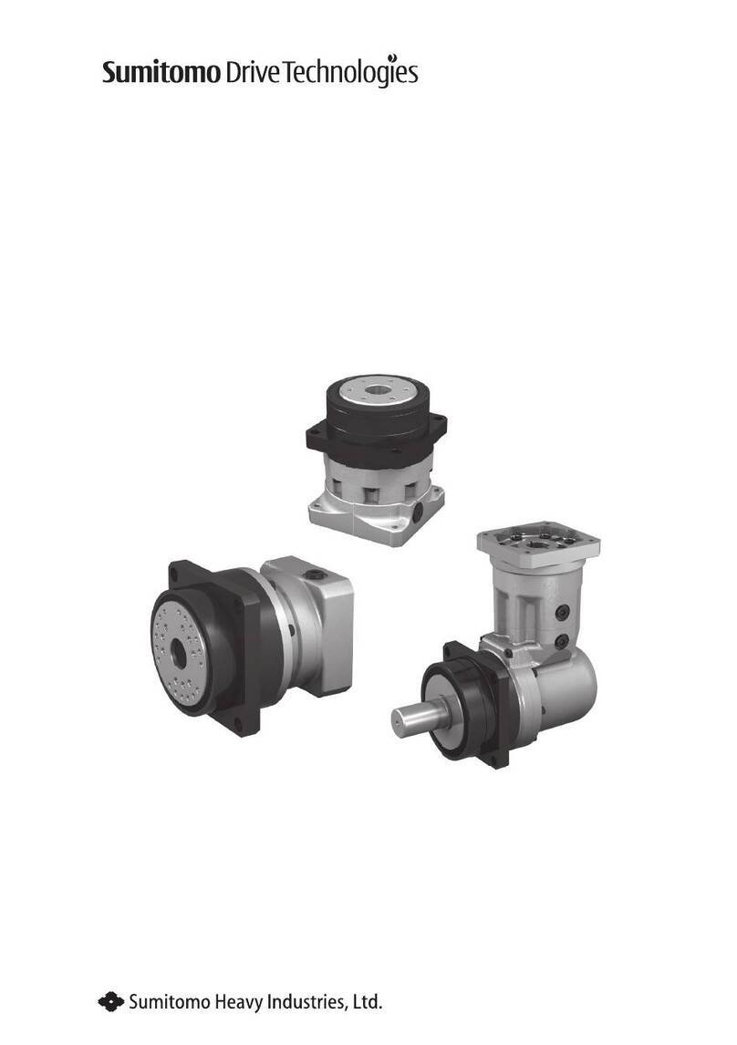
Sumitomo Drive Technologies HYPONIC DRIVE User manual

HYPONICDRIVE®
■Gearmotorsandreducersshouldbehandled,installed,andmaintainedbytrainedtechnicians.
Carefullyreadtheinstructionmanualbeforeuse.
■Acopyofthisinstructionmanualshouldbesenttotheactualuser.
■Thisinstructionmanualshouldberetainedbytheuserforfuturereference.
《CAUTION》
No.NM2201E-6InstructionManual

1
Safety and Other Precautions
Carefully read this maintenance manual and all accompanying documents before use
(installation, operation, maintenance, inspection, etc.). Thoroughly understand the machine,
information about safety, and all precautions for correct operation. Retain this manual for
future reference.
Pay close attention to the "DANGER" and "CAUTION" warnings regarding safety and proper
use.
DANGER
CAUTION
CAUTION
DANGER
Transport, installation, plumbing, wiring, operation, maintenance, and inspections should
be performed by trained technicians; otherwise, electric shock, personal injury, fire, or
damage to the equipment may result.
When using the equipment in conjunction with an explosion proof motor , a technician with
electrical expertise should supervise the transport, installation, plumbing, wiring, operation,
maintenance and inspection of the equipment so as to avoid a potentially nazardous
sitnation that may result in electrical shock, fire, explosion, personal injury and/or damage
to the equipment.
When the unit is to be used in a system for human, transport a protective device should be
installed to minimize chances of accidents that may result in personal injury, death, or
damage to the equipment.
When the unit is to be used for an elevator, install a protective device on the elevator side
to prevent it from falling; otherwise, personal injury, death, or damage to the equipment
may result.
: Improper handling may result in physical damage, serious
personal injury and/or death.
: Improper handling may result in physical damage and/or
personal injury.
Matters described in may lead to serious danger depending on the
situation. Be sure to observe important matters described herein.

2
Specifications
Symbol
Common specifications
Gearmotor
Without Brake
With Brake(Brakemotors)
COMMON
1. Inspection Upon Delivery ……………………………………………………. 3
2. Storage ………………………………………………………………………... 7
3. Transport ……………………………………………………………………… 7
4. Installation ……………………………………………………………………… 8
5. Coupling with Other Machines ……………………………………………… 15
6. Wiring ………………………………………………………………………… 20
7. Operation ……………………………………………………………………… 36
8. Daily Inspection and Maintenance ………………………………………… 38
9. Brake Maintenance ……………………………………………… 40
10. Troubleshooting …………………………………………………………… 50
11. Construction Drawings ……………………………………………………..52
12. Warranty ………………………………………………………………………54
CONTENTS
How to Refer to the Maintenance Manual
This maintenance manual is common for Hyponic drives, gearmotors with brake (Brake
motors). The symbols shown below appear in the upper right corner of each page to indicate
the classification. Read the applicable pages. On COMMON pages, these symbols identify
distinctions between gearmotors and reducers.

3
1. Inspection Upon Delivery
CAUTION
Unpack the unit after verifying that it is positioned right side up; otherwise, injury may
result.
Verify that the unit received is in fact the one you ordered. Installing the wrong unit may
result in personal injury or equipment damage.
Do not remove the rating plate.
Verify the items listed below upon receiving the gearmotor. If a nonconformity or problem is
found, contact our nearest agent, distributor, or sales office.
(1) Does the information on the rating plate conform to what you ordered ?
(2) Was there any part broken during transport ?
(3) Are all bolts and nuts tightened firmly ?
1–1) How to Refer to the Rating Plate
COMMON
1.Inspection Upon Delivery
2Reduction ratio
・Motor capacity
・Motor Characteristics
・Currentofabrake
foramotorwithbrake
3Serial No.
2Reduction ratio
・Service factor
・Input capacity
・Speed
・Output torque
3Serial No.
4Motor type (Refer to page 6.)
5Type of a brake
for a motor with brake
(Refer to page 6 Tabel 1.)
・Brake torque for a motor with brake
・Motor capacity
[Nameplate of motor]
[Nameplate of reducer]
1Type of gearmotor (Refer to page 4.)/Spec code (Refer to page 5.) Note1
1Type of gearmotor (Refer to page 4.)/Spec code (Refer to page 5.)
Note 1
4Motor type (Refer to page 6.)
5Type of a brake
for a motor with brake
(Refer to page 6 Tabel 1.)
・Motor Characteristics
・Brake torque for a motor with brake
・Current of a brake for a motor with brake
・Motor shaft bearing No.
・ Serial No.
5Type of a brake
for a motor with brake
(Refer to page 6 Tabel 1.)
4Motor type (Refer to page 6.)
・Brake torque for a motor with brake
・Motor capacity
・Motor Characteristics
・Current of a brake
for a motor with brake
・Motor shaft bearing No.
・Serial No.
MODEL
B.AMP
M.AMP
r/min
SERIAL No.
Hz
VOLTS
RATIO
PØ
OUTPUTRATING
TYPE
RATING
B.TORQUE
FRAME
SF
N・m
N・m
JISC4034-1
M/BTHERMAL
JAPAN
INPUT
MODEL
OUTPUT
TORQUE N・m
JAPAN
kW
r/min
SERIAL
No.
RATIO S.F.
There are two types of nameplates, TypeⅠand TypeⅡ. Some typical plates are shown below;
refer to the proper one.
(1) Nameplate TypeⅠ: Nameplate indicating for a reducer and a motor together
(2) Nameplate TypeⅡ: Individual nameplate indicating for a reducer and a motor separately
Fig. 1-a Nameplate of Gearmotor (TypeⅠ)
Fig. 1-b Nameplate of Gearmotor (Type Ⅱ)
When making an inquiry, advise us of
1
the type of gearmotor/spec code,
2
reduction ratio, and
3
serial No.
Note 1.Spec code is not necessarily indicated.
2.Nameplate of a motor is varied according to type of a motor.
3.Motor meeting overseas standard is manufactured by Sumitomo Heavy Industries, Ltd.

With single-phase
capacitor run type motor
Suffix
Solid shaft options
With 3-phase high-
efficiency motor
ES
With single-phase
reversible motor
CC
With motor for inverter
AV
1510 50 50
1520 53 53
1521 54 54
1522 55 55
1530
1531
15401540 1540
1410 40 40
1420 43 43
1430 45 45
470 470
14401440 1440
1310 30 30
1320 33 33
1330 35 35
370 370
13401340 1340
4
1–3) Nomenclature of Gearmotor
Respective codes and Hyponic nomenclature are shown below. Please verify that the type of
gearmotor you received conforms to what you ordered.
COMMON
RM01 1010 5
NY
Product
R Hyponic
Output shaft direction
N Universal
Mounting
Y Hollow
F Flange
H Foot
Brake
Blank
Without brake
B
C
With brake
With brake and
brake release lever
device
Shaft Spec.
Metric Size
Inch Size
AGMA I
AGMA II
AGMA III
Symbol
Blank
Y
YA
YB
YC
Input Power
004 40W
0025 25W
0015 15W
006
009
01
02
03
05
08
60W
90W
0.1kW
0.2kW
0.25kW
0.4kW
0.55kW
1 0.75kW
1H 1.1kW
2 1.5kW
3 2.2kW
4 3.0kW
5 3.7kW
8
10
15
5.5kW
7.5kW
11kW
Reduction ratio
B
Input Connection
M Integral motor
Motor spec.
Blank With 3-phase motor
X1 Plug-in shaft
Bolt on feetJ1
Shaft direction
Code
Viewed
from
motor
Blank –
Viewed from
above
L Left
R Right
T Both
16301630 60
16311631 63
1632 64
1633
1634
16401640
RNYM RNFM RNHM
01
03 03
05
07 07
15
17 17
1010 190 190
1110 20 20
1120 23 23
1210 25 25
1220 270 270
1230
12401240 1240
With single-phase
capacitor start and
capacitor-run type motor
CA
CB
1–2) Lubrication Method COMMON
All models of Hyponic drives, are grease-lubricated. They are grease-packed when shipped
from our factory and arrive ready to operate.
1.Inspection Upon Delivery

5
1–4) Spec cord of Gearmotor
Respective codes and motor nomenclature are shown below. Please verify that the gearmotor
type you received conforms to what you ordered.
Notes : Because the spec cord is displayed when the customer directs it, it mighe not be writen in the
rating plate and statemen of delivery.
1.Inspection Upon Delivery
JPBB
2N
N
A
B
E
F
W
9
L
T
R
B
▼ ▼
▼
AType BType CType DType
AB
X
C D
① ② ③ ④ ⑤ ⑥
Q
P
T
S
B
A
C
X
Frequency(Hz)
50/60/60
60/60
50/60/60
60/60
50/60
50/60/50/60
60
60
50
60
50
60
60
60
50
60
50
60
Voltage(V)
200/200/220
200/220
400/400/440
400/440
100/100
100/100/200/200
230/460
230/460
230/400
230/400
220/380
220/380
220/380
220/440
230/400
230/400
220/380
220/380
2
4
1
D
B
B
8
C
C
L
8
C
9
J
U
A
E
C
K
F
G
9
▼
▼▼
3rd digit
Location
Indoor type
Outdoor type
Light dust proof type
Increased safety eG3
Increased safety eG3(Outdoor)
Water proof type (IP65)
Others
5th digit
Position of terminal box(Viewed from output side)
Left
Top
Right
Bottom
4th digit
Terminal box type
Made of Plastic, with terminal plate
Made of Plastic
Made of Steel, with terminal plate
Made of Steel
Made of Aluminum,with terminal plate
Made of Aluminum
With cabtyre cable
Without terminal box
2nd digit
1st digit
Voltage
International
standard
Japan
USA
Canada
Europe
China
Korea
Southeast Asia
Russia
Others
*
*
*
*
*
*
Mark * shows 3-phase inverter motor. (Standard base frequency is 60Hz)
6th digit
Direction of with drawing lead wire
Without
terminal box

6
1–6) Brake Type
The types of brake and the relationship between the motor capacity and brake delay time are as
follows:
COMMON
1–5) Type of Motor
Respective codes and motor nomenclature are shown below. Please verify that the gearmotor
type you received conforms to what you ordered.
Table 1-1 Brake Type (15W–90W)
Brake type Frame size Motor capacity Brake delay time (sec)
3-phase motor Single-phase motor Normal braking action Fast braking action
SB-004 01 03 05 07 15W 25W 40W 60W 15W 25W 40W 0.1–0.2 0.005–0.015
MB-003 17 1240 40W 40W 0.07–0.12 0.03–0.06
MB-005 15 17 1240 60W 90W 60W 90W
Table 1-2 Brake Type (0.1kW–11kW)
Brake type
Motor capacity Brake delay time (sec)
3-phase
motor
3-phase
inverter
motor
3-phase
efficiency
motor
Single-
phase
motor
Normal braking action
(Circuit for simultaneous turn-off)
3-phase motor
3-phase high efficiency motor
Single-phase motor
Single-phase reversible motor
Normal braking action
(Circuit for independent
turn-off)
3-phase
inverter motor
Fast
braking
action
FB-01A1 0.1kW – –0.1kW 0.15–0.2 –0.015–0.02
FB-02A1 0.2kW 0.1kW 0.2kW 0.08–0.12
FB-05A1
0.25kW 0.4kW
0.2kW 0.2kW – 0.1–0.15 0.03–0.07 0.01–0.015
FB-1D
0.55kW 0.75kW
0.4kW 0.4kW 0.4kW 0.2–0.3 0.1–0.15
0.01–0.02
FB-2D
1.1kW 1.5kW
0.75kW 0.75kW
–
FB-3D 2.2kW 1.5kW
1.1kW 1.5kW
0.3–0.4 0.15–0.2
FB-5B
3.0kW 3.7kW
2.2kW 2.2kW 0.4–0.5 0.2–0.25
FB-8B 5.5kW 3.7kW
3.0kW 3.7kW
0.3–0.4 0.1–0.15
FB-10B1 7.5kW 5.5kW 5.5kW 1.0–1.1 0.4–0.5 0.025–0.04
FB-15B1 11kW 7.5kW 7.5kW 0.7–0.8 0.2–0.3
Note: Type of a brake may not be shown in Table 1 according to the specification. Refer to a nameplate in
such case.
C E X
Type of casing
T Totally enclosed
Protection method
A
Increased safety explosion-proof (Indoor)
Increased safety explosion-proof (Outdoor)
Nonexplosion-proof
(Outdoor)
Indoor
B
X
Blank
Cooling method
E Without fan (Self-cooling)
With self-ventilation fan (External fan)F
T
Rotor
C
K
Ordinary cage
Special cage type
S
Product
S Single phase
Blank
Three phase
Driving power
V Inverter driven
Blank Commercial power driven
Standards • Regulations
E
IEC Efficiency Standards
Blank
Other types of motors
1.Inspection Upon Delivery

7
2. Storage
When storing Hyponic drives for any extended period of time, consider the following important
points:
2–1) Storage Location
Store the unit in a clean, dry place indoors.
· Avoid storage outdoors or in places with humidity, dust, sudden temperature changes or
corrosive gas.
2–2) Storage Period
(1) Storage period should be less than 1 year.
(2) When the storage period exceeds 1 year, special rust prevention is necessary. Contact
the factory for details.
(3) Export models need export rust prevention. Contact the factory for details.
2–3) Use After Storage
(1) Oil seals will deteriorate when exposed to high temperatures and UV rays. Inspect the oil
seals before operation. Replace the oil seals after long-term storage if there is any sign of
deterioration.
(2) After starting the Hyponic drives or reducer, verify that there is no abnormal sound,
vibration or heat built-up. If supplied as a brakemotor verify that the brake operates
properly. If any anomaly is observed, contact our nearest agent, distributor or sales office.
DANGER
Do not stand directly under a unit suspended by a crane or other lifting mechanism;
otherwise, injury or death may result.
3. Transport
CAUTION
Exercise ample care so as not to drop the gearmotor or reducer. When a hanging bolt or
hole is provided, be sure to use it. After mounting a cyclo unit to the equipment, do not
hoist the entire machine using the hanging bolt or hole; otherwise, personal injury or
damage to the equipment and/or lifting device may result.
Before hoisting, refer to the rating plate, crate, outline drawing, catalog, etc. for the weight
of the Hyponic drives or reducer. Never hoist a unit that exceeds the rating of the crane or
other mechanism being used to lift it; otherwise, personal injury or damage to the
equipment and/or lifting device may result.
COMMON
2.Storage 3.Transport

8
Water proof/Dust proof type
Note) IP65 is not available for underwater or high water pressured condition.
COMMON
DANGER
Do not use a standard unit in an explosive atmosphere (which is likely to be filled with
explosive gas or steam). Under such conditions, an explosion-proof motor should be used;
otherwise, electric shock, personal injury, fire, explosion, or damage to the equipment may
result.
4. Installation
CAUTION
Do not use the cyclo gearmotor for purposes other than those shown on the rating plate or
in the manufacturing specifications; otherwise, electric shock, personal injury, or damage
to the equipment may result.
Do not place flammable objects around the gearmotor; otherwise, fire may result.
Do not place any object around the gearmotor; that will hinder ventilation; otherwise,
excessive heat may build-up and cause burns or even fire.
Do not step on or hang from the gearmotor; otherwise injury may result.
Do not touch the shaft end of the gearmotor, inside keyways, or the edge of the motor
cooling fan with bare hands; otherwise, injury may result.
When the unit is used in food processing applications vulnerable to oil contamination,
install an oil pan or other such device to cope with oil leakage due to failure or breakdown;
otherwise, oil leakage may damage products.
4–1) Installation Location
Ambient temperature: -10°C to +40°C
Ambient humidity: 85% max.
Altitude: 1000 m max.
Ambient atmosphere: There should be no corrosive gas, explosive gas, or steam.
The location should be well ventilated without dust.
Installation location: Indoors, with minimal dust and no water contact.
IP65: The IP indication that represents dust-proofing and water-proofing grades is prescribed
by IEC529 and IEC34-5. "6" of IP65 represents a "perfect dust-proofing structure" that
is the highest-grade protection from contact or entry of solids, while "5" represents
protection from water, ensuring protection from water jets in all directions.
The motor has a structure that permits motor operation without any trouble even if it is
exposed to water jets in all directions from a nozzle.
Test conditions: A nozzle of 6.3 mm in I.D. is placed at a distance of 3 m from the test piece
and water jetted out of the nozzle under pressure of 30 kPa at the flow rate
of 12.5 l/min is directed at the test piece in all directions for three minutes.
After that, there should be no abnormality. The motor cannot be used
underwater or in places exposed to high-pressure water jets.
4. Installation

9
4–3) Flange mounting (RNFM series), Foot mounting (RNHM series)
Use bolt shown under Table 2. and refer to 5. coupling with other machines. (P14-18)
Series Frame Size Size of bolt
RNFM
05#, 07#, 15#, 17#, 190# Hexagon socket head bolt M6
01#, 03# Hexagon socket head bolt M5
20#, 23#, 25#, 270#, 1240# Hexagon socket head bolt M8
30#, 33#, 35#, 370#, 1340#
Hexagon socket head bolt M10
40#, 43#, 45#, 470# Hexagon socket head bolt M10
50#, 53#, 54#, 55#, 56#, 1440# Hexagon socket head bolt M12
1540# Hexagon socket head bolt M16
1630#, 1631#, 1640# Hexagon socket head bolt M20
RNHM
20#, 23#, 25#, 190#, 270# Bolt M8
30#, 33#, 35#, 370#, 1340#
Bolt M10
40#, 43#, 45#, 470#, 1440#
Bolt M12
50#, 53#, 54#, 55#, 1540#
Bolt M16
60#, 63#, 64# Bolt M20
Table 2 Bolt Size
4–4) Hollow shaft (RNYM series)
There are (1) Torque arm mounting and (2) Flange and On-bed mounting for Hollow shaft.
(1) Torque arm mounting
(a-1) How to set the shaft (03#, 07#, 17#, 1010#)
Apply molybdenum disulfide grease to the surface of a driven shaft and the inner
surface of a hollow shaft. Then insert the Drive into the driven shaft.
If the fitting is too tight, lightly knock the end face of a hollow output shaft with a
wooden hammer for smooth insertion. Do avoid knocking the casing. We recommend
making a jig shown Fig 2. Using this jig, you can insert the Drive smoothly.
COMMON
4–2) Installation Angle
There is no restriction on the installation angle.
(For outdoor type gearmotors, standard installation angle is horizontal in the axial direction.
Contact us for other axial directions.)
· Units made to special specifications are necessary for installation under conditions other than
the above.
· Units made according to the outdoor, explosion-proof or other specifications can be used
under the specified conditions without any problem.
· Install units where inspection, maintenance, and other such operations can be easily carried
out.
· Install units on a sufficiently rigid base.
4. Installation
10
The hollow shaft is made according to the tolerances of JIS H8. If you experience
impact or notice a large radial load with the hollow shaft, further tighten the fitting
between the hollow shaft and the driven shaft. (We recommend JIS js6 or k6 as the
tolerance of a driven shaft.)
Fig.2 Jig
a………Spacer c………Nut
b………Thrust Bearing d………Bolt
d
b
a
c
(b-1) Method to avoid the Drive from slipping away from a driven machine. (Fig.3–5)
(03#, 07#, 17#, 1010#)
Fig.3 Fixed by spacer and plate Fig.4 Fixed by end plate Fig.5 Fixed by set screw and
stopper ring
Method to avoid the Drive from slipping reactor to a driven machine. (Fig.6–7)
Fig.6 Fixed by spacer Fig.7 Fixed by set screw
Spacer Set screw Stopper ring
Driven Machine side
Driven Machine side
Driven Machine side
Bearing unit
Set screw
End plate
Stopper ring
Driven Machine side
Driven Machine side
COMMON
4. Installation

11
(c–1) How to set a torque arm (03#, 07#, 17#, 1010#)
Mount a torque arm on the driven machine side of the Drive casing. Use hexagon
socket head bolts for mounting. (See Table 3 for bolt sizes.)
Torque arm anti-rotation stopper should be designed so as to allow movement of the
torque arm to make sure that the contact surface between the Drive and shaft are free
from excess force.
Don't fix the torque arm by anti-rotation bolts.
For such applications as requiring frequent start and stop or frequent reversing of the
rotating direction, insert a rubber bushing between the torque arm and securing bolt (or
spacer) in order to relax impact load.
Table 3 Size of hexagon socket head bolt
Frame size Bolt
03# M5
M607#, 17#, 1010#
(d–1) How to remove the shaft (03#, 07#, 17#, 1010#)
Make sure that excess force does not act on Drive and shaft.
COMMON
Fig.8 A-part securing methods
Torque
arm
Spacer
Plain
washer Special bolt
(or Pin)
Keep some
allowance
Rubber bush
No allowance
between the
torque arm and
the machine
Driven machine side
A
(Adjust the allowance according to the
movement of the machine.)
Good example
(Excessive force on the whirl stop
bolt. machine, and Hyponic may
cause damage.)
Bad example
4. Installation

12
(a–2) How to set the shaft (1110#-1640#)
Apply molybdenum disulfide grease to the surface of a driven shaft and the inner
surface of a hollow shaft. Then insert the Drive into the driven shaft.
If the fitting is too tight, lightly knock the end face of a hollow output shaft with a wooden
hammer for smooth insertion. Do avoid knocking the casing. We recommend making a
jig shown Fig 9. Using this jig, you can insert the Drive smoothly.
The hollow shaft is made according to the tolerances of JIS H8. If you experience
impact or notice a large radial load with the hollow shaft, further tighten the fitting
between the hollow shaft and the driven shaft, (We recommend JIS js6 or k6 as the
tolerance of a driven shaft.)
Fig.9 Jig
a………plate d………Nut
b………Spacer e………Bolt
c………Thrust Bearing
e
c
b
a
d
(b–2) Method to avoid the Drive from slipping away from a driven machine. (Fig.10–12)
(1110#-1640#)
Fig.10 Fixed by spacer and plate Fig.11 Fixed by end plate Fig.12 Fixed by set screw and
stopper ring
Spacer Set screw Stopper ring
Driven Machine side
Driven Machine side
Driven Machine side
Bearing unit
COMMON
4. Installation

13
Method to avoid the drive from slipping reactor to a driven machine (Fig.13–15)
Spacer
Setting bolt Set screw
End plate
Stopper ring
Driven Machine side
Driven Machine side
Driven Machine side
(c–2) How to set a torque arm (1110#-1640#)
Mount a torque arm on the driven machine side of the Drive casing. Use hexagon
socket head bolts for mounting. (See Table 4 for bolt sizes.)
Torque arm anti-rotation stopper should be designed so as to allow movement of the
torque arm to make sure that the contact surface between the Drive and shaft are free
from excess force.
Don't fix the torque arm by anti-rotation bolts.
For such applications as requiring frequent start and stop or frequent reversing of the
rotating direction, insert a rubber bushing between the torque arm and securing bolt (or
spacer) in order to relax impact load.
COMMON
Fig.16 A-part securing methods
Torque
arm
Spacer
Plain
washer Special bolt
(or Pin)
Keep some
allowance
Rubber bush
No allowance
between the
torque arm and
the machine
Driven machine side
A
Fig.13 Fixed by stopping shaft Fig.14 Fixed by spacer Fig.15 Fixed by set screw
(Adjust the allowance according to the
movement of the machine.)
Good example
(Excessive force on the whirl stop
bolt. machine, and Hyponic may
cause damage.)
Bad example
4. Installation

14
(d–2) How to remove the shaft (1110#-1640#)
Make sure that excess force does not act on the Drive and shaft. Using a jig as shown
in Fig. 17 will facilitate removal of the shaft.
Parts for setting, securing or removing the shaft should be prepared by the user.
Fig.17 Removing Jig
f………Spacer h………Plate
g………Bolt i………Shaft retaining c-ring
g
hA A–
i
f
(2) Flange and On-bed mounting (Standard)
When installing the Drive, pay attention to the alignment between the Drive and shaft to
be driven so that the Drive is free from excess force.
Fig.18 Flange coupling
Bearing unit Bearing unit
HYPONIC DRIVE
hollow shaft type
(The concentricity between the
shaft and spigot joint is out of
allowable range.)
(The shaft centerline is not
positioned at right angles to the
flange.)
HYPONIC DRIVE
hollow shaft type
Bad example Bad example
COMMON
Table 4 Size of hexagon socket head bolt
Frame size Bolt
M61110#, 1120#
M8
M10
1210#, 1220#, 1230#, 1240#
M12
1310#, 1320#, 1330#, 1340#, 1410#, 1510#
M16
M20
1420#, 1430#, 1440#, 1520#, 1521#, 1522#, 1634#
1530#, 1531#, 1540#
1630#, 1631#, 1632#, 1633#, 1640#
4. Installation

15
5. Coupling with Other Machines
CAUTION
Confirm the rotation direction before coupling the unit with the driven machine. Incorrect
rotation direction may cause personal injury or damage to the equipment.
When operating the gearmotor alone (uncoupled), remove the key that is temporarily
attached to the output shaft; otherwise, personal injury may result.
Cover the rotating parts; otherwise, personal injury may result.
When coupling the gearmotor with a load, check that the centering, the belt tension and
parallelism of the pulleys are within the specified limits. When the unit is directly coupled
with another machine, check that the direct coupling accuracy is within the specified limits.
When a belt is used for coupling the unit with another machine, check the belt tension.
Correctly tighten bolts on the pulley and coupling before operation; otherwise, personal
injury may result because of misalignment.
COMMON
5. Coupling with Other Machines

5–1) Confirming Rotation Direction
Figure 19–21 shows the rotation direction of the output shaft when wires are connected as
shown in Fig. 28–32 on page24–34.
Fig.19 Rotation direction of slow speed shaft (RNYM Series)
· Change over the SW shown in Fig.29, 32 to reverse the rotation of 15-90W Single-phase motor, Single-
phase reversible motor .
· Change the positions of R and T shown in Fig.28, 30 to reverse the rotation of 3-phase motor, 3-phase high
efficiency motor .
16
COMMON
Framesize
Rotationdirection
Reductionratio
03#,07#
17#
1010#,1110#,1210#
1310#,1410#,1510#
1120#,1220#,1320#
1420#,1520#
1521#
1522#
1230#,1330#
1430#,1530#
1531#
1630#
1631#
1632#
1633#
1634#
1240#,1340#,1440#
1540#,1640#
5,80,100,120,160,200,240
5,7.5,10,12,80,100,120,150,200,240
-
5,7,10,12,15,20,25,30,40,50,60
5,7,10,12,15,20,25
5,7,10,12,15
-
-
-
-
30
20,25
5,7,10,12,15
300,360,480,600,720,900,1200,1440
7.5,10,12,15,20,25,30,40,50,60
15,20,25,30,40,50,60
5,7,10
-
-
-
80,100,120,150,200,240
40,50,60,80
80,100,120
150,200,240
40,50
30,40
20,25
-
5. Coupling with Other Machines

17
Fig.20 Rotation direction of slow speed shaft (RNFM Series)
COMMON
· Change over the SW shown in Fig.29, 32 to reverse the rotation of 15-90W Single-phase motor, Single-
phase reversible motor .
· Change the positions of R and T shown in Fig.28, 30 to reverse the rotation of 3-phase motor, 3-phase
high efficiency motor .
Rotationdirection
Framesize Reductionratio
01#,03#,05#,07#
15#,17#
190#
20#
23#
25#
270#
30#
33#
35#
370#
40#
43#
45#
470#
50#
53#,54#
55#
1630#
1631#
1240#,1340#,1440#
1540#,1640#
5,80,100,120,160,200,240
5,7.5,10,12,80,100,120,150,200,240
5
10,15,20,25,30,40,50,60
10,15,20,25,30
-
5,7.5,10,15,20
-
10,15,20,25,30
-
5,7.5,10,15,20
-
10,15,20,25,30
-
5,7.5,10,15,20
-
10,15,20,30
-
-
-
300,360,480,600,720,900,1200,1440
7.5,10,12,15,20,25,30,40,50,60
15,20,25,30,40,50,60
7.5,10,15,20,30,40,50,60
80,100,120
40,50,60
150,200,240
30
80,100,120
40,50,60
150,200,240
30
80,100,120
40,50,60
150,200,240
30
80,100,120
40,50,60,80
150,200,240
80,100,120
150,200,240
-
RType LType
RType LType
5. Coupling with Other Machines

Rotationdirection
18
COMMON
Fig.21 Rotation direction of slow speed shaft (RNHM Series)
· Change over the SW shown in Fig.29, 32 to reverse the rotation of 15-90W Single-phase motor, Single-
phase reversible motor .
· Change the positions of R and T shown in Fig.28, 30 to reverse the rotation of 3-phase motor, 3-phase
high efficiency motor .
RTypeRType LTypeLType
TTypeTType
Framesize Reductionratio
190#
20#
23#
25#
270#
30#
33#
35#
370#
40#
43#
45#
470#
50#
53#,54#
55#
60#
63#
64#
1340#,1440#,1540#
7.5,10,15,20,30,40,50,60
10,15,20,25,30,40,50,60
10,15,20,25,30
-
5,7.5,10,15,20
-
10,15,20,25,30
-
5,7.5,10,15,20
-
10,12,15,20,25,30
-
5,7.5,10,15,20
-
10,15,20,30
-
-
10,15,20,30
10,15,20
-
5
80,100,120
40,50,60
150,200,240
30
80,100,120
40,50,60
150,200,240
30
80,100,120
40,50,60
150,200,240
30
80,100,120
40,50,60,80
150,200,240
80,100,120
40,50
30,40
300,360,480,600,720,900,1200,1440
5. Coupling with Other Machines

19
Gear
Geamotor
Shaft
COMMON
5–2) Coupling Installation
A Dimension
Tolerance
B Dimension
Tolerance
X dimension
0.1mm or manufacturer,s
specification
0.1mm or manufacturer,s
specification
manufacturer,s
specification
Table 5 Centering accuracy of flexible coupling
(2) When using a Chain Sprocket and Gear
· The chain tension angle should be perpendicular to the shaft.
· Refer to the chain catalog for the chain tension.
· Select sprockets and gears whose pitch diameter are three times the shaft diameter or
greater.
· Install sprocket and gears so that their point of load application will be closer to the
gearmotor side with respect to the length of the shaft. (Fig.24)
(3) When using a V-belt
· Excessive V-belt tension will damage the shaft and bearing. Refer to the V-belt catalog for
proper tension.
· The parallelism and eccentricity (ß) between two pulleys should be within 20,. (Fig25)
· Use a matched set with the same circumferential length when more than one belt is to be
installed.
X
A
X
B
Fig.23
Fig.24 Fig.25
ß
ß
Fig.22
Connecting
device Shaft
End cap screw
· When installing a coupling, do not impact or apply excessive
thrust load to the shaft; otherwise, the bearing may be
damaged.
· Thermal shrinking or end cap screws are recommended for
mounting (Fig.22).
(1) When using a Coupling
The accuracy of the dimensions (A,B,and X) shown in Fig.23
should be within the toleronce shown in Table 5.
5. Coupling with Other Machines
Table of contents
Other Sumitomo Drive Technologies Engine manuals

Sumitomo Drive Technologies
Sumitomo Drive Technologies RHYTAX User manual

Sumitomo Drive Technologies
Sumitomo Drive Technologies IB Series User manual

Sumitomo Drive Technologies
Sumitomo Drive Technologies Smartris User manual

Sumitomo Drive Technologies
Sumitomo Drive Technologies IB Series User manual