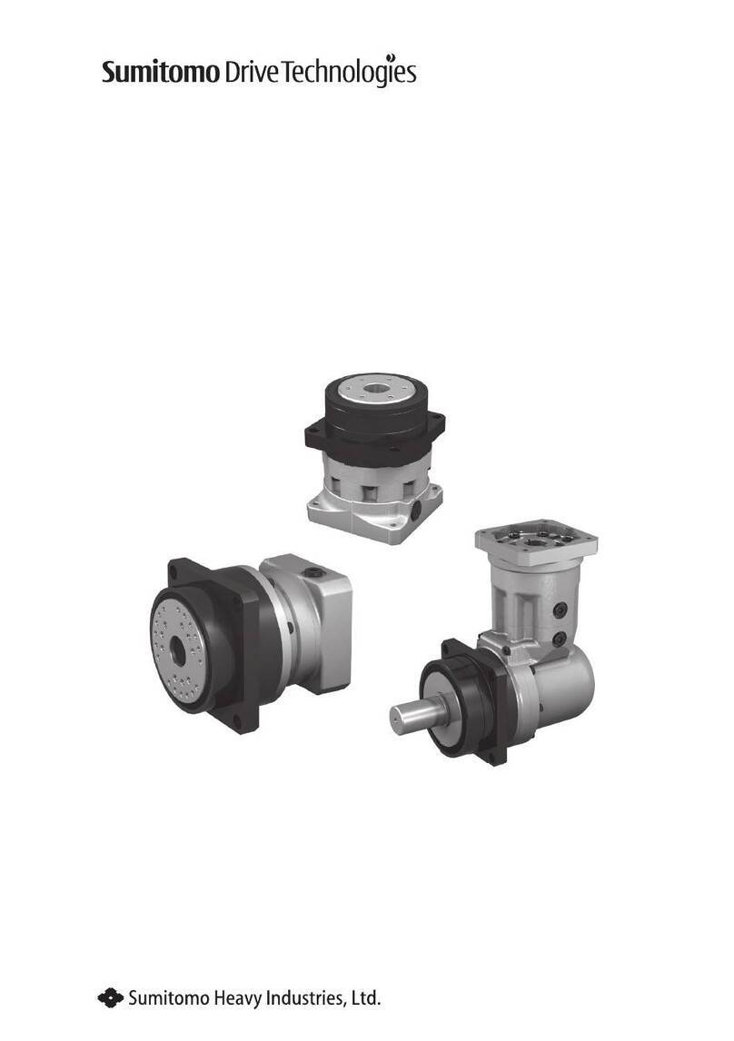
Sumitomo Drive Technologies IB Series User manual

No.ZM2003E-6Maintenance Manual
■Thisproductshouldbehandledbyonlythosewhohavebeentrainedforthework.
Pleasereadthismanualcarefullybeforeuse.
■Deliverthismanualtothecustomerwhowillactuallyusetheproduct.
■Thisinstructionmanualshouldbecarefullystored.
Planetary Gear Reducer
for Servo Motor
IB Series
P1 Type
PK1 Type
P2 Type
P Type
L Type
<Note>

1
【Introduction】
Safety Precautions

1
【Introduction】
Safety Precautions
• Carefullyreadthismaintenancemanualandallaccompanyingdocumentsbeforeuse(installation,
operation,maintenance,inspection,etc.).Thoroughlyunderstandthemachine,informationabout
safety,andallprecautionsforcorrectoperation.
Maintainthismanualforfuturereference.
• Payparticularattentiontothe"DANGER"and"CAUTION"warningsregardingsafetyandproperuse.
Improperhandlingmayresultinphysicaldamage,seriouspersonalinjury
and/ordeath.
Improperhandlingmayresultinphysicaldamageand/orpersonalinjury.
Mattersdescribedin mayleadtoseriousdangerdependingonthesituation.
Besuretoobserveimportantmattersdescribedherein.
DANGER
● Transport,installation,plumbing,wiring,operation,maintenanceandinspectionsshouldbe
handledbyproperlytrainedtechnicians;otherwise,electricshock,injury,re,ordamageto
theequipmentmayresult.
● Inthecaseofmaintenancewithdisassembly,pleasecontactourlocalsubsidiarynearestto
you.
● Whentheunitistobeusedinasystemfortransportofhumanbeings,aprotectivedevice
shouldbeinstalled.Thereisariskofpersonalinjuryordamagetotheequipmentdueto
runawayorfalling.
● Whentheunitistobeusedinanelevator,installaprotectivedeviceontheelevatorsideto
preventitfromfalling;otherwise,personalinjury,death,ordamagetotheequipmentmay
result.

2
【Contents】
3
【1】
Inspection Upon Delivery
Contents
【Introduction】
Safety Precautions ………………………………………………………………… 1
【Contents】
………………………………………………………………………………………… 2
【1】
Inspection Upon Delivery ……………………………………………………………………… 3
【2】
Storage ………………………………………………………………………………………… 5
【3】
Transportation ………………………………………………………………………………… 6
【4】
Installation ……………………………………………………………………………………… 7
【5】
Mounting the Servo Motor …………………………………………………………………… 8
【6】
Coupling with Other Machines ………………………………………………………………… 10
【7】
Operation ……………………………………………………………………………………… 12
【8】
Daily Inspection and Maintenance …………………………………………………………… 13
【9】
Troubleshooting ………………………………………………………………………………… 15
【10】
Structural Drawing …………………………………………………………………………… 16
【11】
Warranty ……………………………………………………………………………………… 21

2
【Contents】
3
【1】
Inspection Upon Delivery
CAUTION
● Unpacktheunitafterverifyingthatitispositionedrightsideup;otherwise,injurymayresult.
● Verifythattheunitreceivedisinfacttheunitordered.Whenadifferentunitisinstalled,
injuryordamagetotheequipmentmayresult.
● Donotremovethenameplate.
Upondeliveryandreceiptofthereducercheckthefollowing.Ifanonconformityorproblemisfound,
contactournearestagent,distributor,orsalesoce.
[1]Dotheitemsonthenameplateconformtowhatwasordered?
[2]Werethereanypartsthatwerebrokenduringtransport?
[3]Areallboltsandnutstightenedrmly?
1-1 How to Refer to the Nameplate
Therearetwomaintypesofnameplates:type1andtype2.Representativeexamplesareshownbelow.
Pleaseobservethembytype.
Whenmakinganinquiry,adviseusofthe[1]Nomenclatureand[2]SerialNo.
■Nameplate Type 1: P1, PK1, P2, P Type
1-2 Lubrication Method
IBSeriesisagrease-lubricatedunit.Greaseisinjectedintotheunitcomponentsbeforeshipmentsothatno
furtherlubricationisnecessaryduringuse.
[1] Nomenclature
[1]
[2]
[2] Serial No.
AP1158G
[1]
[2]
[1] Nomenclature
[2] Serial No.
[1] Nomenclature
[1]
[2]
[2] Serial No.
min
-1
kW
■Nameplate Type 2: L Type
Figure1-1Nameplate(type1)
Figure1-2Nameplate(type2)

4
【1】
Inspection Upon Delivery
5
【2】
Storage
1-3 Nomenclature
Themeaningsofthesymbolsareasfollows.Verifythatthenomenclaturematchesthatoftheorder.
A N F X F
P120
2R LD 15
MotorConnectionMethod
XFlangeonthemotor
P1,PK1,P2,PType
XM Flangeonthemotor
(withmotor)
JFlangeonthemotor
LType
JM Flangeonthemotor
(withmotor)
Backlash
L3 3min
specication P1,P2,PType
LB 6min
specication PK1Type
LC 10min
specication Ptype
LD 15min
specication P1,PK1Type
SVLB 0.5min
specication LType
SV 3min
specication
OutputShaftGeometry
N Solidshaft(keyless)
W Solidshaft(withkey)
FFlangeshaft
Note:Ltypedoesnothave
thissymbol.
MotorFlangeCode
Various
Note:Ltypedoesnothavethis
symbol.
SpecialSpecication
Blank Standard
specications
SSpecial
specication
ReductionRatio
Actualreductionratio P1,P2,P,LType
Nominalratio PK1Type
ModelSymbol
A IBSeries
OutputShaftDirection
NCanbemounted
ineitherdirection
MountingMethod
FFlange
mounting
Type/FrameSize
P1Type PK1Type P2Type PType LType
P110 PK110 P240 P10 L10
P120 PK120 P250 P15 L20
P130 PK130 P20 L30
P25 L40
P30
P35

4
【1】
Inspection Upon Delivery
5
【2】
Storage
Whenstoringreducersforanyextendedperiodoftime,considerthefollowingimportantpoints.
2-1 Storage Location
Storetheunitindoorsinacleandrylocation.
Donotstoretheunitoutdoorsorinlocationswherethereisexcessivemoisture,dust,severe
temperaturechange,corrosivegas,etc.
2-2 Storage Period
• Storageperiodshouldbelessthan1year.
• StandardRustPreventionSpecications
Externalrustprevention Standardspecificationisnocoating.The unit ispackaged with volatile
rustproofpaper,however,thesurfaceconditionshouldbecheckedforrust
onthemachinedsurfacesevery6monthsaftershipment.Whenlong-term
storageisnecessary,rustpreventionsuchasapplicationofrustprevention
oilshouldbeperformed.
Internalrustprevention Theunitshouldbestoredinsideageneralfactoryorwarehouseinan
environmentthatisfreefrommoisture,dust,severetemperaturechange,
corrosivegas,etc.
• Whentheunitwillbeshippedoverseasorstoredforaperiodoflongerthan1year,pleasecontactusfor
specialrustpreventionspecications.
• Whentheunitwillbestoredforaperiodoflongerthan1year,theunitshouldbeoperatedforafew
minutesunderno-loadconditionseverytwoorthreemonths.
2-3 Use After Storage
• The oil seal is prone todeterioration due tothesurrounding conditions such as temperature,
ultravioletrays,etc.,soafterlong-termstorage,theunitshouldbeinspectedbeforeoperation,andany
deterioratedpartsshouldbereplacedwithnewparts.
• Whenthestorageperiodis2yearsorlonger,theoilsealsandgreaseshouldbereplacedbeforestarting
operation.
• Atthestartofoperation,makesurethereisnoabnormalnoise,vibration,heat,etc.Ifanyabnormalityis
found,immediatelycontactourlocalsubsidiarynearesttoyou.

6
【3】
Transportation
7
【4】
Installation
DANGER
● Donotstanddirectlyunderaunitsuspendedbyacraneorotherliftingmechanism;
otherwise,injuryordeathmayresult.
CAUTION
● Exerciseamplecaresoasnottodroportipovertheunitduringtransportation.
● Whenliftingtheunitusingeyeboltsinthethreadedholesprovidedonthemainunit,refer
tothepackage,exteriordrawings,catalog,etc.,anddonoliftaunitthatisheavierthanthe
ratedloadoftheeyebolts;otherwise,thefalling/tumblingoftheunitordamagetothe
liftingdevicesmaycausepersonalinjuryorequipmentdamage.
● Aftertheunithasbeenmountedinthemachine,avoidliftingtheentiremachinewithusing
theeyebolts;otherwise,itmayresultininjuryordamagetotheequipmentduetotheunit
fallingortippingover,orduetofailureoftheeyebolts.
● Useproperliftingxtures,andmakesuretheeyeboltsandnutsarenotloosebeforelifting.

6
【3】
Transportation
7
【4】
Installation
CAUTION
● Donotusetheunitforapurposeotherthanthatindicatedonthenameplateorinthe
manufacturingspecications;otherwise,injuryordamagetotheequipmentmayresult.
● Donotplaceanyobjectthatwillhinderventilationaroundthereducer;otherwise,the
coolingeectisreduced,possiblyleadingtoreorburnsduetoexcessiveheatbuilt-up.
● Absolutelydonotstandonorhangfromtheunit;otherwise,injuryordamagetothe
equipmentmayresult.
● Donottouchthekeywaysoftheunitwithbarehands;otherwise,injurymayresult.
● Whentheunitisusedinfoodprocessingapplications,machinesforcleanroomandsoon,
vulnerabletooilcontamination,installanoilpanorothersuchdevicetocopewithgrease
leakageduetobreakdownorfailure;otherwise,greaseleakagemaycausefailureoftheunit,
etc.
4-1 Place of Installation
Ambienttemperature 0to40°C(Startfailuremayoccurdependingonthespeedandtorqueofthe
motorinuse,soconsultusifthereducerwillbeusedatabout0°C.)
Ambienthumidity 85%orless(P1,PK1,P2,PType),90%orless(LType).Nocondensation.
Altitude 1,000mmax.
Ambientatmosphere Thereshouldbenocorrosivegas,combustiblegas,orsteam.
Thelocationshouldbefreefromdustandwellventilated.
Installation Indoor(Freefromdust,water,otherliquids)
•Mountinginconditionsotherthantheaboverequiresadherencetospecialspecifications.Please
consultwithus.
•Mountinalocationthatenableseasyoperation,suchasinspectionandmaintenance.
•Mountonasucientlyrigidmember.
4-2 Installation Angle
Thereisnolimitonamountingangle.

8
【5】
Mounting the Servo Motor
9
【5】
Mounting the Servo Motor
5-1 P1, PK1, P2, P Type
Theproducthasaspecialshaftcouplingbetweenthereducergearandthemotorsothatanon-straight
motorshaftsuchaskey-orD-shape-cutshaftscanbeaccommodated.
Assemblethemotorinthefollowingstepsfrom(1)to(8):(Inthecaseofakey-slottedshaft,removethe
keybeforeassembly).
(1)Wiperustproongorotheroilsfromthemotorshaftsurface.
(2)Placethereduceronanappropriateworksurfacewiththecoupling[3]facingstraightup.
(3)Removetheplug[1]fromthesettinghole.
(4)Manuallyalignthecomponentssothatthecouplingtighteningbolt[2]canbetightenedfromthe
settinghole[1].
(5)Insertthemotorshaftintothecenterholeofthe coupling[3].Press theshaft straightintothe
coupling,andengagethejointbetweenthemotorandtheadapterplate[4].
P2Typewithangeplate,settheangeplate[5]betweenmotorandadapterplate[4].
Afterttingthespigotoftheangeplate[5]andadapterplate[4],insertmotorshaftintothecenter
holeofthecoupling[3],pressinverticallyandtthespigotofthemotorandtheangeplate[5].
(6)Lockthemotorandtheadapterplate[4]togetherbytighteningthemotormountingbolt.
(7)Tightenthecouplingtighteningbolt[2]fromthesettingholeusingatorquewrench.Tightentothe
appropriatetorquevalueshownonTable5-1and5-2.
(8)Reinstalltheplug[1]fromthesettinghole.
Table5-1BoltTighteningTorque(P1,PK1,PType) Table5-2BoltTighteningTorque(P2Type)
TighteningBolt Tightening
Torque
CouplingHole
Diameter TighteningBolt Tightening
Torque
CouplingHole
Diameter
M3 1.67Nm Ø6-8 M8 35Nm Ø24-35
M4 3.92Nm Ø9-14 M10 65Nm Ø35-42
M5 7.35Nm Ø16-19 M12 102Nm Ø42-55
M6 8.83Nm Ø24-28 M16 253Nm Ø60
M8 21.6Nm Ø32-38
Figure5-1Assemblydrawing
Adapte plate [4]
Plug/setting hole [1] Coupling [3]
Coupling
tightening
bolt [2]
Motor
mounting
bolt
ange plate [5]
Motor
Motor
mounting
bolt
Plug/setting
hole [1]
Plug/setting
hole [1]
Motor
Torque
wrench
Torque
wrench
Withoutangeplate Withangeplate
(SomemodelsofP2Type)

8
【5】
Mounting the Servo Motor
9
【5】
Mounting the Servo Motor
5-2 L Type
Theproducthasashaftcouplingbetweenthereducergearandthemotor.
Assemblethemotorinthefollowingstepsfrom(1)to(9).
(1)Wiperustproongorotheroilsfromthemotorshaftsurface.
(2)Placethereduceronanappropriateworksurfacewiththeoldham’scouplingfacingstraightup.
(3)Aligntheoldham’couplingboss1[5],spacer[4],andoldham’couplingboss2[2]straightandpush
insothattheclawsofthebossengagesuciently.
(4)Removetheplug[3]fromthesettinghole.
(5)Manuallyalignthecomponentssothatthecouplingtighteningbolt[1]canbetightenedfromthe
settinghole[3].
(6)Insertthemotorshaftintothecenterholeoftheoldham’couplingboss2[2].Presstheshaftstraight
intothecoupling,andengagethejointbetweenthemotorandtheadapterplate[6].
(7)Lockthemotorandtheadapterplate[6]togetherbytighteningthemotormountingbolt.
(8)Tightenthecouplingtighteningbolt[1]fromthesettingholeusingatorquewrench.Tightentothe
appropriatetorquevalueshownonTable5-3.
(9)Reinstalltheplug[3]fromthesettinghole.
Table5-3BoltTighteningTorque(LType)
TighteningBolt TighteningTorque CouplingHoleDiameter
M3 1.67Nm CCZ18
M4 3.92Nm CCZ25
M5 7.35Nm CCZ35
M8 19.6Nm CCZ50
M10 33.3Nm CCZ70
M6 8.83Nm FF10
M8 21.6Nm FF15
Figure5-2Assemblydrawing
Motor
Adapteplate[6]
Motormountingbolt
Coupling
tighteningbolt[1]
Oldham'
couplingboss2[2]
Oldham'
couplingboss1[5]
Plug/setting
hole[3]
Spacer[4]

10
【6】
Coupling with Other Machines
11
【6】
Coupling with Other Machines
CAUTION
● Conrmthedirectionofrotationbeforecouplingwiththedrivenmachine;otherwise,injury
ordamagetotheequipmentmayresult.
● Whentheproductistorunonitsownwithoutbeingconnectedtootherdevices,remove
thekeyfromtheoutputshaftinadvance.Otherwise,thekeymayyotheshaftandcause
personalinjury.
● Provideacoveretc.sothattherotatingpartcannotbetouched;otherwise,injurymayresult.
● Whencouplingthereducerwithaload,checkthatthecentering,belttension,parallelismof
thepulleys,etc.arewithinthespeciedlimits.Whentheunitisdirectlycoupledwithanother
machine,checkthatthedirectcouplingaccuracyiswithinthespeciedlimits.Whenabelt
isusedforcouplingtheunitwithanothermachine,checkthebelttension.Correctlytighten
boltsonthepulleyandcouplingbeforeoperation;otherwise,injurymayresultbecauseof
misalignment.
6-1 Checking the Rotation Direction
(1)P1,P2,P,LType
Verifythattherotationdirectionisthesameasthatoftheinputshaft.
(2)PK1Type
Verifythattherotationdirectionistheoppositeasthatoftheinputshaft.

10
【6】
Coupling with Other Machines
11
【6】
Coupling with Other Machines
6-2 Mounting a Connecting Element
•Wheninstallingaconnectingelement,becarefulnottoimpacttheshaftorapplyanexcessiveamount
ofthrustload.Bearingdamageorcollardisengagementmaybecaused.
•Installationbyshrinktorshaftendthreadengagementisrecommended.
(1)When Using a Coupling
Makesurethatthealignmenterrors(A,BandX)illustratedinFigure6.1arenotgreaterthanthe
specicationvaluesshowninTable6-1.
(2) When Using a Chain/Sprocket or Gear Coupling
•Inthecaseofchain-basedcoupling,makesurethatthetensionedchainangleisattherightangleto
theshaft.
•Refertothechaincatalogorotherappropriateinformationsourcetoknowthecorrectchaintension.
•Makesurethatthesprocketorgearpitchcirclediameterismorethanthreetimeslongerthantheshaft
diameter.
•Havethesprocketorgearloadactionpointpositionedclosertothisunitthanthecenteroftheshaft.
(RefertoFigure6-2)
(3) When Using a Timing Belt
•Excessivelytensioningthe timingbeltmaydamagetheshaftorbearing.Refertothemanufacturer’s
catalogorotherappropriateinformationsourcetoknowthecorrectbelttension.
•Refertothemanufacturer’scatalogfortheallowablevaluesofparallelismandeccentricity(β)between
pulleys.(RefertoFigure6-3)
・Havethetimingbeltloadactionpointpositionedascloseaspossibletothisunit.
Table6-1FlexibleCouplingAlignmentErrors
ASizeTolerance 0.1mmormanufacturer-
speciedvalue
BSideTolerance 0.1mmormanufacturer-
speciedvalue
DimensionX Manufacturer-specied
value
X
A
X
B
Figure6-1
Figure6-2 Figure6-3
Connectingelement
Thisproduct
Shaft
β
β

12
【7】
Operation
13
【8】
Daily Inspection and Maintenance
DANGER
● Donottouchrotatingparts(outputshaft,etc.)duringoperation;otherwise,looseclothing
caughtintheserotatingpartsmayresultinseriousinjury.
CAUTION
● Donotputngersorforeignobjectintotheopeningofthereducer;otherwise,injuryor
damagetotheequipmentmayresult.
● Thereducerwillbecomeveryhotduringoperation.Donottouchorcomeincontactwith
theunit;otherwise,burnsmayresult.
● Ifanomalyoccursduringoperation,stopoperationimmediately;otherwise,injurymay
result.
● Donotoperatetheunitinexcessoftheratedloadlevel;otherwise,injuryordamagetothe
equipmentmayresult.
7-1 Check Before Operation
Afterinstallation,checkthefollowingitemsbeforestartingoperation.
•Isthecouplingwiththedrivenmachineperformedcorrectly?
•Arethemountingboltsforeachpartsecurelytightened?
•Isthedirectionofrotationasplanned?
Aftercheckingtheitemsdescribedabove,performano-loadbreak-inoperationandgraduallyapplya
load.Whendoingthis,checktheitemsinTable7-1.
7-2 Check During Operation
Table7-1Checkitemsduringoperation
Isthereanyabnormalnoiseor
vibration?
•
Isthecasedistortedbecausetheinstallationsurfaceisnotat?
•Istherevibrationduetoinsucientrigidityofinstalledparts?
•Doesthecenteraxisofthedrivenmachinematch?
•Isvibrationofthedrivenmachinetransmittedtothereducer?
Isthesurfacetemperatureabnormally
high? •Istheambienttemperatureattheplaceofusagehigh?
Whenanabnormalityisfound,stopoperationandcontactourlocalsubsidiarynearesttoyou.
12
【7】
Operation
13
【8】
Daily Inspection and Maintenance
DANGER
●Donotcomeclosetoortouchanyrotatingparts(outputshaft,etc.)duringmaintenanceor
inspectionoftheunit;otherwise,looseclothingcaughtintheserotatingpartsmayresultin
injuryordeath.
CAUTION
● Donotputngersorforeignobjectintotheopeningofthereducer;otherwise,injuryor
damagetotheequipmentmayresult.
● Thereducerwillbecomeveryhotduringoperation.Donottouchtheunitwithbarehands;
otherwise,burnsmayresult.
● Identifyandprovideappropriatecorrectiveactioninatimelyfashionandaccordingtothis
maintenancemanualifanyabnormaloperatingcharacteristicsareobserved.Donotoperate
theunitcorrectiveactionhasbeentaken.
● Donotusedamagedreducers;otherwise,injuryordamagetotheequipmentmayresult.
● Wecannotassumeanyresponsibilityfordamageorinjuryasaresultofanunauthorized
modicationbyacustomer.
● Disposeofthereducerasgeneralindustrialwaste.

14
【8】
Daily Inspection and Maintenance
15
【9】
Troubleshooting
8-1 Daily Inspection
Toensureproperandcontinuedoptimumoperation,usetable1toperformdailyinspections.Allofthe
answersshouldbe"No."
Table8-1DailyInspection
InspectionItem DetailsofInspection
Noise Isthereabnormalsound?Istheresuddenchangeinsound?
Vibration Isvibrationabnormallylarge?Doesvibrationchangesuddenly?
Surfacetemperature Isthesurfacetemperatureabnormallyhigh?Doesthesurface
temperaturerisesuddenly?
Greaseleakage Isthereanygreaseleakagefromthegears?Isthereanyrustonthe
slidingsurfaceoftheoilseal?
Installationbolts Haveanyoftheinstallationboltsbecomeloose?
ChainTimingbelt Isthechainortimingbeltloose?
•Ifanyabnormalconditionisobservedduringthedailyinspection,remedythesituationbyreferringto9,
“Troubleshooting”(page15.Iftheabnormalconditionstillpersists,contactourlocalsubsidiarynearest
toyou.
8-2 Maintenance of Main Unit
•Oilseals havea life,andafterlong-termusetheremaybeadecreaseinthe sealeectduetonatural
deteriorationandwear.Althoughtheseallifegreatlydiersdependingontheoperatingconditionsand
surroundingenvironmentofthereducer,itisrecommendedthatthesealbereplacedevery1to3years.
Iftheslidingsurfaceoftheoilsealbecomeswornorrusted,replacethesealwithanewone.
Theslidingsurfaceismadeofacarbonsteel,sorustingmayoccurandadvanceduetomoisture,etc.,
whichmayleadtodamageoftheoilseal,soperiodicallytakerustpreventionmeasures.
8-3 Backlash
Theproducthasbeenassembledwithapreconditionedbacklash.
Acompletebacklashreconditioningwouldbenecessaryiftheproductisdisassembled.Donot
disassembletheproduct.

14
【8】
Daily Inspection and Maintenance
15
【9】
Troubleshooting
Ifanyabnormalconditionisobservedinorrelatedtothisunit,promptlyremedythesituationby
referringtoTable9-1.Iftheabnormalconditionstillpersists,contactourlocalsubsidiarynearesttoyou.
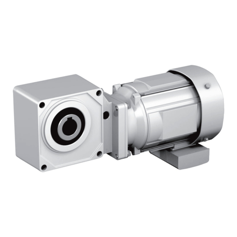
Table9-1Troubleshooting
Condition Possiblecauses Control
Themotorrunswhenwithoutload,
buttheoutputshaftdoesnotturn
Unitdamagedduetogear
overloadingetc. Contactourlocalsubsidiary
Themotorrunswiththeoutput
shaftturningwhenwithoutload
butwhenloadisapplied
Cannotrunfastand
becomesoverheated Unitoverloaded Reducetheloadtothe
specicationlevel
Stops
Thekeyisnottted Fitthekey
Bearingisburned Contactourlocalsubsidiary
Runsinthereversedirection Controlsetuperror Changethecontrolsetup
Tueunitbecomesexcessively
heated
Unitoverloaded Reducetheloadtothe
specicationlevel
Ambienttemperatureattheuse
locationistoohigh Improveventilation
Bearingdamaged Contactourlocalsubsidiary
Reductiongearsexcessivelyworn
duetooverloadingetc. Contactourlocalsubsidiary
Greaseleaking
Small amounts of grease
seepingoutordroolingfrom
inputoroutputshaftseals
Greaseappliedtotheoilseals
tendstoseepoutfromthesealsat
thebeginningofuse
Wipethegreaseotheoilseals
andobservethecondition
Inputoroutputshaftarea
Greaseleakage Oilsealorshaftdamaged Contactourlocalsubsidiary
Greaseleakingfromcase
jointsorothermatingfaces Tighteningboltloose Contactourlocalsubsidiary
Abnormalnoise
Abnormallyseverevibration
Debrisorforeignobjectsinsidethe
bearing,orthebearingisdamaged Contactourlocalsubsidiary
Foreignobjectsstuckbetween
reductiongears Contactourlocalsubsidiary
Reductiongearsdamaged Contactourlocalsubsidiary
Casedeformedduetothe
installationsurfacenotbeing
completelyat
Correcttheinstallationsurface
tomakeitcompletelyatoruse
linersetc.foradjustment
Resonanceduetotheinstallation
surfacenotbeingsucientlyrigid
Reinforcetheinstallationsurface
forgreaterrigidity
Shaftmisalignmentwiththe
drivenmachine Aligntheshafts
Vibrationofthedrivenmachine
transmittedtothereducer
Runthereduceronitsownto
locatethenoisesource

16
【10】
Structural Drawing
17
【10】
Structural Drawing
10-1 Structural Drawing (P1 Type)
1 2 3 4 5 6 7 8 9 10 11 12 13 14 15
PartNumber Description
1Outputshaft
2Oilseal
3Bearingofoutput
4 Sungearofoutput
5Planetarygearofoutput
6Casingwithinternalgear
7 Sungearofinput
8 Planetarygearofinput
9 Internalgearofinput
10 Jointcover
11 Oilseal
12 Inputshaftbearing
13 Coupling
14 Adaptorplate
15 Motor(Providedbytheuser)
Table10-1MainComponents(P1Type)
Figure10-1P1TypeDouble-reduction(example:ANFX-P120N)

16
【10】
Structural Drawing
17
【10】
Structural Drawing
10-2 Structural Drawing (PK1 Type)
1 2 3 5 64 9
10
8
12 1411 13
7
15
16
17
18
19
20
21
22
24
25
23
PartNumber Description PartNumber Description
1Outputshaft 14 Casing
2Oilseal 15 Bearing
3Bearingofoutput 16 IntermediateShaft
4 Sungearofoutput 17 Spiralbevelgear
5Planetarygearofoutput 18 Pinionshaft
6Casingwithinternalgear 19 Bearing
7 Sungearofinput 20 Cover(Casing)
8 Planetarygearofinput 21 Oilseal
9 Internalgearofinput 22 Inputshaftbearing
10 Adaptor(Casing) 23 Coupling
11 Oilseal 24 Adaptorplate
12 O-ring 25 Motor(Providedbytheuser)
13 Bearing
Table10-2MainComponents(PK1Type)
Figure10-2PK1TypeTriple-reduction(example:ANFX-PK120N)

18
【10】
Structural Drawing
19
【10】
Structural Drawing
10-3 Structural Drawing (P2 Type)
1 2 3 4 5 6 7 8 9 10 11 12 13 14 15
Figure10-3P2TypeDouble-reduction(example:ANFX-P250F)
PartNumber Description
1Outputshaft
2Oilseal
3Mainbearing
4 Sungearofoutput
5Planetarygearofoutput
6Casingwithinternalgear
7 Sungearofinput
8 Planetarygearofinput
9 Internalgearofinput
10 Jointcover
11 Oilseal
12 Inputshaftbearing
13 Coupling
14 Adaptorplate
15 Motor(Providedbytheuser)
Table10-3MainComponents(P2Type)
Other manuals for IB Series
2
Table of contents
Other Sumitomo Drive Technologies Engine manuals

Sumitomo Drive Technologies
Sumitomo Drive Technologies HYPONIC DRIVE User manual

Sumitomo Drive Technologies
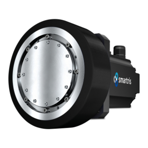
Sumitomo Drive Technologies Smartris User manual

Sumitomo Drive Technologies
Sumitomo Drive Technologies RHYTAX User manual

Sumitomo Drive Technologies
Sumitomo Drive Technologies IB Series User manual
Popular Engine manuals by other brands

Ametek
Ametek dunkermotoren D258 operating manual

MINSK
MINSK D-260.1S3? Operation & maintenance manual

Coleman
Coleman F15BM owner's manual

MOTO GUZZI
MOTO GUZZI V85 E4 manual

Briggs & Stratton
Briggs & Stratton Vanguard 540000 Series Operating & maintenance instructions

Vimar
Vimar ELVOX EV45ER/10 Installation and operation manual